1
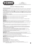
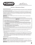
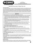
ZINKO
MODELS
ZPK-20
Portable Power Sets
Hydraulic Jack
Toll Free: 1-800-579-8088 Web: www.zinko.com
Operating Instructions & Repair Parts List
Safety Precautions
Failure to read the following precautions may result in loss of load, damage or failure of equipment,
! CAUTION resulting in property damage and/or personal injury.
! WARNING
All Warning Statements must be carefully observed to help prevent personal injury.
1. The owner of this set is responsible for it being installed and operated according to federal (OSHA), state, and
local safety standards.
2. Read, understand, and follow all safety precautions and instructions included with the set. Safety-related decals
must be installed, maintained, and replaced if they become hard to read.
3. Wear eye protection that meets ANSI Z87.1 and OSHA standards.
4. This is designed for vehicle body/frame applications. Using this equipment in an application for which it is not
designed could result in overloading, reduced load capacity, reduced stability, and/or system failure.
5. DO NOT OVERLOAD THE HYDRAULIC SYSTEM. Creating pressure beyond the rated capacity of the pump and
ram may result in personal injury. Overloading is indicated by bowing extension tubes or slipping attachments.
6. Attachments and extension tubes must be aligned and fully engaged so ram force is straight, avoiding an offcenter load condition.
Hydraulic Hose Safety
1. Before operating the pump, tighten all hose connections using the correct tools. DO NOT OVER TIGHTEN.
Connections need only be secure and leak-free. Over tightening can cause premature thread failure or high
pressure fittings to split at pressures lower than their rated capacities.
2. Should a hydraulic hose ever rupture, burst, or need to be disconnected, immediately shut the pump off and
open the control valve to release all pressure. NEVER GRASP A LEAKING PRESSURIZED HOSE WITH YOUR
HANDS. The force of escaping hydraulic fluid could cause serious injury.
3. DO NOT subject the hose to any potential hazard such as fire, extreme cold or heat, sharp surfaces, or heavy
impact. DO NOT allow the hose to kink, twist, curl, or bend so tightly that the fluid flow within the hose is
blocked or reduced. DO NOT use the hose to move attached equipment. Periodically inspect the hose for wear
because any of these conditions can damage the hose and result in personal injury.
4. Hose material and coupler seals must be compatible with the hydraulic fluid used. Hoses also must not come in
contact with corrosive materials such as creosote-impregnated objects and some paints. Consult the manufacturer before painting a hose. NEVER PAINT COUPLERS. Hose deterioration due to corrosive material can result
in personal injury.
5. Some components in this set do not match the maximum pressure rating of the pump and ram. USE A
PRESSURE GAUGE IN THE SYSTEM TO MONITOR HYDRAULIC PRESSURE. Refer to the instructions in this
document for Typical Applications and Load Capacities.
Pump Safety
1. DO NOT EXCEED THE MAXIMUM CAPACITY OF THE PUMP OR TAMPER WITH THE INTERNAL HIGH
PRESSURE RELIEF VALVE. Creating pressure beyond the rated capacity can result in personal injury.
2. Completely retract the ram before opening the filler screw on the pump to add hydraulic fluid. An overfill can
cause personal injury due to excess reservoir pressure created when rams are retracted.
Ram Safety
1. DO NOT EXCEED THE MAXIMUM CAPACITY OF THE RAM. Creating pressure beyond the rated capacity can
result in personal injury.
2. DO NOT SET POORLY-BALANCED OR OFF-CENTER LOADS ON THE RAM. The load may tip and cause personal
injury.
Operating Instructions
Setup
The pump may be operated in a horizontal position or in a vertical position with the head pointing down as shown.
1. Assemble the hose between the pump and ram.
2. Determine the appropriate attachment for your application; assemble the attachment to the ram piston.
Bleeding Air From the System
Air can accumulate in the hydraulic system during the initial setup or after prolonged use causing the ram to respond
slowly or in an unstable manner. To remove the air:
1
Zinko Hydraulic Jack
Models: ZPK-20 Operating Instructions (continued)
1. Place the ram at a lower level than the pump with the piston end pointing down.
2. Extend and retract the ram several times without putting a load on the system. Air will be released into the pump
reservoir.
3. With the ram fully retracted, the pump sitting level, and no pressure in the hydraulic system, remove the pump's filler
screw. Fill the reservoir with approved hydraulic fluid until the fluid level is within 1/2" from the top of the reservoir.
BENCH
FLOOR
IMPORTANT: The use of extension tubes or off-center attachments greatly reduces the capacity of the hydraulic system.
When using extension tubes, put the shortest tubes on the end.
Some components in this set do not match the maximum pressure rating of the pump and ram. USE A PRESSURE
GAUGE IN THE SYSTEM TO MONITOR HYDRAULIC PRESSURE.
Operation
1. Turn the pump's release valve clockwise to a closed position. IMPORTANT: HAND TIGHTEN THE VALVE ONLY.
2. Work the pump handle up and down to send oil through the hose to the ram, causing the piston to extend to the
work piece.
3. Monitor the pressure gauge while completing the application.
NOTE: The pump is equipped with an overload valve that will bypass oil back into the pump reservoir in an overload
situation (when the system meets maximum pressure). In this case, continued pumping will have no effect on the
system. If an overload system commonly occurs, a higher capacity set is needed.
4. To release pressure, slowly turn the release valve counterclockwise (the release speed is controlled by how fast the
valve is opened).
2
Zinko Hydraulic Jack
Models: ZPK-20
To prevent personal injury, release pump pressure and disconnect the hose from the pump before
making repairs. Repairs must be performed in a dirt-free environment by qualified personnel who are
familiar with this equipment. If the following solutions do not remedy the problem, take the product to an authorized
service center for repair.
! CAUTION
Troubleshooting
PROBLEM
Pump Looses Pressure
1.
1.
Pump Not Delivering Fluid
2.
1.
Pump Does Not Reach Rated 2.
Capacity
3.
CAUSE
System components leaking.
Fluid level is low.
Seats are worn.
Low fluid level in reservoir.
System components leaking.
Fluid leaking past inlet or outlet checks.
Pump Handle has a "Spongy" 1. Air trapped in system.
Feel
2. Too much fluid in reservoir.
1. Check the air supply.
Pump will Not Build To
Maximum Pressure
2. Pressure regulator improperly adjusted
(no visable leakage)
(if so equipped).
1. Loose couplers.
2. Low fluid level in pump reservoir.
Ram Piston Will Not Extend
3. Ram seals leaking.
Ram Piston Extends
Only Partially
1.
2.
1.
2.
Ram Piston Extends Slower
3.
Than Normal
4.
Ram Does Not Hold Pressure
Low fluid level in reservoir.
Load is above capacity of system.
Loose couplers.
Restricted hydraulic line or fitting.
Pump not working correctly.
Ram seals leaking.
1.
1.
2.
1.
2.
3.
1.
2.
1.
2.
1.
2.
3.
1.
2.
1.
2.
3.
4.
1. Leaky connection.
1.
2. Ram seals leaking.
2.
3. Pump or valve not working correctly.
1. Worn or damaged seals.
3.
1.
2. Loose connection.
2.
Ram Leaks Hydraulic Fluid
1.
2.
Ram Will Not Retract or
3.
Retracts Slower Than Normal 4.
5.
6.
Pump release valve close.
Loose couplers.
Blocked hydraulic lines.
Weak or broken retraction springs.
Ram damaged internally.
Pump reservoir too full.
1.
2.
3.
4.
5.
6.
SOLUTION
Repair or replace as necessary.
Check fluid level.
Repair seats or replace pump body.
Check fluid level.
Repair or replace as necessary.
Repair inlet or outlet checks, or replace
high pressure piston seal.
Refer to Bleeding Air From the System .
Check fluid level.
100 psi (7 BAR) is required to obtain
maximum pressure.
Adjust according to instructions on
Operation section.
Tighten couplers.
Fill and bleed the system.
Replace worn seals. Look for excessive
contamination or wear.
Fill and bleed system.
Use correct equipment.
Tighten couplers.
Clean and replace if damaged.
Repair or replace as necessary.
Replace worn seals. Look for excessive
contamination or wear.
Clean, reseal with thread sealant, and
tighten connection.
Replace work seals. Look for excessive
contamination or wear. Replace
contaminated fluid.
Repair or replace as necessary.
Replace work seals. Look for excessive
contamination or wear. Replace
contaminated fluid.
Clean, reseal with thread sealant, and
tighten connection.
Open pump release valve.
Tighten couplers.
Clean and flush lines.
Send to service center for repair.
Send to service center for repair.
Drain fluid to correct level.
3
Zinko Hydraulic Jack
Model: ZPK-20 Parts Breakdown
Model ZPK-20
Part No.
92120 - 01
92120 - 02
92120 - 03
92120 - 05
92120 - 06
92120 - 07
92120 - 08
92120 - 09
92120 - 10
92120 - 11
92120 - 12
92120 - 13
92120 - 14
92120 - 15
92120 - 16
92120 - 17
REV 071007
20-Ton Set
Description
Hydraulic Pump
Hose
Ram
Extension Tube, 27.5"
Extension Tube, 20"
Extension Tube, 10"
Extension Tube, 5"
Male connector
Serrated Saddle
Plunger Base
V-Head
Wedge Head
Toe Lift
Threaded Coupling
Lock Pin
Metal Carrying Case
ZINKO HYDRAULIC JACK
4
PO Box 4903, Ontario, CA 91761
Toll Free: 1-800-579-8088
http://www.zinko.com
Phone: (909) 989-9526
Fax: (909) 989-1724