1
United States Patent [19]
v[11]
[45]
Hertzer et al.
[54] ENERGY-CONSERVING INJECTION
MOLDING MACHINE
World, Feb. 1986, p. 15.
A. Chorey; Harold J. Faig, both of
Cincinnati, all of Ohio
Cincinnati Milacron Inc., Cincinnati,
Ohio
[21] Appl. No.: 616,752
[22] Filed:
Oct. 1, 1991
Article: “IMM Power Use Cut by 70%”, Plastics
’
[75] Inventors: Ronald A. Hertzer, Milford; Edward
[73] Assignee:
5,052,909
Patent Number:
Date of Patent:
Nov.16,1990
‘
Paper: “A Universal Controller for Parallel Pumps with
Variable Frequency Drives”, P. W. Hammond, The
Volume of Conference Proceedings of I.E.E.E. Indus
try Application Society, 17th Annual Meeting, San
Francisco, Calif, Oct. 4-7, 1982.
Article: “Using Industrial Hydraulics", T. C. Franken
field, Second Ed. 1984, pp. 6-32, 6-40 through 6-46,
10-16 through 10-20.
Unpublished Cincinnati Milacron, Inc., documents de
scribing VISTA Hydraulic Clamp Machines, 12 sheets.
“Installation and Operation Instruction Manual”, Wer
[63]
Related U.S. Application Data
Continuation of Ser. No.‘ 467,634, Jan. 19, 1990, aban
doned.
[51]
[52]
Systems for the Industrial World", Wertec Corpora
Int. Cl.5 ..................... .. B29C 45/80; B29C 45/82
U.S. Cl. ............................... .. 425/150; 425/450.l;
425/589; 425/451.9
[58]
Field of Search ................... .. 425/135, 150, 450.1,
425/450.9, 589
[56]
References Cited
U.S. PATENT DOCUMENTS
3,509,600
tec Corporation, Model 2000 and 3000 Brushless Motor
Controller.
Brochure: “The Most Unique Line of Brushless Drive
5/1970
Noble ................................ .. 425/145
3,822,057 7/1974 Wheeler
425/145
4,146,601
425/145
3/1979
Bishop .... ..
tron.
Primary Examiner-Willard Hoag
Attorney, Agent, or Firm—Wood, Herron & Evans
[5 7]
ABSTRACT
A hydraulic injection molding machine incorporates a
pump driven by a variable speed motor preferably of
the brushless DC type. The machine controller outputs
driving signals to adjust the speed of the motor so that
the flow delivered by the pump substantially matches
the hydraulic demand imposed during each phase of the
machine operating cycle. The pump is preferably a
4,589,830 5/1986 Clawson
425/150
4,712,991 12/1987
425/145
variable displacement type and is connected to a fast
4/1988 Sasaki et al.
.. 425/145
2/1990 Jones et al. .....................
318/560
responding pump control for selectively carrying out
pressure compensation or flow compensation. The val
4,735,564
4,904,913
Hehl ........... ..
OTHER PUBLICATIONS
Article: “Closed-Loop Servohydraulics: Born to Auto
mation”, Ronald A. Hertzer and Michael W. Green:
Plastics Machinery & Equipment, Nov. 1988, pp. 38-39. .
Brochure: “VISTA Injection Molding Machines VH
Series”, Cincinnati Milacron, Inc., May 1988.
VISTA HYDRAULIC USER’S MANUAL, Cincin
nati Milaron, Inc., Publication PM-421-l, Oct. 1988.
"1917'
I NJECTION
CONTROL
MACH":
COGTRMLEI
ues of the motor driving signals are calculated so that
the motor/pump combination is operated at or near
maximum efficiency except when the pump control
varies the displacement of the pump to effect pressure
or ?ow compensation. Hydraulic transient response is
further improved by connecting the output of the pump
to an accumulator by way of a check valve.
10 Claims, 3 Drawing Sheets
U.S. Patent
Oct. 1, 1991
Sheet 2 of 3
5,052,909
cm N EQT
TO 57
_‘
TO cuscx
l
VALVE 49
II
I
I
l
‘a;
I
I
I
I
I
l
I
I
l
I
I
Jl
I
I
t-Y-n- 4-! -J
I
I
I
l
l
L_________‘________
1...- ....__.._________.._.__
RESERVOIR
230
FIG. 3
I354
FIG.2
U.S. Patent
Oct. 1, 1991
Sheet 3 of 3
R E AD MOLDI N G
PARAMETERS
l
CALCULATE
FLOW RATES
1
CALCULATE
OPERATING SIGNAL
VALUES
CALCULATE
omvms SIGNAL
VALUES
l
CALCULATE
FLOW/PRESSURE
COMPENSATION
SIGNAL VALUES
I
LOAD VALUES
INTO SEQUENCE
PROGRAM
FIG.4
5,052,909
1
5,052,909
2
difference between the actual ?ow delivered by the
ENERGY-CONSERVING INJECTION MOLDING
pump and the instantaneous demand, is pumped over
MACHINE
relief valves. ‘In doing so, energy is wasted. Some of the
wasted energy is given off in the form of heat which
This is a continuation of copending application Ser. 5 i causes undesirable heating of the hydraulic ?uid itself.
No. 07/467,634 ?led on Jan. 19, 1990, now abandoned.
Further energy must be expended when the ?uid tem
perature rises to a point where active cooling is required
FIELD OF THE INVENTION
to restore the ?uid to a suitable operating temperature.
In an effort to overcome these problems, there have
been various attempts in the prior art to match the out
put of the hydraulic pump with the demand presented »
by the rest of an injection molding machine.
One such attempted solution has been to provide a
The invention relates to hydraulic injection molding
machines offering improved energy ef?ciency. More
particularly, the present invention relates to hydraulic
injection molding machines incorporating a means for
adjusting the output of the hydraulic pump in accor
dance with the different hydraulic demands imposed by
hydraulic injection molding machine having a ?xed
the machine during different phases of its operating 15 displacement hydraulic pump driven by an AC motor
cycle so that the output of the pump does not signi?
cantly exceed the imposed demand in order to conserve
energy.
with an adjustable speed drive such as a variable fre
quency or inverter type drive. By varying the speed
control input to the drive, the motor speed and there
fore the pump delivery rate can be varied to more
BACKGROUND OF THE INVENTION
20 closely approximate the actual hydraulic demand. Un
Injection molding is a process for converting material
fortunately, the energy savings of such machines are
from one form or shape to another by expending en
ergy. Typically, material in the raw form of solid pellets
is loaded into an injection molding machine wherein the
realized at the expense of machine performance. Be
cause the moving components of the motor/pump as
sembly cannot be accelerated or decelerated very rap
pellets are ?rst converted to a molten state by introduc 25
idly, the frequency response of the machine is degraded.
As a result, molded part quality may be adversely af
ing energy in the form of heat and mechanical shear.
Further energy is expended to inject the plasticized
material under pressure into a mold having a cavity
de?ning the ?nal shape of the part to be produced while
the mold is clamped forcibly closed. Additional energy
fected due to variations in molding parameters such as
shot weight, injection velocity and injection pressure.
The assignee of the present application has marketed
30
is used to cool the material within the mold to return it
a line of hydraulic clamp machines under the trademark
calling for slower injection. Also, phases of the machine
operating cycle such as the clamp open phase typically
require greater hydraulic ?ows than the part curing
phase. While a hydraulic injection molding machine
must be capable of supplying whatever maximum ?uid
loop control of injection velocity, injection pressure,
to a solid state. The mold clamp is then opened, the - VISTA. Those machines utilize a ?xed RPM AC motor
to drive an axial piston, swash-plate design, variable
molded part ejected and the mold reclosed in prepara
displacement pump to insure that only the amount of
tion for molding the next part. The laws of physics
require that the total energy input to the molding ma 35 ?ow necessary to meet load conditions is delivered by
the pump thereby reducing energy usage and hydraulic
chine equally balance the energy output.
?uid heating. A hydraulic feedback circuit is used to
In an hydraulic injection molding machine, energy is
effect either pressure compensation or ?ow compensa
input to the machine in the form of electrical energy.
tion of the pump output on a selectable basis by moving
Much of this energy is converted into hydraulic ?ow
the angle of the swash-plate of the pump to vary its
energy by means of an electric motor drivably con
stroke. Since such control action does not require accel
nected to a hydraulic pump. The fluid delivered by the
eration or deceleration of high inertia rotating compo
pump serves to operate various hydraulic components
nents of the motor/pump assembly, response time is
including electro-hydraulic control valves and hydrau
signi?cantly improved as compared to the ?xed dis
lic actuators. The pressure or volume ?ow demands for
hydraulic fluid vary considerably not only from one 45 placement pump/variable speed AC motor machines
discussed above. Further improvements in transient
given machine set-up to another but, also during differ
response are realized by connecting the pump output to
ent phases of the operating cycle of a machine in any
a gas-charged accumulator. The output of the accumu
given set-up. For instance, a set-up requiring rapid in
lator is connected to a multi-function servo-controlled
jection of the material into the mold will require a
higher volume flow rate than that needed for a set-up 50 proportional directional valve which provides closed
back pressure and melt decompression. Nevertheless,
the energy savings realized in VISTA model machines
has been less than the savings made possible by the
55 present invention.
pressure and/or ?ow requirements are needed to meet
SUMMARY OF THE INVENTION
the machine’s maximum rated capacity, signi?cant en
In view of the foregoing drawbacks of the prior art,
ergy losses have been incurred when operating under '
conditions where lesser hydraulic ?uid pressures and
it is an object of the present invention to provide an '
/or volume ?ow rates are required to operate the ma
energy-conserving injection molding machine which
chine than the pressure and/or volume ?ow actually
delivered by the pump.
In machines having a ?xed-displacement hydraulic
?uid pump driven by a ?xed-speed electric motor, the
pump must be driven to constantly deliver suf?cient 65
affords greater energy savings than prior art machines
while maintaining excellent response characteristics.
?ow capable of satisfying maximum machine require
ments even though the instantaneous hydraulic demand
may be signi?cantly lower. The excess flow, i.e., the
In accordance with a ?rst aspect of the present inven
tion, an energy-conserving injection molding machine
which includes a hydraulic pump driven by a brushless
_ DC motor is provided. Such a motor affords a consider
able advantage in energy ef?ciency as compared to the
variable speed AC pump motors of the prior art.
3
5,052,909
In accordance with a second aspect of the invention,
a variable speed motor, preferably of the brushless DC
type, is used to drive a variable displacement hydraulic
pump. The electronic machine controller delivers a
driving signal to the motor drive to adjust the motor
speed in accordance with desired molding parameters.
with certain aspects of the invention, may also suitably
The motor speed is selected to substantially match the
output of the pump to the hydraulic load expected dur
ing a particular phase of the machine operating cycle
given the molding parameters entered into the control
ler by an operator. The controller automatically outputs
new driving signals as the machine cycles through pha
ses of operation characterized by different hydraulic
loads. The displacement of the pump is governed by a
pump control which selectively regulates the flow de
livered by the pump in either a pressure compensation
4
27 and 28. Pump 26 communicates with a reservoir 30
by way of a case drain line 31 and a supply line 32 and
is driven by an electric motor 34 which receives electri
cal input energy at 35. Preferably, motor 34 comprises a
variable speed brushless DC motor but, in accordance
comprise other variable speed motors either AC or DC.
Motor 34 is mechanically connected to pump 26 by way
of a rotatable shaft 33. In order to conserve energy by
matching the hydraulic output of pump 26 to the de
mand during different phases of the operating cycle of
machine 10, the invention contemplates controlling the
speed of motor 34 and shaft 33, and thus the output of
pump 26, with a driving signal 40 generated by machine
15 controller 15 in a manner to be described in further
detail hereinafter. For present purposes it is sufficient to
note that machine controller 15 calculates the magni
or flow compensation mode. The pump control is capa
ble of responding to load changes quickly and therefore
provides improved transient response. To further im
tude of driving signal 40 for each phase of the operating
cycle of machine 10 from the particular molding param
prove transient response, the pump output is connected
to a gas-charged accumulator by way of a check valve.
eters entered by an operator through operator interface
16 during the setup of machine 10. The molding param
These and other aspects and advantages of the present
eters determine the hydraulic demand expected during
invention will be apparent to persons of ordinary skill in
each
phase of the machine cycle.
the art in view of the following detailed description
taken in conjunction with the drawings wherein like 25 The hydraulic flow delivered by pump 26 is moni
tored, via a line 42, by a pump control 43. Pump control
reference numerals designate like items.
43, which will be described in further detail with refer
BRIEF DESCRIPTION OF THE DRAWINGS
ence to FIG. 3, communicates with pump 26 via a line
44 to operate pump 26 to operate in either a pressure
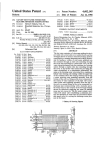
FIG. 1 is a schematic diagram of an injection molding
compensation mode or a flow compensation mode in
machine constructed in accordance with the present
accordance with an electrical pressure or flow compen
invention.
sation signal delivered to pump control 43 from ma
FIG. 2 is a cross-sectional view of a variable-displace
chine controller 15 by way of a signal path 46. In order
ment pump preferred for use as the pump shown in
to improve hydraulic transient response, the output of
FIG. 1.
pump
26 which supplies manifolds 27 and 28 is prefera
FIG. 3 is a schematic diagram illustrating the pump 35
bly connected to a gas-charged accumulator 48 through
control of FIG. 1 in further detail.
a check valve 49.
FIG. 4 is a flow diagram illustrating the manner in
Accumulator 48 has a ballast charged at an initial
which the controller of FIG. 1 derives a motor driving
signal.
internal pressure that resists the ?ow of liquid into its
interior. The design of such accumulators is well known
DETAILED DESCRIPTION OF THE
PREFERRED EMBODIMENT
FIG. 1 illustrates a preferred embodiment of an injec
tion molding machine 10 constructed in accordance
with the present invention. Machine 10 includes an 45
injection unit 11 juxtaposed a clamping unit 12. The
sequence, timing and quantitative values associated
with the various operations performed by injection unit
11 and clamping unit 12 are carried out under the direc
tion of an electronic machine controller 15 in accor
within the art. When the pressure in the line to which
accumulator 48 is attached exceeds the internal pressure
of the accumulator, hydraulic ?uid will flow into accu
mulator 48 compressing the ballast. When the line pres
sure drops below the internal pressure of the accumula
tor, hydraulic fluid will ?ow from accumulator 48 into
the line. Thus, if pump 26 and motor 34 lag behind the
demand for flow rate created by valves opening in one
of the control circuits 20 or 21, accumulator 48 rapidly
50 responds to temporarily make up the additional de
dance with molding parameters entered into controller
15 by an operator through an operator interface 16.
Closed-loop control is facilitated by a plurality of feed
back signals 18 which controller 15 receives from injec
tion unit 11 and clamping unit 12. Injection control 20 55
and clamp control 21 serve as electro-hydraulic inter
faces between machine controller 15 and injection unit
11 and clamping unit 12, respectively. Injection control
20 and clamp control 21 are well known in the art and
comprise electrically controlled proportioning valves
and other hydraulic and electro-hydraulic devices ar
ranged for generating the hydraulic pressures and/or
?ows necessary for operating injection and clamping
unit 12 in accordance with various operating signals
received from machine controller by way of respective
multiple signal paths 23 and 24, respectively.
Hydraulic fluid is supplied to injection control 20 and
clamp control 21 from a pu ..p 26 by way of manifolds
mand. Thus, accumulator 48 provides more precise and
faster-responding matching of flow delivery with flow
demand.
Injection unit 11 includes an injection screw 52 that is
rotatably coupled to a hydraulic extruder motor 53 by
way of a shaft 54. The rotational direction and speed of
motor 53 and thus, those of ‘screw 52 are governed by
the hydraulic flow directed to motor 53 from injection
control 20 by way of a pair of hydraulic lines 57 and 58.
In order to sense the hydraulic ?ow to extruder motor
53 during the “extruder run” phase of the machine
operating cycle, line 58, which emanates from the out
put side of an electrically controlled throttle (not
shown) located within injection control 20, is connected
65 to pump control 43 by way of a line 56. The purpose of
the latter connection will be made clear in connection
with the description of pump control 43 with reference
to FIG. 3 hereinafter.
5
5,052,909‘
Injection screw 52 is housed within a barrel 60 having
a nozzle end 61. Barrel 60 communicates with a hopper
(not shown) which may be ?lled with a moldable mate
_ ceives piston 110 in hydraulically sealed relation. Inte
rior volume 112 is selectively ?uidly connected to ‘or
sealedfrom a pre?ll reservoir 116 by means of a valve
rial usually in the form of solid pellets or granules. As
117. Valve 117 is actuated by clamp control 21 by way
screw 52 rotates in one direction within barrel 60, the
barrel is ?lled with the material which is transformed
of a pair of lines 119 and 120. Valve 117 includes a
movable valve stem 122 which is sealably engageable
with a seat 123 formed in the wall of cylinder 113. After
into a molten plastic state by the mechanical shearing
action of screw 52. Plasticizing of the molding material
may be assisted by one or more electric heaters (not
shown) mounted in thermal contact with barrel 60. As
moldable material accumulates within barrel 60 from its
nozzle end 61 rearwardly (to the left in FIG. 1), screw
52 is forced axially rearwardly within barrel 60.
Screw 52 may be selectively extended or retracted
within barrel 60 at a desired rate by means of a pair of
volume 112 has been ?lled by opening valve 117, valve
117 is closed to seal valve stem 122 against seat 123. In
order to hold mold 89 clamped forcibly closed, interior
volume 112 is hydraulically charged under high pres
sure by clamp control 21 through a hydraulic line 125
coupled to an inlet port 126 formed in the wall of cylin
der 113. The hydraulic pressure within volume 112 is
monitored at line 125 by a pressure transducer 128
which communicates with machine controller 15 by
way of a signal path 129.
hydraulic actuators 63 and 64 which are operably
mounted between a ?xed platen 66 and a platen 67
A typical operating cycle of an injection molding
mounted for axial movement relative platen 66. Actua
tors 63 and 64 communicate'hydraulically with injec
machine such as machine 10 comprises a number of
tion control 20 by way of a pair of lines 69 and 70 20 phases including, a “clamp close” phase, an “injection”
phase, an “extruder run” phase, a “clamp open” phase
and an “ejection” phase. Each phase is distinct and
imposes a different hydraulic demand. A sequence pro
pressure under which screw 52 is extended, a pressure
transducer 72 connected to line 70 sends a feedback
gram within controller 15 determines the sequence,
signal to machine controller 15 by way of a signal path 25 timing and quantitative values associated with those
which, when pressurized, cause screw 52 to retract and
extend, respectively, within barrel 52. To monitor the
73. The axial position of screw 52 within barrel 60 as
phases by outputting various operating signals 23 and 24
well as its rate of travel are monitored using a distance
to electro-hydraulic controls 20 and 21 at appropriate
transducer 75 connected in distance sensing relation to
movable platen 67 and communicating with machine
controller 15 by way of a signal path 76. Both platens 66
times. Energy is conserved by regulating the output of
and 67 are mounted upon an axially movable sled 77 so
that barrel 52 can be selectively retracted from or
moved into engagement with clamping unit 12. Axial
movement of sled 77 is controlled by a hydraulic actua
tor 78 which is mechanically coupled to the sled and
pump 26 so as not to signi?cantly exceed the demand
associated with each phase. In accordance with the
invention, further energy savings are realized by the
novel use of a brushless DC motor for driving a variable
displacement pump in an injection molding machine as
well as by adjusting the speed of the motor in accor
dance with particular driving signals. In the preferred
hydraulically coupled to injection control 20 by way of
embodiment of the invention, motor 34 is a brushless
lines 80 and 81.
With continued reference to FIG. 1, clamping unit 12
DC type manufactured by Powertec of Charlotte,
comprises a pair of opposed clamp faces 84 and 85
North Carolina and is a 75 HP version of their
DPFG288T. The driving signals are calculated to not
which support matable sections 87 and 88 of a mold 89. 40 only match pump output with demand for each phase
but, most preferably, also to operate the hydraulic
Mold 89, which forms no part of the present invention,
is typically supplied by the user of machine 10 and
pump/motor combination for best possible ef?ciency
includes an interior cavity 91 whose shape de?nes the
except when pump control 43 makes adjustments to
shape of a part produced by machine 10. Clamping unit
effect pressure compensation or ?ow compensation.
12 further includes a pair of hydraulic actuators 94 and 45
In the preferred embodiment, pump 26 preferably
95 for selectively moving mold sections 87 and 88 into
comprises a variable displacement pump 'such as a vane
pump or a piston pump. A preferred variable displace
mating relation (as shown) in order to close mold 89 or
to separate sections 87 and 88 in order to open mold 89.
ment pump of an axial piston, movable swash-plate
Actuators 94 and 95 are operated by hydraulic ?uid
design is available from Rexroth of Bethlehem, Pennsyl
supplied from clamp control 21 by way of lines 97 and 50 vania as Model AA4VSO and is illustrated in further
detail in FIG. 2. Pump 26 comprises a housing 133
98 as shown. A distance transducer 100, which may
suitably comprise a linear potentiometer, is mounted in
which is capped by a port plate 134 which captures a
distance sensing relation between clamp faces 84 and 85
rotatable piston assembly 136. Port plate 134 includes an
in order to permit machine controller 15 to monitor the
inlet port 1350 which connects to reservoir 30 of FIG.
distance therebetween by way of a signal path 101. A
1 by way of line 32 and an outlet port 135b which con
conventional ejector mechanism 104 is connected to
nects to manifold 27 and 28 as well as accumulator 48 by
clamp control 21 via one or more hydraulic lines 105 to
way of check valve 49. Piston assembly 136 comprises a
selectively extend one or more ejector pins 106 into
cylinder barrel 137 de?ning cylinders which receive
cavity 91 to facilitate removal of a molded part there
reciprocable pistons 138 tiltably supported by shoes 139
from when mold 89 is opened.
which slide along the face of a tilted swash-plate 140.
Clamping unit 12 further includes means for selec
Reciprocal movement of pistons 138 is caused by rota
tively holding mold 89 forcibly closed. While a mechan
tion of drive shaft 33 which is rotatably linked to motor
ical toggle mechanism may suitably be used for this
34. The angle of swash-plate 140, and therefore the
purpose, the embodiment of FIG. 1 employs hydraulic
stroke of pistons 138 is variable under the control of a
clamping whereby a piston 110 may be selectively 65 cylinder 142 which is connected to pump control 43 by
urged against the rear of clamp face 85 under high'hy
way of line 44 in a manner which will be described in
draulic pressure. That pressure is developed in the inte
further detail with reference to FIG. 3. Cylinder 142
rior volume 112 of a cylinder 113 which slidably re
engages swash-plate 140in'order to permit changing the
7
5,052,909
tilt angle of the swash-platein accordance with a hy
8
the stroke of the pump as necessary to restore valve 150
draulic signal applied to cylinder 142. Cylinder 142 is
to its equilibrium position. Accordingly, pump 26 will
oriented along an axis perpendicular to the plane of
FIG. 2 to reciprocate toward and away from the
viewer. That reciprocal motion effects tilting of swash
plate 140 through cam action.
In operation of pump 26, rotation of shaft 33 causes
deliver only the amount of fluid necessary to maintain a
desired pressure drop across the throttle valve within
control 20 which controls extruder motor 53.
pistons 138 to slide generally axially inside cylinders 137
as shoes 139 slide along the face of tilted swash-plate
140. As a piston retracts within its respective bore,
hydraulic oil ?lls the cavity above the piston through
inlet port 1350. At maximum retraction of piston 138,
the piston begins to align with outlet port 135b. Contin
ued rotation of piston assembly then extends the piston
in order to discharge hydraulic ?uid under pressure
from port 1351). Thus, the instantaneous volume flow
rate delivered by pump 26 depends on the speed of
rotation of shaft 33 as well as upon the angle of swash
plate 140, the latter of which may be varied due to the
action of cylinder 142 in order to selectively effect
either pressure compensation or flow compensation.
The pressure compensation mode is selected by con
troller 15 during all phases of the operating cycle of
machine 10 other than the extruder run phase. To do so,
controller 15 deenergizes valve 165 to return it to the
normal position indicated in FIG. 3 and applies a pres
sure compensation signal to valve 170. The pressure
compensation signal is calculated by controller 15 in a
manner to be described in further detail hereinafter and
is applied to pump control 43 by way of multiple signal
path 46 as illustrated in FIG. 1. In the pressure compen
sation mode, the output delivered by pump 26 is trans
mitted to both pilots of valve 150 thereby maintaining
valve 150 in the position illustrated in FIG. 3. The out
put of pump 26 is also applied to the pilot on the left side
of valve 157 as well as to the left side of ori?ce 161. The
left side of ori?ce 161 is connected to both the right
pilot of valve 157 and to the input side of valve 170. As
trol 43 will now be described in further detail. Pump
long
as the pressure at the input of valve 170 does not
control 43 comprises a ?ow compensation valve 150, a
exceed
the desired value presented to valve 170 in the
pressure compensation valve 157, an ori?ce 161, an 25
form of the pressure compensation signal from control
electrically actuated mode selector valve 165 and an
ler 15, no ?ow passes through valve 170. As a result,
electrically settable pump pressure control valve 170,
there
is no flow through ori?ce 161 and the pump out
all connected as shown in FIG. 3. The high pressure
put pressure appears equally at both pilots of valve 157,
output of pump 26 is connected to valve 150, 157 and
thereby maintaining valve 157 in the normal position
165 by way of line 42. Fluid is supplied to pump 26 from
illustrated in FIG. 3. During that time, the spring within
reservoir 30 by way line 32. On the low pressure side,
valve 142 will maintain the swash-plate 140 of pump 26
both pump 26 and pump control 43 are connected to
in a position to provide nearly maximum stroke for most
reservoir 30 by way of lines 31 and 59, respectively.
efficient
operation.
In order to operate pump 26 in a flow compensation
In the event that the pump output pressure appearing
mode, which is typically desired during the extruder
by Way of line 42 through ori?ce 161 to the input (right)
run phase of the machine operating cycle, controller 15
side of valve 170 exceeds the pressure compensation
applies flow compensation signal via multiple signal
value applied to valve 170, valve 170 will begin to dis
path 46. As a result, the spool of valve 165 shifts to the
charge to reservoir 30 via lines 59 and 31. That ?ow will
right in FIG. 3 causing pressure from line 56 to be ap
plied to the right pilot side of valve 150 by way of an 40 cause a pressure drop to appear across ori?ce 161,
thereby causing valve 157 to shift rightwardly. As a
ori?ce 152. The output pressure from pump 26 appears
result of that shift,‘ valve 157 connects line 42 with line
by way of line 42 on the left pilot side of valve 150. As
44, thereby supplying hydraulic ?uid pressure to the
noted previously, line 56 emanates from an electrically
bottom of cylinder 142. When that pressure is suf?cient
controlled extruder motor throttle valve' located inside
injection control 20. In the flow compensation mode, 45 to overcome the spring within cylinder 142, pump 26 is
destroked in the manner described previously. The
valve 150 operates to maintain the pressure drop across
output of pump 26 will thereby be reduced tending to
that throttle at a desired constant value. That value is
decrease the pressure drop across ori?ce 161 until the
electrically settable by machine controller 15 in accor
pressure appearing at the input of valve 170 no longer
dance with a flow compensation signal applied to the
electrical input of valve 150. That flow compensation 50 exceeds the pressure compensation value. Valve 170
then stops the flow to reservoir 30 and valve 157 is
signal is applied to pump control 43 also by way of the
restored to the normal position illustrated in FIG. 3.
multiple signal path 46 shown in FIG. 1.
With additional reference now to FIG. 3, pump con
In the event the pressure differential between the two
Accordingly, in the pressure compensation mode, pump
26 delivers only the amount of flow necessary to main
pilots of valve 150 exceeds the electrically set desired
value, the spool of valve 150 will shift toward the right 55 tain the desired pressure indicated by the pressure con
trol signal controller 15 provides to valve 170.
in FIG. 3, thereby applying pressure to the bottom of
Desired molding parameters expressed as setpoints in
pump cylinder 142. As FIG. 3 more clearly illustrates,
cylinder 142 is mechanically coupled to tiltable swash
engineering units are entered into the memory of con
plate 140. Cylinder 142 includes a spring which exerts a
troller 15 by an operator through operator interface 16.
force normally operable to maintain swash-plate 140 in 60 In the preferred embodiment, controller 15 is a
a position which provides pump 26 with a maximum
CAMAC XTL controller manufactured by Cincinnati
stroke. Because the construction of pump 26 is such that
Milacron, Plastics Division of Batavia, Ohio. The
it is most efficient when operating at or near maximum
method for entering molding parameters, into this con
_ stroke, it is desirable to operate the pump there when
troller is detailed in Vista Hydraulic-CE Users Manual,
ever possible. If, however, upon the shifting of valve
Publication No. PM-43O which is expressly incorpo
150, suf?cient pressure is applied via line 44 to the bot
rated herein by reference in its entirety. The CAMAC
tom of cylinder 142 to overcome the spring force, cylin
XTL has default values for all the setpoints in the ma
der 142 will operate to move swash-plate 140 to shorten
chine for a standard machine cycle. All setpoints that
9
5,052,909
can be accessed by the operator are displayed in menus '
11-28 of the above-reference manual. .
Controller 15 includes a program which converts
10
When Dcal is the setpoint converted flowrate, Dmax is
the maximum pump displacement and Vmax is now the
voltage necessary to drive pump 21 at its maximum
displacement. If the relationship between the drive volt
each setpoint from engineering units into machine units
which represent the values of the output signals gener
ated by controller 15. Those signals include the operat
ing signals delivered to electro~hydraulic controls 20
and 21 by way of signal paths 23 and 24, the pressure
containing precise linear adjustment factors would be
and ?ow compensation signals delivered to‘ pump con
each phase are then stored in sequence program mem
trol 43 by way of signal path 46 and the driving signal
ory with the valve machine parameters for execution by
controller 15 as explained above.
40 delivered to the drive of motor 34. The signal values
are calculated by controller 15 from the ?owrates nec
essary for machine operation during a phase. For exam
ple, the ?owrate required to effect an injection velocity
of 15 inches per second is computed by the formula:
age and pump output is not linear, a calibration table
entered into the memory of controller 25 to correct the
calculated driving signal values. The driving signals for
Once controller 15 outputs operating signal values
from the program sequence memory to controls 20 and
21, controller 15 monitors the response of clamping unit
15 12 or injection unit 11 to insure the setpoint has been
achieved. To do so, controller 15 ?rst reads the value of
a feedback signal 18 from a transducer associated with
the control action. For example, pressure transducer 72
is coupled to hydraulic line 70 leading to screw actua
where 15 is the setpoint, F is the ?owrate in gallons per 20 tors 63 and 64. To verify an injection pressure, control
ler 15 reads the signal from pressure transducer 72 to
minute (GPM), A is the area of the actuator to be
con?rm the actual pressure in the line 70 corresponds to
moved and the remaining terms are conversion factors.
the desired pressure. If the signal from pressure trans
The required signal value (e.g., voltage) is then calcu
ducer 72 indicates too much or too little pressure, then
lated as a linear proportion of the ratio of calculated
25
controller
15 varies the injection operating signal to
flowrate to maximum flowrate. To continue the exam
injection control 20 to reduce or increase the flow
ple, the voltage to the valve should be:
V =
Deal
Dmax X Vmax
where DWI is the calculated ?owrate F, Dmax is the
maximum displacement of pump 21 and Vmw‘ is the
voltage which drives the appropriate control valve
through the valve within the circuit. Pressure trans
ducer 128 is provided to monitor clamping pressure in
an analogous manner. Likewise, distance transducers 75
30 and 100 permit controller 15 to effect closed-loop con
trol over injection velocity and clamp position, respec
tively.
-
A ?owchart depicting the generation of the signal
values for machine 10 by controller 15 is shown in FIG.
fully open. As is well known in the ?eld the calculated 35 4. The ?rst block shows the entry of the molding pa
voltages are preferably adjusted by offset values to
rameters for the various phases to the memory of con
account for leakages and other small losses in the ma
troller 15 through operator interface 16. This procedure
chine. Once each signal value is calculated, it is stored
is performed according to the manual previously incor
in the program sequence memory of controller 15. It is
porated into this application.
important to note that the value of a given signal is
For each molding parameter, a program within con
calculated and the value calculated for each phase is
troller 15 calculates the pump ?ow rate, second block of
stored in the sequence memory in a location selected to
FIG. 4, required to achieve the molding parameter.
cause the appropriate signal value to be output from
This calculation is performed in accordance with the
controller 15 during the corresponding phase.
formula for Deal previously discussed above.
Once all setpoints have been converted into machine 45 Using the calculated flow rate, the program performs
units, the sequence program memory of controller 15
the third block of FIG. 4 which is the calculation of the
contains all signal values needed to sequence the ma
operating signal values. These values correspond to
chine through each phase of a complete injection mold
operating signals 23 and 24 delivered to injection and
ing cycle. To sequence the machine through an injec
clamp controls 20 and 21 to control the values within
tion molding cycle, controller 15 outputs the various
these controls.
signal values from sequence program memory in appro
In a similar fashion, the program uses the calculated
priate sequence and time relation.
?ow rate to perform the fourth block of FIG. 4, Calcu- ,
Driving signal 40 controls the speed of motor 34 and
late Driving Signal Values. The program determines
therefore the output of pump 26 to ensure the pump
the magnitude of driving signal 40 necessary to drive
delivers only the flow needed for setpoint performance 55 motor 34 at the correct speed for powering pump 26 to
to meet the hydraulic demand imposed during each
achieve the calculated ?ow rate. This calculation can be
phase of the machine cycle in accordance with the
adjusted by use of a calibration table for piecewise lin
molding parameters entered by an operator. To‘ com
ear correction as previously discussed if needed.
.
pute the driving signal, the calculated required flow
Block ?ve of FIG. 4 requires the use of the calculated
rates for each phase are related to the maximum voltage
flowrate and an appropriate pressure limit factor. This _
to operate motor 23 at full speed. For example, after
factor is part of the program and preferably is a few
calculating the flowrate as discussed above, the driving
hundred psi (pounds per square inch) above the pres
signal required to drive motor 34 is calculated accord
sure generated at the calculated ?owrate. The summa
ing to the formula:
tion of the calculated ?owrate pressure and pressure
65 limit factor yields the value of the pressure compensa
Dcal
tion signal output to valve 170 for pressure compensa
Dnuzx
tion. A signal value for shifting mode selector valve 165
to the pressure compensation mode is also generated.
5,052,909
11
Likewise, the portion of the program which imple
ments block ?ve of FIG. 4 also calculates the ?ow
sure. Likewise, controller 15 outputs new ?ow/pres
sure compensation signals to adjust the pressure com
pensation mode of pump control 43 to the new ?owrate.
Machine controller 15 now outputs an operating
signal to clamp control 21 through path 24 to open a
compensation value using the calculated ?owrate and a
?ow limit factor of a few hundred psi. A signal value for
setting mode selector valve 165 in the flow compensa
tion mode is also generated.
In block 6 of FIG. 4, the program stores all the gener
clamp holding valve. As the clamp holding valve opens,
the ?ow of hydraulic ?uid from pump 26 through mani
fold 28 ?ows through line 119 to clamp drain valve 117
which evacuates the valve through line 120 to reservoir
30. Valve stem 122 is pulled into valve seat 123 by valve
117.
ated values to the program sequence memory. Control
ler l5 outputs the appropriate signals corresponding to
these values to cycle machine 10 through an injection
molding cycle.
'
12
necessary ?owrate for building the clamp holding pres
'
In operation, a typical machine operating cycle is
made of a number of distinct phases, each of which
Machine controller 15 now retrieves another operat
normally requires different hydraulic pressures and/or
flow. These phases include: clamp close, injection, ex
truder run, clamp open and ejector phases.
ing signal value and outputs an operating signal to
clamp control 21 through path 24 to open the clamp
pressure valve within control 21. The clamp pressure
In operation, machine 10 sequentially executes a num~
ber of successive phases under the direction of control
ler 15. The ?rst phase typically executed is the clamp
close phase. Machine controller 15 retrieves the driving
signal value for motor speed from its program sequence
memory and output it as driving signal 40 to motor 34.
15
valve permits hydraulic ?uid to ?ow from pump 26 to
volume 112 through inlet port 126 of cylinder 113. This
?uid ?ow generates pressure within volume 112 push
ing piston 110 and clamp cylinder 113 apart. This pres
sure also secures valve stem 122 in valve seat 123. Ma
Motor 34 van'es its speed to conform to driving signal
chine controller 15 reads the pressure generated within
volume 112 from pressure transducer 128 through sig
40 and rotate its output shaft 33 at the commanded
nal line 129. When the pressure indicated from pressure
speed. This rotational output drives pump 26 to provide 25 transducer 128 has reached a predetermined level previ
the ?owrate calculated for the close clamp phase. The
ously entered by the operator, machine controller 15
flow from pump 26 travels through manifolds 28 and 27
closes the clamp pressure valve to hold the ?uid in
to injection and clamp controls 20 and 21. Controller 15
volume 112. To do this, controller 15 outputs an operat
also retrieves the pressure/?ow compensation signal
values and outputs ?ow/pressure compensation signals
ing signal through path 24 to the clamp pressure valve
ate pressure into valve 170.
ing phase of the machine cycle without requiring addi
within clamp control 21. The pressure exerted by the
to pump control 43. These signals put pump control 43
?uid within volume 112 maintains the pressure to hold
in a pressure compensation mode and set the appropri . the clamp and mold together for the injection and cool
In conjunction with the output of driving signal 40,
tional ?ow from pump 26.
machine controller 15 also retrieves ,operating signal 35 The next phase executed is the injection phase. Ma- _
values for the proportional control of valves within
chine controller 15 retrieves a new driving signal value
injection and clamp controls 20 and 21. The operating
from its program sequence memory and outputs a driv
signals output to injection control 20 along multi-signal
ing signal 40 to motor 34 to alter the motor speed and
path 2 close all valves in injection control 20 since no
movement of injection mechanical components during
vary the pump output to match expected ?ow demand.
Machine controller 15 also reads the ?ow/pressure
this phase is required.
Operating signals for clamp control 21 from machine
compensation signal values-and outputs the correspond
controller 15 reach clamp control 21 over path 24 and
set the proportional control of the clamp close valve.
ing ?ow/pressure compensation signals to pump con
trol 43. Since the valves in clamp control 21 were
closed by operating signals from machine controller 15
When open, this valve permits hydraulic ?ow from 45 at the close of the clamp close cycle, flow is not di
manifold 28 to enter line 97. This ?ow through line 97
pushes hydraulic actuators 94 and 95 toward their
?xedly mounted ends. This movement forces the hy
draulic ?uid behind the actuators through line 98 to
reservoir 30. As they traverse, actuators 94 and 95 pull
rear clamp face 85 toward front clamp face 84. Rear
mold section 88 coupled to rear clamp face 85 mates
rected to clamp control 21 but rather is available for
moving the injection mechanical components.
Machine controller 15 retrieves an operating signal
value to proportionally control the valves in injection
control 20 and passes the operating signals by path 23 to
injection control 20. The ?rst proportional valve con
trol exerted by machine controller 15 in the injection
with front clamp section 87 attached to front clamp face
phase opens an injection forward valve which permits
84 to close mold 89.
hydraulic ?ow from manifold 27 to push against hy
As rear clamp face 85 approaches front clamp face 55 draulic actuator 78 through line 81. Fluid evacuating
84, controller 15 monitors the distance traversed by
actuator 78 leaves through line 80 to reservoir 30. Actu
clamp face 85 by a signal from distance transducer 100
ator 78 pushes injection unit 11 towards front clamp
by way of signal path 101. As rear clamp face 85 nears
face 84. The nozzle end 61 of barrel 60 mates within an
front clamp face 84, controller 15 outputs operating
opening in front clamp face 84. As injection unit 11
signals to vary the proportional control of the clamp
approaches front clamp face 84, machine controller 15
close valve within clamp control 21 to gradually close
outputs operating signals to injection control 20 to
the valve. This slows the movement of rear clamp face
slowly close the valve permitting hydraulic ?ow to
85 towards front clamp face 84 and protects mold 89
actuator 78. This is done to prevent injection unit 11v
from impact damage.
from crashing into front clamp face 84.
To build and hold a pressure for holding clamp face 65
Machine controller 15 now outputs a new driving
84 and 85 together, machine controller 15 retrieves
signal 40 corresponding to a driving signal value in
another driving signal value and outputs a new driving
program sequence memory to motor 34. This signal
signal to motor 34. This signal drives pump 26 at the
changes the motor speed- so pump 16 now provides the
13
5,052,909
14
correct flow for injection of material into mold 89 at a
desired rate and under a desired pressure. Controller 15
actuators 63 and 64, the screw will retract and move
also outputs ?ow/pressure compensating signals to
As machine controller 15 senses the shift in pressure
from actuators 63 and 64 through pressure transducer
72 along path 73, it exerts operating signals to the screw
pump control 43 in accordance with the ?ow/pressure
compensation values stored in program sequence mem
ory.
Machine controller 15 now outputs an operating
signal through path 23 to injection control 20 to open
the screw forward valve. Fluid ?ows to actuators 63 ‘
and 64 to push injection screw 52 within barrel 60 for
ward toward front clamp face 84. As injection screw 52
moves forward, it expels the plasticized material previ
ously melted within barrel 60 through nozzle 61 into
volume 91 of mold 89.
The velocity of the plasticized material entering mold
89 is controlled by machine controller 15 outputting
appropriate drive signals to motor 34. These drive sig
nals vary the speed of motor 34 which correspondingly
actuators 63 and 64.
control valve through injection control 20, to close and
hold the fluid in actuators 63 and 64. As the actuators
resist this pressure exerted by the plasticized material a
solid shot of plasticized material is built in barrel 60.
Once the pressure reaches a predetermined level that
was previously entered by the operator, machine con‘
troller 15 exerts a new operating signal to the screw
control valve which reverses the flow through lines 69
and 70 to retract screw 52. Plasticized material now ?lls
15 barrel 81 as screw 52 rotates. When screw 52 has tra
versed barrel 60, as indicated to controller 15 by dis
tance transducer 75, controller 15 exerts a signal
through path 23 to close the screw control valve within
change the flow rate of pump 26. As these flow rates
injection control 20. Another operating signal is also
vary so does the force exerted against actuators 64 and 20 output to injection control 20 to close the extruder
63 which are coupled to screw 52. Machine controller
throttle valve connected to hydraulic motor 53 to stop
15 varies these drive signals to alter the injection veloc
the rotation of screw 52.
ity based upon the pressure reading received from pres
During the time that screw 52 has been retracted and
sure transducer through line 73. The signals from pres
rotated to create a shot of plasticized material, the mate
sure transducer 72 are used to con?rm the proper injec 25 rial within volume 91 is cooled. As this material cools
tion velocities previously entered by the operator are
within the cavity 91 of mold 89, the injection molded
being achieved. Machine controller 15 outputs an oper
part is formed.
ating signal to injection control 20 to close the screw
Machine controller 15 now initiates the clamp open
forward valve when a signal (from distance transducer
phase. At the beginning of this phase, machine control
75) is received via path 76 indicating screw 52 is at the 30 ler 15 once again adjusts the speed of motor 34 so the
end of its traverse.
.
proper flowrate from pump 26 is available for the clamp
If a sprue break action has been programmed, ma
chine controller 15 varies the pump ?ow by outputting
open phase. Flow/pressure compensation signals are
also output to pump control 43 to shift ?ow/pressure
a new drive signal 40 to motor 34. Controller 15 then
compensation value back to pressure compensation
sends operating signal to injection control 20 through
35 mode. Controller also sends pump control 43 another
path 23 to open a valve which permits hydraulic flow to
signal to set a new pressure into valve 170 (FIG. 2).
Machine controller 15 outputs an operating signal to
reverse the movement of actuator 78. This flow will
retract injection unit 11 from front clamp face 84. This
clamp control 21 to open the clamp hold valve. Hy
action is used to prevent heat transfer from barrel 60
draulic ?uid within volume 112 now leaks from volume
into mold 89. If heat transfer does not prevent the mate 40 112 to pre?ll reservoir 116 behind cylinder 113. After
rial within volume 91 from cooling then this sprue break
waiting a predetermined time, clamp control 21 re
action is usually not required.
ceives an operating signal from machine controller 15
Machine controller 15 now outputs an operating
which opens a valve so hydraulic ?uid from line ‘120
signal to injection control 20 to gradually open a valve
flows to drain valve 117 reversing the movement of
connecting line 69 and line 70. This allows actuators 63 45 valve stem 122. When valve stem 122 is pushed into
and 64 to respond to mechanical pressure exerted
volume 112, a more direct and larger diameter path is
against screw 52 as will be explained below.
provided for the fluid within volume 112 to return to
The next phase controller 15 executes is the extruder
pre?ll reservoir 116. Once valve stem 122 has been fully
run and cooling phase. Controller 15 now varies the
extended into volume 112, machine controller.15 exerts
pump output by a new driving signal 40 to motor 34. 50 an operating signal through path 24 to clamp control 21
Controller 15 also outputs ?ow/pressure compensation
to stop the flow from hydraulic line 120 to valve 117.
signals to shift mode selector valve 165 of pump control
Machine controller 15 now outputs a new driving
. 43 leftwardly to select the flow compensation mode.
signal 40 and new ?ow/pressure compensation signals
Another signal is delivered to How compensation valve
to setup pump control 43 and pump 26 for opening the
150 and indicates a predetermined ?ow limit.
55 clamp. With the clamp holding pressure now dissipated,
Machine controller 15 then outputs an operating sig
machine controller 15 exerts an operating signal
nal to a throttle valve which permits hydraulic ?ow
through path 24 to clamp control 21 to provide flow
through line 58 to hydraulic or extruder motor 53 and ' through hydraulic line 98 to actuators 94 and 95. Hy
then through line 57 to reservoir 30. This motor turns
draulic line 97 drains the actuators to reservoir 30. The '
injection screw 52 in response to this flow. Pellets from
?ow against actuators 94 and 95 pushes rear clamp face
hopper (not shown) enter barrel 60 at this time. As they
85 and the attached rear mold section 88 away from
do, they encounter the turning screw 52 and the me
front clamp face 84 and front attached mold section 87.
chanical shear produced by screw 52 melts the pellets.
The melted material will be pushed forward by the
Again, machine controller 15 monitors the distance
moved by rear clamp face 85 through a signal received
vanes in screw 52 towards nozzle 61 of barrel 60. As this 65 from distance transducer 100. As rear clamp face 85
I approaches the end of the distance actuators 94 and 95
60, it will exert a back pressure against screw 52. Since
can traverse, machine controller 15 exerts an operating
screw 52 is no longer held in position by ?ow through
signal to clamp control 21 to slow the flow to actuators
plasticized material accumulates in the front of barrel
5,052,909
15
94 and 95. This decrease will continue until ?ow is
stopped and rear mold piece 88 is separated from front
16
(b) an injection mechanism coupleable to said clamp
ing mechanism and said mold for plasticizing a
material and injecting the plasticized material into
mold piece 87.
Machine controller 15 now executes the ejection
the mold to form a molded part;
(c) hydraulic actuator means coupled to at least one
phase of the cycle. After adjusting pump output and
pump control, machine controller 15 exerts an operat
ing signal through path 24 to clamp control 21 to drive
ejector 106 through line 105. The ejector pushes against
the part formed in mold 89 during the cooling phase and
ejects it. The part falls into an area underneath the 10
clamping unit 12. A gate (not shown) can then be
opened and the formed part retrieved. Machine control
ler 15 then exerts an operating signal to clamp control
of said clamping mechanism and said injection
mechanism for operating same;
(d) electro-hydraulic control means coupled to said
hydraulic actuator means for supplying hydraulic
?uid to said actuator means in response to predeter
mined electrical operating signals;
(e) pump means coupled to said electro-hydraulic
control means and to ?uid reservoir means for
21 to reverse the ?ow to ejector 106 and retract ejector
106 to complete the machine cycle.
15
From the foregoing, it can be appreciated that pump
control 43 in conjunction with variable displacement
pump 26 provide means for providing prompt and pre
cise control over the output of pump 26 in order to
effect pressure and/or ?ow compensation on a select
supplying hydraulic ?uid to said electro-hydraulic
control means;
(i) variable speed brushless DC motor means drivably
coupled to said pump means for adjusting the hy
draulic ?uid output of said pump means in accor
dance with a driving signal, and
(g) controller means for:
able basis. Moreover, the invention provides means for
matching of the output of pump 26 with the anticipated
hydraulic demand associated with each phase of the
(i) generating said operating signals in accordance
operating cycle by adjusting the speed of motor 34 in
accordance with a driving signal 40 calculated in accor 25
dance with desired molding parameters. As a result,
pump 26 and motor 34 can be operated the majority of
the time at or near maximum efficiency. The motor/
pump combination selected for use in the preferred
embodiment is most efficient when the pump operates at 30
or near maximum stroke. However, those skilled in the
with programmed molding parameter, sequence
and timing inputs, and
(ii) generating said driving signal in accordance
with one of a plurality of stored values, each of
said values being selected in accordance with the
hydraulic ?uid output required to be delivered
by said pump means during at least a portion of
a particular phase of operation of the machine in
order to achieve said programmed inputs with
out signi?cantly exceeding said required hydrau
art will recognize that other motor/pump combinations
may be most efficient when operating in other operating
lic ?uid output.
2. The machine of claim 1 further comprising check
regions. Accordingly, to maximum energy savings, the
most efficient operating con?guration for a given mo 35 valve means interposed between said pump means and _
tor/pump combination should be selected as that in
said electro-hydraulic control means and accumulator
which the pump operates at all times except to correct
means interposed between said electro-hydraulic con
transient perturbations.
trol means and said check valve means.
In an alternative embodiment of the invention, pump
3. The machine of claim 1 wherein said pump means
26 comprises} a ?xed displacement pump while pump 40 comprises a ?xed displacement pump.
control 43 is eliminated and motor 34 is selected to
' 4. The machine of claim 1 wherein said pump means
comprise a brushless DC motor. The speed of the motor
comprises a variable displacement pump.
is controlled during each phase of the machine cycle in
5. The machine of claim 4 further comprising:
accordance with a driving signal whose value is calcu
pump control means coupled to said controller means
lated to substantially match the ?ow delivered by the 45
and to said variable displacement pump for selec
pump with the hydraulic demand expected during each
respective phase. While the energy savings to be real
tively operating said pump in at least one of,
(i) a pressure compensation mode wherein said
pump delivers substantially only the amount of
ized with this alternative are not as great as those possi
ble with the preferred embodiment, improved energy
efficiency as well as more precise and broader range 50
adjustment over motor speed and therefore, pump out
put are obtained as compared to the variable speed AC
motor ?xed volume pump combinations known in the
prior art.
While the invention has been described in connection 55
with a hydraulic injection molding machine, those
skilled in the art will appreciate that the invention is
applicable to other hydraulically powered plastics pro
cessing machines such as hydraulic injection reaction
molding machines.
'
1. An energy-conserving injection molding machine,
comprising:
(a) a clamping mechanism for supporting ?rst and
second sections of a mold and selectively moving 65
said sections into parted relation to open the mold
forcibly holding said mold closed;
erated by said controller, and
(ii) a ?ow compensation mode wherein said pump
delivers substantially only the amount of ?ow
necessary to maintain a ?ow determined in ac
cordance with a pressure signal from said con
troller.
-
6. An energy-conserving injection molding machine,
comprising:
60
What is claimed is:
and mating relation to close the mold as well as for
?ow necessary to maintain a pressure deter
mined in accordance with a pressure signal gen
(a) a clamping mechanism for supporting ?rst and
second sections of a mold and selectively moving
said sections into parted relation to open the mold
and mating relation to close the mold as well as for‘
forcibly holding said mold closed;
(b) an injection mechanism coupleable to said clamp
ing mechanism and said mold for plasticizing a
material and injecting the plasticized material into
the mold to form a molded part;
5,052,909
17
18
.
programmed inputs without signi?cantly ex
(c) hydraulic actuator means coupled to at least one
ceeding said required hydraulic ?uid output.
of said clamping mechanism and said injection
mechanism for operating same;
7. The machine of claim 6 further comprising check
valve means interposed between said variable displace
(d) electro-hydraulic control means coupled to said
hydraulic actuator means for supplying hydraulic
ment pump means and said electro-hydraulic control
means and accumulator means interposed between said
electro-hydraulic control means and said check valve
?uid to said actuator means in response to predeter
mined electrical operating signals;
'
_
means.
(e) variable displacement pump means coupled to said
8. The machine of claim 6 wherein said variable speed
electro-hydraulic control means and to ?uid reser
motor means comprises a brushless DC motor.
voir means for supplying hydraulic ?uid to said
electro-hydraulic control means;
(i) variable speed motor means drivably coupled to
said pump means for adjusting the hydraulic ?uid
9. The machine of claim 6 wherein said variable speed
motor means comprises an AC motor.
10. The machine of claim 9 further comprising:
pump control means coupled to said controller means
output of said pump means in accordance with a 15
and to said variable displacement pump means for
driving signal, and
selectively operating said pump in at least one of,
(i) a pressure compensation mode wherein said
variable displacement pump means delivers sub
stantially only the amount of ?ow necessary to
(g) controller means for:
(i) generating said operating signals in accordance
with programmed molding parameter, sequence
and timing inputs, and
(ii) generating said driving signal in accordance
20
with one of a plurality of stored values, each of
said values being selected in accordance with the
hydraulic ?uid output required to be delivered 25
by said variable displacement pump means dur
ing at least a portion of a particular phase of
operation of the machine in order to achieve said
30
35
45
50
55
65
maintain a pressure determined in accordance
with a pressure signal generated by said control
ler, and
(ii) a ?ow compensation mode wherein said vari
able displacement pump means delivers substan
tially only the amount of ?ow necessary to main
tain a ?ow determined in accordance with a
pressure signal from said controller.
#
i
Q
‘
¥