1
United States Patent [19]
[11]
Patent Number:
4,602,145
Roberts
[45]
Date of Patent:
Jul. 22, 1986
[54]
TAP-OFF HOT WATER SYSTEM FOR
3,979,221
ELECTRIC BEVERAGE MAKING DEVICE
4,433,617 2/1984 Magnusson
[75] Inventor:
[73] Assignee:
Melvin F. Roberts, Niles, Ill.
gloom?eld Industries, 1119-, Chicago,
..
FOREIGN PATENT DOCUMENTS
,
[22]
Filed;
[51]
Int. Cl.4 ....................... .. HlgzsfHlf?g;
[52]
JuL 23’ 1984
174574
0
/ _
Newco Enterprises, Inc., St. Charles, Missouri, 63301,
99/300; 99/305; 219/302; 219/308323422
Newco Enterprises, Inc., 51. Charles, Missouri, 63301,
US. Cl. .................................... ,. 219/297, 99/281,
58
F_ l
1e
7/ 1935 Switzerland ...................... .. 219/302
OTHER PUBLICATIONS
/ ’
[ 1
99/305
25:32: """ "
9;
4:469:935 9/1984 Candela ............................. .. 219/326
[21] App! No , 63'3 417
.
9/ 1976 Roberts ........................... .. 99/300 X
h
219 297 29‘
,
[56]
Operating Service Manual for Models RC2A & RDZAF
99//3O5 "302’
3,00’ 2,88, 2,79’ 2,81; 222/1465,
References Cited
[57]
Bunn .
Stoner .
provided with a removable cover sealed thereto and has
Nowland .
Peters et al. ........................ .. 99/282
2,551,219
5/1951
Peters et a1.
l/1954
Jepson
2,666,379
l/l954 Kaminky
2,737,880
3/1956
......
.......
Johnson
. . . ..
99/282
. . . ..
99/281
99/282
,. .. .
. . . ..
2,748,249 5/1956 Collerati
2,764,079 9/ 1956 Groppell
99/305
219/302
99/305
2,796,018
6/1957
2,835,782
2,926,234
3,034,419
5/ 1958 Stiebel .
2/ 1960 Palmer .
5/ 1962 Hillebrand et al. ................. .. 99/ 340
Stiebel ................................. .. 99/293
3,149,556
9/1964
Martin
3,179,035
4/1965
Lockett ..
3,189,225
6/1965
Maxwell ......................... .. ZZZ/146.5
3,261,279
ABSTRACT
The hot water container of a beverage making device is
2,664,811
3,220,334 11/1965
and Models RC2AF & RDSAF, brochure No. 83-855.
Primary Examiner-A. Bartis
.
'
Attorney, Agent, or Firm-Lee, Smith & Z1ckert
U.S. PATENT DOCUMENTS
Re. 25,663 10/1964
2,114,063 4/1938
2,246,061 6/1941
2,346,389 4/1944
Equipment Price List Jul 1 1982
.. . . . .. . . . . . . ..
. . . ..
99/291
99/282
Martin .
arranged therein an electric immersion heating element
controlled by a running thermostat and a safety thermo
stat for heating a volume of cold water admitted into
the container through an inlet tube extending through
the cover and controlled by a timed inlet valve, the hot
water being discharged from the container at a brewing
station through a syphon tube also extending through
the cover. A tap-off hot water system for providing hot
water continuously at a temperature substantially the
same as the brewing water is provided by a continuous
helical water heating coil residing within the upper half
of the container above the heating element and having
a water receiving tube extending upwardly from the
bottom of the coil to a ?tting on the cover connected to
the source of water upstream of the inlet valve and a
water outlet tube extending upwardly from the top of
7/1966 Kaplan et al. .
the coil to a second ?tting on the cover connected to a
3,353,474 11/1967
Maccorkell ........................ .. 99/281
discharge pipe communicating with a manually opera
3,354,810
ll/l967
Lorang
ble water faucet at the exterior of the beverage-making
3,385,201
5/1968
Martin
3,443,508
5/1969
Reynolds et al. . . . . .
. .. . . . .
. . . . .. . . . . . . . ..
. . . ..
99/282
. . . ..
99/282
. . . .. 99/282
3,479,949 11/1969 Reynolds et a1. .
3,494,276
2/ 1970
3,523,178
8/1970 Spensley et al.
Martin
3,589,273
6/1971
Karlen
. . .. . .. .. ..
. . . ..
99/282
219/297
.. . . . . .. . . . . . . . . . . .
. . . ..
3,641,918 2/1972 Schellgell et al.
able speed valve for varying the discharge water pres
99/307
sure at the faucet.
99/300
3,858,569
l/1975
Berger ......... ..
3,978,778
9/1976
Roberts ............................... .. 99/281
device for selectively supplying hot water for making
soup, tea, hot cocoa, etc. The hot water system is pro
vided with check valve establishing a minimum pres
sure for admission of water into the coil and an adjust
99/282
222/1465
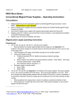
7 Claims, 15 Drawing Figures
TEMPRAU SENOR
WATERHEATING COIL 108
swam. DISK 4'SA3FE" 117
YNERMOSUKT
J2
JJ
ELCTRI HEAYING COIL
U.S. Patent 1141.22, 1986
VSheetl 0f5
4,602,145
US. Patent Jul. 22, 1986
Sheet2_o'f5
,
I
,
VENT TUBE
.
i
~
’ PRESSURE
RELIEF
I
CHAMBER _
w
(
39/
107
1
TIT
[I
,: ?
I
do 4011:
|
I
lr___1
l
|
I
r
J06
93%
10m. ‘
J7
__>
4
If?
2 VALVE
/
SPEED
I
4,602,145
E:
U
:5‘I ‘I
27
—
J05 ‘
//
| l
I
I
:5
l I
I
ill-“4:;
'
l
1
v
|
_ s=
93
1
I
SOLENOID
! 109 _[
,
V 133/‘
lcuEcxgfih
I VALVE
35’
‘
94
+__
I
\lrvégf
'35
if}:
r.
' Fl" ____ /
I
.
I
3 a2
\ 5:34 .
L-____-_-_-_______-__J
jigigj?
I J39
0
14a
’
.
1'20
____-/
,1, /2
'
Ill.‘M
130
'
‘US. Patent Juxl.22, 1986
Sheet3 of5 HOT
WATER
OUT
T
4,602,145
COLD
WATER
IN
T’ MUCH
100
{01
31
29/]
J03
TEMPERATURE
27
SENSOR
WATER
HEATING
COIL
J02
BIMETAL
DISK
SAFETY 49
THERMOSTAT
4
1-16’
7\
£0
5'9 T
if”
54
:6’
d1?
‘5]
5
JJ/
/
J5
J7
ELECTRTC
x5’
HEATING
con.
//'9
/7
2§
1,40, .1410 j
J6
5
jg
145
i
15,0
/_
US. Patent Jul. 22, 1986
_Sheet40f5
4,602,145
,?ga
TH ERMOSTAT
l
J0 45/,’
ALTERNATE SAFETY-’
THERMOSTAT LOCATION
U.S. Patent Jul. 22, 1986
|
I
l|
l
:
CHECK
133
VALVE SOLENOID WATER
|
!
F
|
-
95’
INLET VALVE
6'3
Sheet5of5
4,602,145
1
4,602,145
TAP-OFF HOT WATER SYSTEM FOR ELECTRIC
BEVERAGE MAKING DEVICE
BACKGROUND AND SUMMARY OF THE
INVENTION
The invention relates to a beverage-making device
which constitutes an improvement over the prior art,
particularly directed to those devices which automati
cally brew coffee.
In such devices, a water supply line is in direct com
munication with an inlet valve for on-demand admit
tance of cold water to a water-heating container in
which a constant source of hot water for brewing is
available. The inlet valve is electrically operated to
open for a preset brewing cycle equal to the amount of
time required to provide sufficient liquid to ?ll a receiv
ing decanter, such as a coffee pot.
A running thermostat senses the temperature in the
water container and electrically communicates with a
2
vate the heating element, would be a signi?cant
achievement.
Running thermostats are typically connected to an
enlarged sensing bulb by means of a thin capillary tube.
The bulb end is usually positioned at the lower half of
the container. The capillary tube must therefore extend
downwardly into the container to reach the bulb end. A
long guide sleeve is used to hold the bulb in place. The
guide sleeve is attached to the cover and extends down
wardly into the container to surround and protect the
capillary tube and the full length of the enlarged bulb
end. Usually, guide sleeves are secured to the bottom of
the heating coil so that the bulbs are ?xed in the proper
orientation. De?ciencies in this conventional arrange
ment have been encountered. Firstly, the enlarged bulb
end is limited to only sensing temperatures in the vicin
ity of the bottom half or third of the container. Temper
atures at the upper portions are not detected, and may in
fact be suf?ciently high to brew coffee without further
activation of the heating coil. It would be considerably
more advantageous to detect the mean temperature of
coiled, or looped, heating element so that the constant
the entire water volume. Secondly, conventional en
desired temperature is maintained.
larged bulb thermostats have a temperature-sensing
Water systems for admitting cold water to the con
spread of about 6°—8° F. Thereby, the heating element is
tainer include inlet tube means for dispensing the in 25 not quickly activated when the water becomes too cool
and, once activated, will unnecessarily remain on for a
coming water at the bottom of the container. As the
period of time after the water has reached the desired
cold water enters, displaced volumes of hot water at the
temperature. A thermostat arrangement that reacts to
top of the container are siphoned from the container to
smaller temperature changes would be economically
a brewing chamber, which is manually pre-?lled with a
bene?cial, since the heater would be activated soon
load of fresh ground coffee. As incoming water reduces
after the water falls below the usual brewing tempera
the water temperature in the container, the running
ture of 205° F. and then de-activated very shortly after
thermostat senses this lower temperature and activates
this is attained.
the heating element. The heating element remains ener
gized until the thermostat senses that the required water
temperature has been reached. With high capacity elec
tric heating elements, a substantial temperature increase
occurs over a short period of time. Should the running
thermostat fail in the on position, a so-called “run
away” condition will result whereby the heater will
stay energized. Thereafter, the heating element will
quickly evaporate the water and reach a dangerously
high temperature. In order to prevent overheating,
conventional systems include high limit thermostats. A
The guide sleeve arrangements in the prior art have
hindered maintenance procedures. In order to remove
the thermostat and bulb for repair, the cover has had to
be removed in order to disconnect the guide sleeve
from the heating element. It would be a great aid to
repair personnel to eliminate the need for a guide sleeve
and provide a running thermostat, capillary tube and
sensing tube that are completely disengageable from the
device without requiring other components, such as the
cover, to be disconnected or disturbed. A self-support
ing sensing means would greatly advance the solution
high limit thermostat serves to de-activate the heating 45 to this problem. Savings in maintenance time and repair
element when excessive temperatures are sensed. This
costs would be made.
safety feature is particularly useful when someone has
inadvertently failed to fill the water container prior to
initiating a brewing cycle. Without this feature the run
ning thermostat would blindly sense the ambient air
temperature inside the empty container. In response, the
heating element would continue to operate until reach
ing a dangerous “red-hot” condition.
customarily, the hot watar container is provided
with a hermetically sealed cover which supportively
accomodates the aforesaid siphon, running and high
limit thermostats, and inlet tube means, as well as the
terminals for the heating element. A drawback to this
typical arrangement is that only the temperature at the
Automatic beverage-making devices have also in
cluded means for dispensing hot water for making tea,
instant soup and the like. In the past these systems sim
ply drained hot water directly from the water con»
tainer. By extracting a volume of hot water from the
container, the brewing capability of the device is dimin
ished. Should a contemporaneous brewing cycle be
desired, the container must ?rst be re-?lled with colder
inlet water and then heated to elevate the temperature
of the water to the necessary brewing level. The re-?ll
ing step has usually been initiated by the provision of a
?oat switch arranged in the upper portion of the con
tainer which detects the drop in the water level. The
cover is sensed by the high limit thermostat. As a result, 60 inlet valve is electrically controlled by the switch
an excessively high temperature at lower portions of the
which signals it to open until the ?oat is satis?ed. Due
container, localized near the heating element, can some
to lime build-up the switches can close and become
times occur while the cover remains relatively cool.
The remote disposition of a high limit thermostat at the
inoperable. A hot water system that eliminates the need
for a ?oat switch would be a significant advance in the
container cover is inherently inefficient for detecting 65 art. It would also be a valuable improvement to provide
these temperature ?uctuations at the bottom half of the
container. A thermostat system which can immediately
a hot water system which does not borrow from the
water in the container but still makes hot water instanta
detect this dangerous condition, and promptly de-acti
neously available for these other purposes.
3
4,602,145
4
In order to distribute the siphoned hot water over the
cess to other components inside the device. It would
coffee grounds, typical beverage-making devices utilize
accordingly be of signi?cant value to provide a non
welded bottom drain system which avoids corrosion
and leakage problems. In addition, it would be advanta
geous for the drain system to be disengageable to permit
easy access to the interior of the device for the repair, or
resiliently biased spray means over which the siphoned
water is directed. The spray means is usually a flat,
perforate disk. Other devices have used a showerhead
type arrangement wherein a siphon tube nozzle ?uidly
communicates with a spray means that is concave
replacement, of mechanical and electrical components.
rather than disk-shaped. Spray means, in either form,
provide for sprinkling hot water over the coffee
grounds, which are disposed in the brewing basket, or
beverage-making devices of the type described, which
chamber, therebelow. For effective brewing to take
place, a “lazy” drip from the spray means is preferred
for a uniform distribution of hot water over the ground
coffee. A common problem, particularly with ?at spray
disks, has been that the siphoned water is too forcefully
emitted in streams through a series of disk ori?ces
which create an equal number of holes bored into the
The present invention offers an improvement for
satis?es the needs set forth above. The invention may be
brie?y summarized as comprising, in part, a safety ther~
mostat arranged with the container generally near the
heater, which facilitates the prompt detection of exces
sive temperatures long before the cover becomes over
heated. Thereby, a temperature increase can be immedi
ately sensed in order to de-activate the heating element
prior to reaching a dangerous condition.
mound of coffee grounds. Quite oppositely, the desired
An improved running thermostat system is provided,
drip phenomenon is an even flow over the grounds. It
would therefore be of great value to provide a moder
which senses the mean temperature of the entire volume
of water and has a more precise temperature-sensing
ately paced gravity drip system which eliminates indi
vidual spray streams through the disk ori?ces onto the
ground coffee. Spray disks also require cleaning due to
the accumulation of lime deposits and other sediments
spread than found with previous devices. The thermo
stat communicates with the water by means of a self
supporting elongate sensing tube that extends for sub
stantially the full height of the containerand is con
found in water lines. As a result, the disks need to be 25 nected to the thermostat by means of a capillary tube
render the disks removable, but are inadequate for
disposed outwardly of the cover. The unique thermo
stat and sensing tube arrangement is independently re
movable from the beverage-making device without
achieving a tight engagement therebetween. A tight
disturbing the container cover or any other compo
seal between the periphery of the spray disk and mount’
nents.
removed for cleaning. The usual resilient connections
between spray disks and associated mounting collars
ing collar is highly desirable so that the siphoned hot
water will not leak around the edges of the disk, but will
The improvement further includes a separate hot
water system for heating and continuously discharging
be emitted only through the ori?ces.
hot water independently of the siphoned brewing wa
Accordingly, a more effective interconnection be
tween a spray disk and mounting collar would be a
ter, but at a temperature substantially the same as the
signi?cant improvement over the foregoing devices. A
positively locking connection would avoid the disad
vantages of the resilient connections found in the prior
art. It would also be bene?cial to provide a tight sealed
engagement that also snugly lodges a flexible gasket
between the outer edge of the disk and the collar.
Thereby, edge leakage would be prevented and a ran
brewing water heated in the water container. The hot
water system has separate tap-off means for receiving
water from said source of cold water that is upstream of
the inlet valve for the hot water container. An inlet pipe
extends upwardly from the tap-off means and ?uidly
communicates with a receiving tube of a continuous
tubular water coil means arranged within said hot water
container and immersed therein. The inlet, pipe and
receiving tube are joined at a ?tting through the cover
of the hot water container. Thus, the volume of the hot
bution of hot water over the coffee grounds.
For standard size automatic beverage-making de 45 water in the water coil means is fluidly separated from
the brewing water. The water coil means includes an
vices, the hot water container normally holds at least
outlet tube extending upwardly therefrom which con
three times the volume of a conventional coffee pot and
veys hot water into a discharge pipe means that is joined
usually takes the form of cylinder having a greater
to the outlet tube at a second ?tting associated with and
height than width. Cleaning these relatively large con
through said cover means. The discharge pipe extends
tainers in necessary for taste and sanitary reasons. In
away from the cover and terminates in a manually oper=
order to remove sedimentation, such as lime deposits,
able water faucet arranged to dispense hot water out
the prevailing technique involves operating the bever
dom drip pattern attained for the preferred even distri
age'making device for several cycles with a de-liming
solution pumped through the container. Often, sedi
wardly of the beverage-making device. The faucet may
be selectively opened to extract water from the water
ments at the container bottom are not dissolved and
must be manually removed. In a more rudimentary
coil means independently of the siphoned brewing
cleaning method, the container is simply tipped over to
Prior art devices have failed to provide a separate bot
the water coil takes place so that the water faucet, when
opened, is able to continuously deliver water at a tem
perature substantially the same as said interior of the hot
water container. In other words, the water tapped from
the source of cold water is heated to the desired temper
tom draining system, probably due to the problems
encountered with attaching drain tubes. The customary
ature by the time it travels through the hot water coil
means and is thereafter dispensed from the faucet.
empty the water. The latter is clearly an awkward and
undesirable technique. A bottom drain, which allows
the container to be fully emptied, would be preferable.
water in the container. Continual heating of the water in
Also, an improved spray disk assembly forms part of
manner of affixing drains to metal containers is by weld
ing. A disadvantage to such ?ttings is that the welds 65 the invention. The assembly eliminates resilient attach
ment and instead securely, but removably, looks a spray
corrode and result in leakage. Welding also creates a
disk to a mounting collar above the brewing chamber.
?xed drain connection which impedes removing the
The disk is easily removed with a simple twisting mo
container for repair and otherwise generally limits ac
5
' 4,602,145
tion without the need for tools. The improved spray
6
disk assembly includes a sealing gasket which is tightly
held against the mounting collar so that leakage around
FIG. 9 is a sectional view of a check valve provided
for the hot water system as shown in FIG. 2;
FIG. 10 is another schematic view of the entire water
the periphery of the disk is eliminated. A series of ori
?ces extend through the disk but a direct spray through
each is avoided, and a random “slow-drip” for effective
matically showing an alternative embodiment for the
tap-off hot water system;
brewing is obtained.
A unique container draining system is additionally
provided which associates with an aperture at the bot
tom of the hot water container. The system includes a
?anged drain ?tting partly arranged interiorly of the
container and partly extending through the aperture to
flow system of the beverage-making device, diagram
FIG. 11 is a sectional view of an alternate combina
tion check and relief valve provided for use in the hot
water system shown in FIG. 10;
FIG. 12 is an exploded perspective view of the im
proved spray disk assembly as shown in FIG. 2;
FIG. 13 is an exploded perspective view of a portion
of the bottom drain system as shown in FIG. 3;
FIG. 14 is a side view of an alternate looped heating
be thread-engaged with an elbow and coupling assem
bly in a tightly sealed connection. A conventional valve
is connected to the coupling means and is manually 5
element usable in conjunction with the invention; and,
operable to facilitate emptying the water container. The
FIG. 15 is a front view of the heating element as
system eliminates the problems with welding and af
shown in FIG. 14.
fords quick disengagement from the container to allow
easy access to the interior of the device.
DETAILED DESCRIPTION OF THE
PREFERRED EMBODIMENT
BRIEF DESCRIPTION OF THE DRAWINGS
Introduction
The improved beverage-making device is described
in conjunction with the following ?gures in which like
FIG. 1 is a perspective view of the exterior of a cof
reference numerals are used throughout to identify the
fee-making device 10 which has a generally well-known
25 design and includes an upper housing 11 and lower
same components, wherein:
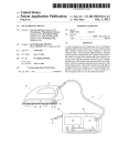
FIG. 1 is a perspective view of a beverage-making
housing 12. A brewing chamber 13 is removably held
device having the improvements of the invention
by a conventional slide track means 14 in position for
housed therein;
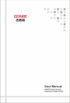
FIG. 2 is a schematic view of the entire water flow
system for the beverage-making device of FIG. 1, dia
grammatically showing the tap-off hot water system,
spray disk assembly and bottom drain system of the
invention;
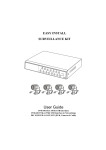
FIG. 3 is a composite vertical cut-away section and
elevational view of portions of the improved beverage
making device of FIG. 1 showing the hot water con
tainer and container cover cut-away to expose, in eleva
tion, the safety themostat arrangement to one side of the
container, the bottom drain system at the bottom of the
container, the electric heating coil having a pair of
terminals mounted at the cover, the water coil of the
hot water system having inlet and outlet tubes mounted
by means of compression ?ttings at the cover, and the
receiving hot water siphoned from a heated tank dis
posed inside lower housing 12. A decanter, or coffee
pot 15, is stationed on a warmer 16 and collects incom
ing brewed coffee from the chamber. The warmer is
activated in the usual way by a switch 17. To keep
previously brewed portions of coffee warm, the upper
housing 11 includes two warmers 18 and 19. A decanter
35 15 is ?lled with coffee and is shown stationed at warmer
18. The coffee maker 10 may also employ an auxiliary
warmer unit 16A of conventional design, shown in
phantom lines in FIG. 1.
The coffee maker 10 is operated by means of a con
trol panel 20, which includes a main switch 21, a brew
ing cycle switch 22 and a ready light 23. The switch 21
activates the electrical system of the coffee maker- >
whereby a heating element and thermostat arrangement
sensing tube for the running thermostat system broken
away just below the cover; other components of the 45 cause a stored volume of water to be heated to a desired
brewing temperature, as will be hereinafter described.
beverage-making device, including the locking means
A ready light 23 is illuminated when the system is ready
for mounting the sensing tube to the cover, the running
to
provide hot water for brewing coffee. At that point,
thermostat, and a bracket for alternately mounting a
a brewing cycle may be initiated by depressing the
safety thermostat on the cover, are deleted from FIG. 3
switch 22, whereupon the hot water is siphoned onto
for purposes of clarity and explanation, and are shown
coffee grounds contained within the chamber 13.
in detail in the other Figures.
FIG. 4 is a plan view of the hot water container cover
assembly, including the improved running thermostat
Warmers 18 and 19 are operated by the switches 24 and
25 located near the top of the panel 20.
The control panel 20 further includes a hot water
system associated therewith and the inlet and outlet
55 faucet 26 extending outwardly therefrom, which pro
openings for the water coil shown in FIG. 3;
vides means for dispensing water from the tap-off water
FIG. 5 is a front elevational view of the improved
system of the invention, as will be described below.
safety thermostat arrangement as shown in FIG. 3;
FIG. 2 is a schematic drawing of the internal compo
FIG. 6 is a sectional view taken along lines 6-6 of
nents of the coffee maker 10. The upper housing 11 and
FIG. 4 showing the locking assembly for mounting the
sensing tube of the running thermostat system to the 60 lower housing 12 are shown in dashed lines. It will be
container cover and a conventional bracket used for
mounting a safety thermostat at the cover;
understood that the electrical circuitry for the device 10
is provided in a conventional manner, such as found in
the wiring system for Model Nos. 8714 and 8715 made
FIG. 7 is a perspective view of the mounting bracket
by Bloom?eld Industries, Inc., Chicago, Ill. The rela
for the running thermostat as shown in FIG. 4;
FIG. 8 is a sectional view taken along lines 8—-8 of 65 tionships of the various components in the wiring
scheme, including the improved safety thermostat ar
FIG. 4 showing the outlet cap and baffle used for con
rangement and the running thermostat system of the
trolling the discharge of brewing water siphoned from
the container into a siphon tube;
invention, are intended to be connected in the circuit in
7
4,602,145
8
this known manner, and the circuitry therefore forms
no part of the invention.
With reference to FIGS. 24, it will be seen that the
coffee-making device 10 includes a hot water container,
or tank, 27 which is initially ?lled with a predetermined
volume of water. In the illustrative embodiment, the
tank 27 holds approximately one gallon when ?lled to
the intended maximum level of about one-half inch
below the top of the container. When the switch 21 is
on, the temperature of the water inside the tank 27 is
monitored by an improved running thermostat system
28. The required brewing temperature is in the range of
from about 200° F. to about 205° F. To facilitate heating
the water, a sheathed electrical heating coil 29 is ar
ranged within the tank and is in electrical communica
cover 30 and has a central aperture 42’ into which the
tion with the running thermostat system 28. When the
running thermostat system 28 detects that the water
temperature has fallen below the desired range, the
decanter 15. It will be understood that the calibration of
the timer means will preferably be made so that the
portions of water absorbed by the grounds and 10st in
system closes a circuit and activates the heating coil 29
the form of steam are taken into account in order that
siphon tube 42 is attached to be in ?uid communication
with the hot water. An outlet cap 91 and a baffle 92 are
welded at the undersurface of the shoulder 90 in a typi
cal construction whereby the rising, displaced hot
water is controlled in its passage upwardly through the
aperture 42’ into the siphon tube. The siphon tube 42
slopes downwardly from the top of the container and
discharges the hot water into a spray disk assembly 43,
which distributes the water over the coffee grounds in
brewing chamber 13.
Following the timed sequence, the valve 33 is closed,
and the heated water within the brewing chamber 13
bathes the coffee grounds therein, whereby brewed
coffee seeps from the chamber, by gravity, into the
until such time that proper brewing temperature is 20 the decanter is ?lled to the necessary level.
In the event that pressure is built up within the con
achieved within the container 27. The ready light 23 is
electrically controlled by the running thermostat sys
tainer 27, a vent tube 44 is affixed to the cover 30 at the
tem and is not illuminated until the heating element is
aperture 44’ to communicate interiorly of the container
27. The vent tube extends upwardly from the cover 30
to enter the basin 37 for discharge therein. Accordingly,
de-activated.
As best viewed in FIGS. 3 and 4, a cover 30 closes
the open top of the tank 27 and is hermetically sealed
thereto by means of a gasket 31 disposed between the
upper rim of the tank and the peripheral lip of the cover
in a known manner. The hot water is thereby safely
sealed within the tank.
excess water pressure will be relieved into the basin and
be safely drained back into the container via the drain
sump 38.
Since the cold inlet water decreases the tank water
temperature, the running thermostat system 28 will
When freshly brewed coffee is desired, the brewing
activate the electrical heating element 29, in the manner
basket, or chamber 13 is lined with ?lter paper and then
manually loaded with a predetermined amount of
ground coffee. The coffee pot 15, as shown in FIG. 1,
may then be placed onto the warmer 16 in position to
receive brewed coffee from the chamber 13. Brewing
mentioned above. Following a brewing cycle, rapid
heating sometimes occurs with certain high capacity
heating elements. If the running thermostat is faulty and
sticks in the on position, a back-up safety provision is
needed to de-energize the heater before the water com
cycle button 22 is then pushed to initiate the brewing
pletely boils away and the element overheats. In FIG. 4,
a typical arrangement for a safety thermostat 45 is
shown in phantom lines and provides a means for de
tecting an overheating of the cover 30. A standard
bracket 46, shown in solid lines, offers the mounting
means for the safety thermostat 45. In coffee-making
devices of the type described, the running thermostat
and the safety thermostat are connected in series with
sequence.
The water flow system for providing brewing water
to the chamber 13 is best understood with reference to
FIG. 2, wherein a water inlet pipe 32 is arranged at the
bottom portion of the housing 12 and is connected to a
water supply line (not shown). The inlet pipe 32 is in
?uid communication with a solenoid valve 33 which is
operated by a conventional timer means that begins its 45 the heating element whereby the safety thermostat will
override the running thermostat to de-activate the heat
sequence when the button 22 is activated. The timer is
ing element when the cover reaches these overheated
calibrated to open the valve 33 for the period of time
temperatures. Generally safety thermostats are manu
required to admit a volume of water suf?cient to ?ll the
factured to have an open temperature of about 226° F.
coffee pct 15. The valve 33 includes a cleanout 34 to
This conventional arrangement has been satisfactory for
enable it to be backflushed when lime deposits accumu
heating elements of 1800 watts or less, such as the
late at the valve. The ?ow rate from the valve 33 is
looped elements 118 and 118’ shown in FIGS. 14 and
controlled by an internal flow control valve 35, which
in the exemplary embodiment permits 0.75 gallons per
minute to pass into an inlet pipe 36. The inlet pipe 36
directs the cold water upwardly into a basin 37 disposed
within upper housing 11. The basin 37 is formed to have
a drain sump 38 for draining incoming water into a tube
39. Tube 39 directs the water through an aperture 39' of
15, and therefore may be practiced with the other fea
tures of the invention herein described for these lower
capacity elements. Therefore, the cover 30 is preferably
provided with a bracket 46 in the event that the coffee
maker 10 is provided with the lower capacity heating
elements. However, the arrangement of the thermostat
45 has been found to be inef?cient for the higher capac
cover 30 and terminates thereat to open into a funnel 40.
Funnel 40 is af?xed to the bottom of the cover around 60 ity elements which can quickly overheat the lower
portions of the container 27 long before the cover 30
aperture 39’. An inlet tube 41 is connected to the funnel
becomes equally hot.
40 and extends downwardly into the container 27 to
discharge the cold water near the bottom of the con
tainer. The entering cold water displaces an equal vol
Improved Safety Thermostat Arrangement
With reference to FIGS. 3 and 5, an improved safety
ume of hot water near the top of the container 27 which 65
thermostat arrangement is shown for use with the high
flows into a siphon tube 42.
capacity heating elements and replaces the existing
With reference to FIGS. 4 and 8, it will be noted that
techniques, such as the thermostat 45 of FIG. 4. In the
a raised annular shoulder 90 projects upwardly from the
9
4,602,145
preferred embodiment, the heating coil 29 is a 230 volt,
4800 watt, ll loop coil. Other high capacity heating
10
means 61 located in positional correspondence with the
thermostat 47 along the front face of the housing 12, a
elements, similar to the heating element 29, may alterna
shown in FIG. 1. A small screwdriver, for example,
tively be provided, such as a 120 volt, 2000 watt coil
having 5 loops, or a 230 volt, 3500 watt coil having 8
may be used to push the button 62 and reset the thermo
stat for subsequent use.
loops.
The top loop of the coils is connected to a conven
tional terminal assembly T by a vertical section of the
heating element. The bottom loop of the coil is con
Improved Running Thermostat System
nected to a conventional terminal assembly T’ by a
The running thermostat system 28, which heretofore
has been generally discussed with regard to activating
and de-activating the heating element 29, will now be
vertical section of the element. Both of the terminal
assemblies T and T’ provide water tight connections
described in greater detail with reference made to
FIGS. 3, 4, 6 and 7. System 28 is an improvement over
with cover 30 at terminal openings 29A and 29B, as best
viewed in FIGS. 3 and 4.
previously known arrangements, particularly because
It will be observed that the loops of the coil 29 extend
annularly near the side of the container 27. At these
sensed. Also, temperature variation is sensed within a
locations rapid increase in temperature can occur. In
the beverage-making art because the device 10 is
the mean temperature of the entire water volume is
very narrow range. These are signi?cant advances in
solution of the problems with prior art systems, there is
thereby rendered considerably more efficient by only
provided a manually resettable thermostat 47 preferably
operating the heating element when necessary.
mounted adjacent the container 27 at or below the mid 20
The improved running thermostat system 28 includes
point thereof and generally close to the heating coil.
a thermostat 63 located at the cover 30. The thermostat
The thermostat 47 has an exposed bi-metal disk 48 dis
63 has an adjustable control shaft 64 that enables the
posed against the side of the container. In the exemplary
embodiment, the thermostat 47 is an Essex International
Controls Division thermostat Model No. 404-58 having
thermostat setting, and thereby the brewing water tem
perature, to be varied. Preferably, the thermostat 63 has
25 the operating capacity of a ROBERTSHAW Controls
an open temperature of 226° F.i9° F. The thermostat
Company thermostat No. K-944-12, or equivalent.
47 includes terminals 49 and 50 which are of the spade
Other suitable devices will be apparent to those skilled
type variety, whereby the thermostat 47 is wired to be
in the art. The thermostat 63 is affixed with a mounting
in series with the running thermostat system 28. The
flange 65 having a pair of engageable holes 66 and 67. A
thermostat 47 includes a mounting plate 51 affixed to a 30 cooperative mounting bracket 68, best shown in FIGS.
housing 52 of the bi~metal disk 48. The plate 51 extends
4 and 7, supports the mounting ?ange 65, and thereby
transversely to the terminals 49 and 50 and has side
the thermostat 63, at cover 30. The bracket 68 com
wardly-open notches 53 and 54 at opposite sides
prises a lower plate 69 integrally formed with a vertical
thereof. A cooperative bracket 55 is disclosed for the
plate 70, which includes a vertical slot 71, a horizontal
positioning of the thermostat 47 at the desired location 35 slot 72, and a central, upwardly open notch 73. The
along the tank 27. The bracket 55 is preferably made of
slots 71 and 72 correspond to the spacing of the holes 66
stainless spring steel and has a mounting foot 56 and an
and 67 of the mounting flange 65. Screw fasteners 74
upwardly extending long arm 57. The foot 56 is me
and 75 are provided to be received through the slots 71
chanically fastened by screws S to the bottom of the
and 72 and thereafter engaged within the holes 66 and
housing 12 and is made whereby to form an angle of 40 67 whereby to releasably hold the thermostat on the
greater than 90° with arm 57 before attachment in the
bracket. In this arrangement, the thermostat 63 is easily
coffee maker. The af?xation of the foot 56 to housing 12
removable from the bracket 68 by partially unthreading
disposes the arm 57 at right angles to the foot 56 and
the screws and thereafter simply moving the thermostat
thus arm 57 is spring biased toward the container 27 in
first upwardly to disengage the fastener 74 from the slot
order to urge the thermostat 47 against the container. A
71, and thereafter sidewardly to remove the fastener 75
mechanical fastening of the thermostat 47 to the bracket
from the slot 72. This removability is a signi?cant ad
55 is envisioned wherein the upper end of the arm 57 is
cut-out to form a seat 58 intermediate a pair of upstand
ing side ears 59 and 60. The ears 59 and 60 include holes
which, as would be understood, are spaced to align with 50
vantage for repair personnel since, unlike previous de
vices, these threaded fasteners need not be removed and
therefore cannot become accidentally dropped within
the housing of the coffee-making device during repair.
A short capillary tube 76 associates with the thermo
secure the mounting plate 51 to the bracket 55.
stat 63 in a conventional manner. However, the capil
Preferably, the thermostat 47 is positioned so that the
lary tube 76 does not extend downwardly into the con
bi-metal disk 48 contacts the side of tank 27 just slightly
tainer 27 to meet a bulb end, such as found in the prior
above the upper loop of the heating coil 29 where rising 55 art. Instead, a unique elongate and self-supporting sens
heat from the coil will create the hottest spot. If temper
ing tube 77, best viewed in FIGS. 3 and 6, extends
atures exceeding the thermostat capacity are created at
downwardly from the cover. The sensing tube 77 is
the bi-metal disk 48, as might occur when a defective or
joined to the capillary tube 76 interiorly of a fastening
stuck running thermostat fails to switch off and contin
assembly 78, shown in the sectional view of FIG. 6. The
ues to energize the heating element until ?nally all the 60 sensing tube 77 offers a great advance over the existing
water evaporates, the thermostat opens the circuit to
thermostat systems inasmuch as no guide sleeve is
de-activate the heater 29. The thermostat 47 is provided
needed. Further, the sensing tube need not be attached
with a manual reset button 62, which requires the opera
to the heating coil, which is customary with known
tor to make the necessary reset once the heater has been
guide sleeve systems in order for the bulb to be main
shut down. A manually resettable thermostat is prefera 65 tained in the proper vertical orientation at a speci?ed
ble for this safety system, but alternatively, a self-reset
depth within the hot water container.
ting thermostat may also be used. Access to the reset
The sensing tube 77 is hollow and is preferably made
button 62 is provided by a removably-capped peek hole
of stainless steel. A conventional oil is contained within
the notches 53 and 54 so that screw fasteners S’ may
4, 602, 145
11
the tube 77 and is in fluid communication with the capil
lary tube 76 as would be clear. Sensing tube 77 extends
downwardly within the coils of the element 29 and
terminates generally near the bottom thereof in a
crimped end 79. The tube 77 thereby extends for sub
stantially the full height of the container 27 and renders
the system 28 capable of detecting the mean tempera
ture of substantially the entire volume of water within
the tank. Existing capillary bulb devices usually have an
outer diameter of greater than 0.30 inches. Thus, a guide
sleeve of greater diameter is required to surround the
bulb end. In preferred form, the sensing tube 77 has an
outside diameter less than 0.30 inches and therefore
12
high capacity heaters because they tend to deteriorate
much more quickly than the lower capacity elements. It
will also be clear that the hot water is almost always
made available at the proper temperature for making
coffee. The capability of the system 28 to minimize this
activation time and keep the water at the desired tem
perature are significant bene?ts of the invention.
Tap-Off Hot Water System
The invention further provides a tap-off hot water
system which does not borrow from the water content
within the container 27 and requires no ?oat switch
means. With reference to FIGS. 2, 3 and 9, it will be
observed that the tap-off hot water system is generally
occupies a smaller space. It has been found that this
denoted
by reference numeral 93. A signi?cant feature
5
thinner construction allows the oil therein to be quickly
of the system 93 is that it taps cold water from the inlet
sensitive to the temperature changes whereby the tem
pipe 32 by means of a T-?tting 94 located upstream of
perature detected at the thermostat 63 is closely re?ec
the inlet valve 33. A check valve 95 is connected to the
tive of the temperature fluctuations within the tank. As
T-?tting 94 by a suitable connecting pipe means
a result, the system 28 is capable of responding to tem
perature change in a range of from about 2° to 3° F. 20 whereby a minimum water pressure is required before
water is introduced into the system. The check valve 95
spread and at least before a 6° F. change has occurred.
has a conventional construction, as shown by the sec
Existing systems are less precise and are responsive to
tional view thereof in FIG. 9, wherein a spring biased
spreads of about 6° to 8° F., or more.
valve 96 controls the passage of water from an inlet
Reference is now made to the locking means 78
chamber 97 into an outlet chamber 98. In the preferred
shown in the sectional view of FIG. 6. It will be seen
embodiment, the check valve 95 requires 2 psi. of
that the capillary tube 76 is soldered to a tapering upper
pressure to open.
end of the sensing tube 77 generally denoted by refer
Water conveyed through the check valve passes
ence numeral 80. A female ?tting 81 is weld-connected
straight through a T-?tting 99 into a tube 100 which
within and around an aperture 82 extending through the
cover 30. The ?tting 81 includes a centrally threaded 30 directs the cold water into a compression ?tting 101
sealingly arranged within an aperture 101’ at the cover
bore 83 which is thread engageable with a lock nut 84.
30.
The lock nut 84 is hollow whereby to permit the capil'
lary tube to pass therethrough and be joined with the
The important characterizing feature of the tap-off
tube 77 at the solder connection 80. At its lower end, the
hot water system is the arrangement of a water coil 102
bore 83 includes an inwardly extending annular shoul 35 within the container 27. The water coil 102, in preferred
der 85 forming a bearing seat within the ?tting 81. A
collar 86 is soldered around the upper end of the sensing
tube 77 generally below the solder connection 80 and
includes a peripheral shoulder 87. Between the periph
eral shoulder 87 and the annular shoulder 85, a water
form, is a hollow stainless steel tubing having about at
least an 8 ounce capacity. The coil 102 is concentrically
arranged above heating element 29 and spaced below
the cover 30 as shownin FIG. 3. Coil 102 includes an
upright cold water receiving tube 103 communicating
with the lowest loop of the coil and a shorter upright
hot water outlet tube 104 communicating with the top
most loop of the coil. The tube 103 is connected to the
nut 84 as it threads downwardly into engagement with
compression ?tting 101 below the cover 30 to be in fluid
the bore 83. Lock nut 84 also securely fastens the collar
87 within the ?tting 81 and thereby ?xes the sensing 45 communication with the tube 100. Cold water entering
from the tube 100 thereby circulates through the coil
tube 77 in the orientation illustrated in FIG. 3.
102 and is quickly heated due to the constantly main
It will be appreciated that the running thermostat
tained temperature of the water resulting from the on
system 28 is completely disengageable from the cover
and off activation of the heating element 29, as de
30 without the removal or disturbance of any other
components. Speci?cally, the thermostat 63 can be dis 50 scribed above.
It will be observed that in the preferred embodiment
engaged from the bracket 68 as explained, and by un
the water coil 102 includes 14 loops arranged in a heli
tightening the lock nut 84, the sensing tube, with the
cal formation wherein adjacent loops are in contact. No
capillary 76 attached thereto, may be drawn upwardly
need for additional heating of the coil is required since
out of the aperture 82 in a facile manner. When the need
to replace the thermostat 63 arises, repair is therefore 55 it is placed generally at the upper half of the container
tight sealing means is provided by a rubber gasket 88
and metal washer 89, which are compressed by the lock
expedited and maintenance costs are reduced. It is con
templated that replacement of the thermostat 63 will
not be required as often as with existing systems due to
the capability of system 28 to sense the mean tempera
ture of the water within a narrow temperature spread.
By quickly reacting to the water temperature changes,
the heater is activated before the temperature drops no
more than 6° F. below the usually desired brewing
temperature of 205° F. Furthermore, the heating ele
27 and is continuously surrounded by hotter rising
water circulating past the individual loops. A second
compression ?tting 105 is sealingly arranged within an
aperture 105' of the cover 30 and is connected to the
outlet tube 104 below the cover 30 and to a hot water
discharge tube 106 above the cover. The discharge tube
106 conveys hot water outwardly of the container 27 to
pass through a speed valve 107 associated therealong.
The speed valve 107 is manually operable to permit
ment will not remain activated as long, since as the 65 varying the water pressure therethrough, such as when
temperature is raised, the system 28 will react to de-acti
vate the element at no greater than about 6° F. above
the brewing temperature. This ef?ciency is critical with
there are changes in the water supply pressure entering
the inlet pipe 32. The outlet tube 106 extends generally
horizontally toward the control panel 20 and is con
13
4,602,145
14
nected thereat with a lever-action faucet 26, as best
viewed in FIGS. 1 and 2. The faucet 26 is preferably a
FIG. 11 shows a twin valve assembly 113 alterna
tively usable in the embodiment illustrated in FIG. 10.
conventional 100 p.s.i. to 150 p.s.i. faucet, well known
The twin valve assembly 113 includes, in a single hous
to those skilled in this art.
When hot water is needed for making tea, instant
soup, hot cocoa, etc., the faucet 26 is manually opened
and cold water flows inwardly from the inlet 32
through the inlet tube 100 into the coil 102 to force hot
ing, a check valve 114, a pressure relief valve 115, a
T-?tting 116 and an elbow 117, which respectively
replace the check valve 95, the pressure relief valve 110,
the T-?tting 99 and the elbow 111, shown in FIG. 10.
The check valve 114 and the pressure relief valve 115
are provided to open at the same respective levels of
water in the coil to be pressured outwardly thereof into
the tube 106 and dispensed via the faucet 26. Due to the
water pressure as described for the check valve 95 and
continuous heat transferred to the coil from the hot
the pressure relief valve 110. Thus, incoming water
water in the container and the unique helical coil ar
from the inlet tube section 100A is directed into the
rangement, by the time the cold water entering from the
section 100B through the T-?tting 116. When excess
inlet tube 100 reaches the outlet tube 104, it is as sub
pressure is experienced by the system, the relief valve
stantially as hot as the brewing water within the con 5 115 opens and directs water through the elbow 117 into
tainer 27. Thus, a constant source of hot water is readily
the over?ow tube 112. It is envisioned that the twin
available without the need to borrow from the contents
valve assembly 113 would be arranged within the sys
of container 27. It will be appreciated that there is no
tem 93 in substantially the same location as the T-?tting
need to provide any ?oat limit switches which are oth
99 shown in FIG. 10.
erwise required in conventional hot water systems that
simply drain the water tank to obtain hot water.
Since the water heated within the coil 102 will natu
In preferred form, the inlet and outlet pipe means for
the system 93 comprise standard one-quarter inch cop
per tubing but, of course, they may have a larger or
rally expand and increase the pressure in the system 93,
smaller size as needed.
the faucet 26 may experience pressures in excess of its
While the hot water system 93 has been described in
capacity and leak. Relief for this pressure is provided by
25 conjunction with a beverage-making device 10 having a
a expansion chamber 108, which is connected to the
transverse stem of the T-?tting 99 by a standard elbow
109, shown in FIG. 2. Any excess water pressure caused
high capacity heating coil 29, it should be apparent that
the unique design for the water coil 102 permits the
system to be equally suited for use in devices having a
by expansion in the coil 102 will therefore be relieved
through the tube 100 into the chamber 108 and prevent
leakage at the faucet 26, or for that matter, at any other
components within system 93.
The placement of the expansion chamber 108 is envi
sioned to be vertically within the lower housing 12 of
the coffee maker 10 generally at a corner thereof and
spaced from the container 27. In conventional housing
designs, the standard box-shaped lower housing affords
variety of heater arrangements. For example, the sys
tem 93 may be provided in combination with lower
capacity heaters, such as the elements 118 and 118'
(phantom lines) shown in FIGS. 14 and 15. The ele
ments 118 and 118’ each have a pair of terminals t and t’
which are capable of being secured to a tank cover in
substantially the same manner as the terminals T and T’
of the heating coil 29. The element 118 is a 100-120 volt
single loop heater having a 1300-1500 watt capacity,
particularly useful for standard electrical circuits in the
suf?cient space for stationing the expansion chamber
United States, Canada and Japan. The element 118’ is a
108.
40 220-240 volt single loop heater having an 1800 watt
An alternate embodiment of a pressure relief means
capacity for use in the standard electrical circuit sys
for the system 93 is disclosed in FIG. 10. The same
tems found in Europe. Each heating element is formed
reference numerals are used to denote the system 93 in
to have a narrow elongate J-shape (FIG. 14) which is
both FIGS. 2 and 10, with the exception that in FIG. 10
adapted to be arranged within a hot water tank gener
the inlet tube comprises two sections, denoted 100A and 45 ally at the central long axis thereof. It will be under
100B, and it will be observed that these A and B sec
stood that the coil 102 is capable of being disposed
tions are created by re-positioning the T-?tting 99. In
within the tank to circumscribe either heater element
118 or 118' whereby the system 93 operates in the same
this alternative, the expansion chamber 108 is deleted
and the T-?tting 99 is re-located upwardly along the
way as explained above.
inlet tube section 100A generally adjacent the cover 30.
Clearly, the coil 102 may be provided to have a dif
The stem of the T-?tting is oriented in the opposite
ferent diameter and number of looped coils so to be
direction with respect to that shown in FIG. 2. In this
appropriately sized for various cylindrical tank dimen
embodiment, the stern of the T-?tting is engaged with
sions. A wide variety of loop shapes are also intended to
the inlet tube section 100B, which directs the water
fall within the scope of the invention. It will be apparent
room at either of its rearward corners which provide
?ow into the coil 102 as explained above. The other arm
of the T~f1tting is connected to a standard pressure relief
valve 110. The relief valve 110 preferably has an open
pressure capacity of about 100 p.s.i. to 110 p.s.i., so that
that the water coil is not limited to a helical con?gura
tion and may be suitably shaped for use in containers
that are polygonal in cross-section.
it will open at a pressure level below the pressure capac
Improved Spray Disk Assembly
ity of the faucet 26, as would be clear.
Downstream of the pressure relief valve 110 a suit
With reference to FIGS. 2 and 12, the improved
spray disk assembly of the invention is shown and is
able elbow 111 connects the valve to an over?ow tube
generally denoted by reference numeral 43, previously
112. The overflow tube 112 extends to pass through the
mentioned above. FIG. 12 is an exploded perspective
wall of the basin 37 for discharge of over?ow water into
view of the assembly 43, which comprises a mounting
the basin. Thus, the system 93 will be relieved of exces 65 collar 119 associating with a ?exible gasket 120 and a
sive pressure by discharging it into the container 27 via
spray disk 121. The mounting collar 119 is affixed at an
the drain sump 38 in a similar manner to the action of
undersurface 122 of the upper housing 11 around an
the vent tube 44.
opening 123 therethrough, which communicates with
15
4,602,145
16
.
the siphon tube 42. The collar 119 comprises a circular
the container 27. A threaded stem 139 is integrally
top plate 124 having a central opening 123’ arranged at
the opening 123. In the exemplary embodiment, the top
plate 124 is welded to the undersurface 122 and has a
formed with the seat 138 and extends downwardly
through the drain hole 134. The bottom of the seat 138
is beveled at 140 and the container bottom 135 includes
depending peripheral side wall 125 formed therewith.
a cooperatively depressed annular bevel 140’ around the
The side wall 125 includes a pair of diametrically op‘
posed bayonet slots 126 which downwardly open at 127
drain hole 134 whereby the seat 138 can be flushly and
tightly sealed at the bottom 135.
A coupling means comprising a female elbow 141 is
and upwardly terminate in horizontal portions 128. The
provided for engagement with the external threading of
gasket 120 is provided with an outside diameter substan
tially equal to the inside diameter of side wall 125 and 0 the ?tting 136. In order for the elbow 141 to threadably
has a height slightly less than the height of the side wall
engage the ?tting 136, the drain hole 134 and the stem
and suf?cient to extend from the top plate 124 down
139 have ?at sides 142 and 143, respectively. Thereby,
wardly to meet the horizontal portions 128.
the bottom 135 is cooperative to act like a wrench and
In the past, a siphon tube simply discharged onto a
prevent the ?tting 136 from rotating in order to facili
spray disk which was resiliently held by a mounting
tate the engagement, or disengagement, of the elbow
collar. The improved assembly 43 provides rigid lock
ing and tight sealing between the mounting collar 119
and the disk 121 whereby leakage about the periphery
141.
The elbow 141 includes an upper annular seat 144 for
of the disk 121 is avoided. The disk 121 is best described
as a generally circular plate having a diameter sized to
snugly ?t within the side wall 125 and includes a pair of
oppositely extending radial tongues 128. The tongues
128 include ?at sections 129 adjacent the disk edge and
terminate outwardly in U-shaped portions 130. By
grasping the U-shaped portions 130, the ?at sections 129
are engageable at the bayonet slots 126 by moving the
disk 121 upwardly to dispose the sections 129 within the
openings 127. Thereafter, the disk is rotated in a clock
wise direction to securely lodge the sections 129 within
the horizontal portions 128. Thereby, the gasket 120 is
sealed against the top 124 and the disk 121 whereby to
prevent leakage between the disk and the side wall 125.
The disk 121 is provided with a series of ori?ces 131
which are arranged to form a central imperforate por
tion 132. Water, discharging from the container 27
through the siphon tube 42, drips onto this imperforate
portion 131 and flows outwardly therefrom to ran
domly drip through the ori?ces 131. As previously
described, the flow control valve 35 preferably limits
the inlet rate of water ?ow to the tank 27 to about 0.75
gallons per minute. As a result, water is siphoned from
25
the accommodation of an O-ring 145 therein. Upon
thread engaging the elbow 141 to the drain ?tting 136,
the O-ring 145 is compressed to seal against the under
surface of the annual bevel 140' to prevent leakage
therearound. A standard male coupling 146 engages the
outlet side of the elbow 141, and at its opposite end
engages with a reducer coupling 147. A third coupling
148 engages the other side of the reducer coupling 147.
Lastly, a manually operable drain cock 149 engages the
outlet end of the coupling 148. The coupling assembly
146-148 is of a suf?cient length whereby to dispose a
drain cock 149 adjacent the housing 12. An access cut
out (not shown) is provided through the housing so that
the drain cock can be easily reached when needed. In
FIG. 3, a hose 150, shown in phantom, is connected to
the drain cock in order to drain the Water from the tank
27 into a sink, pail, etc.
In conventional beverage-making devices, a remov
able rear panel is provided so that access to the internal
components can be obtained for maintenance and re
pair. By the provision of the drain system 133, it will be
clearly understood that the elbow 141, the coupling
assembly 146-148 and the drain cock 149 are fully re
movable as a unit by simply disconnecting the elbow
141 from the drain ?tting 136. Thus, not only can the
system 133 be repaired, if necessary, but other sur
The tight seal created by the locking engagement of 45 rounding components within the device 10 may be eas
ily reached by simply removing, and later easily replac»
the tongues 128 within the bayonet slots 126 assures that
ing, the system.
the water is directed through the ori?ces and is pre
The system 133 requires no welded connection with
vented from leaking around the edges of disk 121.
the tank 27, and therefore the corrosion problems inher~
When cleaning is required due to the accumulation of
ent in previously known welded ?ttings is totally elimi
lime, or other sediments, the operator can easily discon
nated.
nect the disk by grasping the U-shaped portions 130 and
then twisting the disk 121 counterclockwise to disen
ACHIEVEMENTS
gage the sections 129 from the slots 128. This locking
An improved beverage-making device has been dis
feature of the assembly 43 will thereby be appreciated as
closed which safely and ef?ciently controls the heating
providing a rigid, but removable, securement between
element for the hot water container by the provisions of
the disk 121 and the mounting collar 120, while com—
an improved safety thermostat arrangement and an
pletely eliminating any reliance upon resilient connec
improved running thermostat system. Additionally, the
tions which have proven unsuccessful heretofore.
invention includes a tap-off hot water system which
Drain System
60 dispenses hot water without borrowing from the hot
water container. Further, the invention achieves the
A unique drain system 133 is provided for emptying
goal of providing an improved spray disk assembly that
the hot water container of the beverage-making device
offers a tightly sealing locking means for the disk
10 and is best viewed with reference to FIGS. 3 and 13.
whereby the brewing water is evenly and moderately
The drain system 133 associates with a central drain
hole 134 at the bottom 135 of the container 27. The 65 distributed over all the coffee grounds contained in the
the tank 27 in a moderate pace whereby the water pres
sure emitted from the siphon tube 45 will be measured
to be less than one inch of mercury.
system 133 includes a drain ?tting 136 which has an
brewing chamber. Moreover, the invention provides
open bore 137 for receiving drainage therethrough and
an upper annular ?anged seat 138 residing interiorly of
means of a unique bottom drain system removably en
for the complete draining of the hot water tank by
17
4,602,145
18
gaged at the bottom of the container in a tightly sealing
non-corrosive connection.
with said cover means whereby the discharge pipe
means is in ?uid communication with said outlet tube,
While the foregoing description of the invention has
said discharge pipe means extending from said cover
been directed toward a preferred embodiment therefor,
means and having a water faucet means arranged there
it will be apparent to others that various modi?cations 5 along remote from said hot water container; said water
and alternative embodiments fall within the scope of
faucet means being operable to dispense hot water from
this disclosure and the claims appended hereto.
said discharge pipe means, said water coil means pro
viding a flow path suf?ciently long that the water ?ow
What is claimed is:
1. In a beverage-making device of the type having a
hot water container for holding a volume of water and
ing therethrough from said receiving tube to said outlet
tube is heated to substantially the same temperature as
arranged with a removable cover means sealed there
the heated water in the container for discharge through
said faucet for an unlimited duration and independently
of the water discharging from said outlet means.
over, the hot water container being in communication
with timed inlet valve means for admitting a predeter
mined amount of cold water into the container, the inlet
valve means ?uidly associating with a source of cold
2. The improvement as in claim 1 wherein said water
coil means is arranged to have a major portion thereof
generally within the upper half of said water container
and comprises a continuous helical tubing having a
water, thermostatically controlled electric heater means
arranged within said container to be bathed by said
volume of water and adapted for heating said volume of
plurality of closely spaced generally horizontal loops, a
bottom loop thereof formed with said upwardly extend
ing receiving tube and a top loop thereof formed with
said upwardly extending outlet tube.
water to a predetermined constant temperature within
the container, and outlet means communicating through
said cover means interiorly of said hot water container
for siphoning hot water from the container and convey
ing said heated water to be discharged therefrom re
3. The improvement as in claim 1 wherein said ?tting
mote from said hot water container, the improvement
comprising a separate hot water system for heating and 25
means comprise sealed compression ?ttings arranged at
apertures extending through said container cover
means.
continuously discharging hot water independently of
4. The improvement as in claim 1 wherein said hot
water system includes pressure relief means whereby to
relieve pressure in the water coil means.
5. The improvement as in claim 4 wherein the pres
sure relief means comprises closed expansion chamber
the outlet means at a temperature substantially the same
as said volume of water in said container; said hot water
system having separate means for receiving water from
said source of cold water upstream of said inlet valve
means, upwardly extending inlet pipe means ?uidly
communicating with said means for receiving water; a
means ?uidly communicating with the inlet pipe means.
6. The improvement as in claim 4 wherein said pres
continous tubular water coil means immersed in said
sure relief means comprises a pressure relief valve and
volume of water in said container, said water coil means
having a top and bottom, said water coil means includ 35 an over?ow tube, said pressure relief valve ?uidly com
municating with said inlet pipe means and said over?ow
ing a receiving tube extending upwardly from the bot
tube arranged downstream of said pressure relief valve
tom of the water coil means and connected to said inlet
whereby to discharge water from said hot water system.
pipe means at a ?tting means associated with said cover
7. The improvement as in claim 1 wherein said hot
means whereby to be in ?uid communication with said
inlet pipe means through said cover means, whereby a 40 water system includes check valve means arranged
separate volume of water is capable of being heated
within said water coil means by the surrounding volume
along said inlet pipe means upstream of said source of
of heated water in said container, said water coil means
quired for admission of cold water into said water coil
further including an outlet tube extending upwardly
means, and an adjustable speed valve means arranged
cold water whereby a minimum water pressure is re
from the top of the water coil means for conveying hot 45 along said discharge pipe means for varying the dis
charge water pressure therethrough.
water therefrom; discharge pipe means being connected
*
to said outlet tube at a second ?tting means associated
55
65
*
*
*
*