1
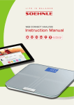
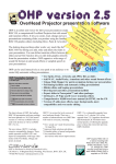
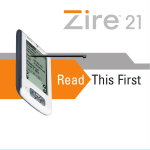
9/21/01
12:58 AM
Page 1
1
MA
TE
RI
AL
Chapter
PY
RI
GH
TE
D
Read Me First
CO
2960c01.qxd
2960c01.qxd
9/21/01
2
12:58 AM
Page 2
CHAPTER 1 • Read Me First
I
f you’ve ever installed a computer program, you’ve probably seen one or more little paper
slips saying “Read me first” or “No, read me first,” which contain details you should know
before installing the program, such as “If you do not have a Ph.D. in computer science,
please acquire one before proceeding.” Many programs also place text files onto your hard drive
with names like README.1ST and NOREADME.1ST to provide similarly vital information that you
are likely to read for the first time two years later.
Well, this is your “Read Me First” chapter, and we even went to the expense of binding it
with the rest of the book. This chapter contains information you’re likely to need in several of the
following chapters. Before you launch into this book’s detailed procedures, take a look here for a
few tips on tools, PC cover removal, and PC anatomy. Even those of you who’ve already performed one or more PC surgeries may enjoy a quick review, and for those of you who wouldn’t
know a motherboard from a cheese board, this chapter is de rigueur.
As I describe specific procedures in the chapters that follow, I’ll describe (and include
pictures of) any specific hardware relevant to the procedure. This chapter will simply serve to
suggest some appropriate tools, lay down some basic ground rules for handling electronic
devices, and help you get your bearings when you dive under your computer’s cover for the
first time.
Tools for Upgraders
Whether you’re working on cars, fission reactors, or PCs, having the right tools makes all the difference. Don’t attempt any of the procedures in this book if you don’t have the tools I mention at
the start of each procedure. You’ll end up stripping screws, scratching circuit boards, and generally upgrading your PC right into the trash can.
Thankfully, the tools you’ll need for the jobs I describe in this book are mostly common
household ones: screwdrivers, flashlights, sledge hammers, etc. However, most of you won’t have
a dental mirror or Torx screwdriver in your collection, so picking up a few specialized items like
these can make the difference between fun and frustration.
TIP I have yet to see a “PC toolkit” that has all the items on my list or that doesn’t
include at least a couple of tools that you’ll never need. Also, tools that come in
kits marketed for computer use tend to bend, break, or corrode after about five
minutes of use. My advice is to get the individual tools from your local hardware
store and make your own kit.
2960c01.qxd
9/21/01
12:58 AM
Page 3
Tools for Upgraders
The following descriptive list should help you fill out your PC upgrade toolkit. I’ll start with
the common items and work my way toward the more obscure ones.
• Screwdrivers are the most common tools you’ll use (see Figure 1.1). However, you may
need some smaller ones than those you use around the house:
• I recommend you get two or three different sizes of both slot and Phillips screwdrivers for your PC toolkit. (For the Phillips-head screwdrivers, get sizes 0, 1, and 2.)
• If you have a Compaq PC, you’ll also need a set of Torx screwdrivers, which you can
buy either at a PC store or at an auto parts dealer (Torx screwdrivers are used for
adjusting American car headlights.) Sizes T-10 and T-15 are the ones you’re likely
to need.
• Finally, you may want to have a set of jeweler’s screwdrivers on hand, especially if
you plan on working on your notebook computer. Like everything else on portable
PCs, the screws are smaller than usual.
Slot
Phillips
Torx
Jeweler’s
Figure 1.1 Screwdrivers
WARNING Many screwdrivers nowadays come magnetized for ease of retrieving lost
screws. Make sure you never work on a PC with a magnetic screwdriver. When in
doubt, test the tool on a small screw.
3
2960c01.qxd
4
9/21/01
12:58 AM
Page 4
CHAPTER 1 • Read Me First
• A nut driver—the quarter-inch variety—is the only one you need. This tool is nothing
more than a socket wrench without the wrench. You can sometimes use a nut driver to
remove a screw that you can’t get a good grip on with a screwdriver, for example because
the slot has been stripped.
• Flashlights (see Figure 1.2) are a big help, especially with today’s cram-everything-intothe-smallest-possible-space home PCs. I like to have two kinds on hand: the big square
kind with a handle that use the US$10 lantern batteries are great for placing over the
work area, and the little flexible-arm pinpoint kind are great for shedding light into tight
corners. (You can also hold the small kind in your teeth if you have to.)
• Needle-nose pliers (see Figure 1.3) come in handy for fishing loose screws out of tight
spots and for straightening bent connector pins.
• Wire cutters (also in Figure 1.3) aren’t often necessary for cutting wires, but they are
useful for cutting the annoying ties that sometimes come with a new device’s packaging.
• Electrical tape isn’t really a tool, but it should be in your PC toolkit because it’s great
for patching friction-worn areas on gray ribbon cables and for covering up connectors
you want to make sure you don’t use.
Flexible
Figure 1.2 Flashlights
Lantern
2960c01.qxd
9/21/01
12:58 AM
Page 5
Tools for Upgraders
Wire cutters
Needle-nose pliers
Figure 1.3 Pliers and cutters
• Wire ties also aren’t really tools, but they are wonderfully useful both inside and outside
the PC’s enclosure. These plastic ribbons have one pointy, ribbed end that fits into a
hole in the other end; when you snug up the loop, it stays tight.
• A jar lid or small paper cup is great for holding screws.
• A dental mirror is handy for situations when you need a circuit board model number
or chip label or other printed information, and the component is situated exactly wrong
for you to see that information.
• A retrieval tool, or spider (see Figure 1.4), is great for fishing out those tiny screws that
we all drop from time to time, especially because I advised you a few paragraphs ago to
avoid magnetic screwdrivers.
Figure 1.4 A retrieval spider
5
2960c01.qxd
6
9/21/01
12:58 AM
Page 6
CHAPTER 1 • Read Me First
Working with Electronic Devices
With a few exceptions, such as monitors, most external electronic devices, such as keyboards,
mice, and cartridge disk drives, don’t need special handling. A commitment from you not to drop
them onto a hard floor and not to spill beverages into them is usually all that’s needed. Even
devices that we traditionally think of as fragile, such as cameras, are really very rugged. (I
dropped my digital camera more than once during the course of taking this book’s photographs,
and it didn’t miss a pixel.)
When you start working with internal electronic devices, however, the rules change. Circuit
boards, memory modules, processors, and the like require different handling precautions. Here
they are in brief:
• Don’t touch the shiny parts, especially the metallic connectors on the edge of a circuit card. The oil on your fingers leaves a corrosive residue that can interfere with good
clean connections.
• Handle devices by their edges, preferably the edges that don’t have metallic connectors.
• Don’t stack circuit boards. They can scratch each other.
• Watch out for static. Even the pros have a tough time with static electricity. (I still
remember the motherboard roundup in a popular PC magazine, in which the reviewers
fried nearly half of the units they were supposed to test by inadvertently touching them
when their bodies had built up a static charge.) Try not to work on carpeted floors (if you
have to, then work barefoot); don’t work in a wool sweater; wear an antistatic wrist strap;
frequently ground yourself by touching the PC’s metallic chassis or power supply box;
humidify the work area; keep components in their antistatic bags until you’re ready to
install them; and try to get the job done in one sitting, so you don’t have to get up and
walk someplace and then sit back down, having built up a big static charge.
• Doff your jewelry. Remove your rings, wristwatches, bracelets, necklaces, and so
forth; they can scratch circuit boards and also get caught in tight places. (You can leave
toe, nose, and navel rings in place, unless you plan on doing things with your PC that I
don’t want to hear about.)
• Don’t force a fit. Whether you’re inserting a circuit board or connecting a plug into a
socket, line the devices up first, and then make your connection. Pay attention to any
keys (raised plastic areas) that ensure you can only connect something one way. Ribbon
cables often have one end wire painted red or black; that end should match up with the
“pin 1” designation on the circuit board connector.
2960c01.qxd
9/21/01
12:58 AM
Page 7
Opening a PC’s Cover
• Remove with care. When disconnecting a device, if reasonable force won’t release it,
look for a plug, latch, or lock that you may need to press/twist/release. When removing a
circuit board from a slot, rock it from side to side along its length while pulling up, and
don’t grab the chips to get leverage.
• Keep things clean. Dust is the enemy of electronics. It interferes with connections
and traps heat. Wipe or blow dust away from the components you plan to work on
before you start work. (You don’t need a can of compressed air; just inhale deeply, shut
your eyes, and blow.) Wash your hands. Wipe the table clean.
• Always power down. Don’t ever connect the PC to AC power when the cover is off.
Opening a PC’s Cover
When I started working with computers a couple of decades ago, opening the cover was very
simple. You looked at the back of the PC, located the five screws that held the cover on, removed
them, and slid the cover forward and off. Today, we have PC covers held in place by screws,
knobs, snaps, and tabs; some designs are more complex than Victorian-era undergarments. However, the general technique for getting inside a PC hasn’t changed greatly. Here are the usual
steps for removing a PC’s cover.
TIP If you have your computer’s user manual, it will contain a description that is
both more detailed and more model-specific than what follows.
1. Turn the computer off.
2. Disconnect everything from the PC’s back panel: keyboard and mouse connectors,
video connector, power cord, modem cable, network cable, and so forth (see Figures 1.5
and 1.6).
3. Locate the cover screws. These are usually Phillips-head screws at the back of the PC.
Be careful, though: the screws that hold the cover on look a lot like the screws that hold
the power supply in place. The power supply screws are typically a bit more “interior”
than the cover screws, which live on the perimeter (see Figure 1.7).
TIP Some PCs don’t have cover screws; instead, they have tabs or latches holding
the cover in place. Still other designs use knurled knobs instead of screws or
latches.
7
2960c01.qxd
8
9/21/01
12:58 AM
Page 8
CHAPTER 1 • Read Me First
Keyboard cable
Mouse cable
USB cable
Power cable
Parallel printer cable
Speaker cable
Modem cable
Video cable
Figure 1.5 A PC’s back panel, dressed
4. Remove the cover screws. Place them somewhere convenient where they won’t roll
away, such as an inverted jar lid.
5. Undo any latches that may secure the cover in place even with the screws off. Figure 1.8
shows two different types of latches that you may see. You may also have to unlock a
cover lock, especially if your computer is a “business” model.
6. Slide the cover most of the way off (see Figure 1.9). The way most PCs work, you slide
the cover about 80 or 90 percent of the way off, and the cover stops sliding. (If you have
a PC where the cover just slides all the way off, you can skip step 7.)
2960c01.qxd
9/21/01
12:58 AM
Page 9
Opening a PC’s Cover
Keyboard port
USB port
Mouse port
(PS/2 style)
Power jack
Parallel printer port
Speaker port
Modem port
(RJ-11 style)
Video port
(DB15 style)
Figure 1.6 A PC’s back panel, undressed
7. Lift the cover straight up and completely off (see Figure 1.10). You may need to pull the
sheet metal apart just a little at the bottom in order to clear the chassis. Do this operation
slowly so you don’t bang any internal circuit boards or cables with the edge of the cover.
Reassembly is the reverse of disassembly, but here are two tips. First, be very careful when
sliding that cover back into place, so that you don’t catch and tear any floating ribbon cables.
Figure 1.11 shows a PC (admittedly, not the greatest design) in which the cover has damaged an
exposed disk drive controller cable. A bit of electrical tape can mend a small abrasion, but if you
notice severed wires, a new cable is in order.
Second, take care that you’ve placed the bottom edges of the cover right where they need to
be before you slide it into place. Many covers use a sort of tongue-and-groove construction, and
the tongue of the PC’s sheet metal needs to fit into the groove of the cover’s edge in order to get
a good tight fit. Clues that the cover is misaligned: one edge looks tighter than the other, or the
cover screws don’t seem to fit right. Take the cover off and try it again.
9
2960c01.qxd
10
9/21/01
12:59 AM
Page 10
CHAPTER 1 • Read Me First
Cover screw
Power supply screws
Cover screw
Cover screw
Figure 1.7 Cover screws versus power supply screws.
Cover
latch
Cover
latch
Figure 1.8 Cover latches.
2960c01.qxd
9/21/01
12:59 AM
Page 11
Opening a PC’s Cover
Figure 1.9 Sliding a cover most of the way off
Figure 1.10 Lifting a cover all the way off
11
2960c01.qxd
12
9/21/01
12:59 AM
Page 12
CHAPTER 1 • Read Me First
Figure 1.11 Cable damage from cover removal
Gross Internal Anatomy
The interior of a PC can vary quite a bit from one unit to the next, but all PCs contain the following major components:
• Motherboard (a.k.a. system board), hosting the CPU, memory, and various other integrated circuits
• Expansion slots (usually all you see are PCI slots nowadays—they’re short and beige—
but your PC may also have one or more ISA slots, which are longer and black, for older
hardware)
• Adapters (add-on boards that fit into the expansion slots)
• Power supply (usually a silver-colored metal box with a yellow label)
• Internal disk drives (including usually one diskette drive, one or more hard drives, a
CD-ROM drive, and sometimes a Zip drive)
• Power cables (groups of brightly colored wires ending in white connectors that plug
into internal disk drives)
2960c01.qxd
9/21/01
12:59 AM
Page 13
Gross Internal Anatomy
• Signal cables (typically, flat gray ribbon cables that carry data between the motherboard or adapters and internal disk drives)
Rather than describe these components in detail, Figures 1.12 and 1.13 show two fairly typical PC designs, the mini-tower and the tower, with labels for most of the major internal organs.
Again, the documentation for your particular computer is likely to have a more relevant and
detailed photo or drawing, so you should use that if you have it. (If you have a notebook computer, you’re really going to have to depend on the manufacturer’s documentation, because the
interior layouts of these portable units vary even more than those of non-portable PCs.)
CPU
Motherboard
Power cables
Internal
disk drives
Power supply
Memory
Adapters
Figure 1.12 Inside a typical mini-tower PC
Expansion
slots
Signal
cables
13
2960c01.qxd
14
9/21/01
12:59 AM
Page 14
CHAPTER 1 • Read Me First
Power supply
Power cables
Internal
disk drives
Memory
CPU
Signal cables
Motherboard
Adapters
Expansion
slots
Figure 1.13 Inside a typical tower PC