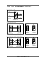
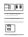
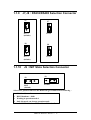
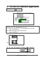
1
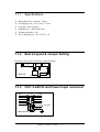
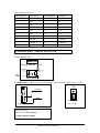
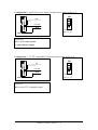
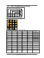
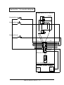
MMICON
Hardware Manual
ICP DAS
Industrial Computer Products
Data Acquisition System
MMICON Hardware Manual ---- 1
Warranty
All products manufactured by ICP DAS are warranted against defective materials
for a period of one year from the date of delivery to the original purchaser.
Warning
ICP DAS assume no liability for damages consequent to the use of this product. ICP
DAS reserves the right to change this manual at any time without notice. The information
furnished by ICP DAS is believed to be accurate and reliable. However, no
responsibility is assumed by ICP DAS for its use, nor for any infringements of patents or
other rights of third parties resulting from its use.
Copyright
Copyright 1997 by ICP DAS. All rights are reserved.
Trademark
The names used for identification only maybe registered trademarks of their
respective companies.
MMICON Hardware Manual ---- 2
Table of contents
1.
INTRODUCTION.....................................................................................................................................4
1.1.1 Specifications ...............................................................................................................................6
1.1.2 Board Layout & Jumper Setting................................................................................................6
1.1.3 CN1: 5-24V DI and Power Input connector.............................................................................6
1.1.4 CN2 : 4*4 KBD input connector................................................................................................9
1.1.5 CN3 : RS232/RS485 connector................................................................................................10
1.1.6 VR1 : LCD Brightness Adjustment ..........................................................................................11
1.1.7 JP1 : VCOM Selection Connector ...........................................................................................11
1.1.8 J5,J6 : Frame Ground Selection Connector..........................................................................12
1.1.9 J7,J8 : RS232/RS485 Selection Connector............................................................................13
1.1.10 J9 : INIT State Selection Connector......................................................................................13
2.
5V-24V I/O INTERFACE APPLICATION........................................................................................14
2.1 DIO CONNECTION 1 : 24V NON-ISOLATED ...........................................................................................15
2.2
DIO CONNECTION 2 : 24V NON-ISOLATED ..........................................................................................16
2.3
DIO CONNECTION 3 : 24V ISOLATED ..................................................................................................17
2.4
DIO CONNECTION 4 : 5V ISOLATED ....................................................................................................18
3. PC RS232 INTERFACE APPLICATION .............................................................................................19
4. PLC RS232 INTERFACE APPLICATION .........................................................................................21
5. PC RS485 INTERFACE APPLICATION ............................................................................................23
MMICON Hardware Manual ---- 3
1.
Introduction
The MMICON is a compact size man-machine interface control board with a 4*4
keyboard interface , a 240*64 dots graphics LCD interface ,a RS-232C or RS-485
interface , 10 isolated digital input. This control board is designed to work with PC or
PLC to implement a cost-effective man machine interface.
PC based user can use it to integrate a operator interface , instead of the regular
monitor and keyboard. The MMICON has RS-232C or RS-485 ( jumper selectable ) port
to communicate with PC. The PC can send out command to change the display page or
send out the string to display on the specified location. The user should need a ND-6520
(RS-232C/RS-485 converter) to implement a RS-485 network .The PC can control up to
256 MMICON controllers in one 2-wire RS-485 network.
PLC user can use digital I/O port to communicate with the MMI-CON. The PLC send
the page number through digital I/O and the MMI-CON will automatically display the
related image stored in EEPROM.
When the user use OMRON PLC ,he can use RS-232C to communicate with MMICON port. The PLC send the page number into the PLC internal data memory (DM). The
MMI-CON polls the data memory all the time and displays the value of the internal data
memory. The DM value can be mixed with the image stored in EEPROM . The input
value of the 4*4 KBD can be written into the data memory. Therefore it is also suitable
as a man machine interface for PLC.
The user can edit the text and paint the Images using the utility in PC environment .
The hex file can be programmed into the EEPROM by regular programmer.
The MMICON is a low cost man machine interface controller. The
Starter-Kit
MMICON
is designed to demonstrate the function of MMICON. The Starter-Kit
gives three demonstrations as following:
demo 1 : 5-24V digital I/O interface(for uP, PC or PLC I/O)
(240*64 LCD*256 pages)
demo 2 : PC RS232 interface
(240*64 LCD*256 pages+4x4 KBD + Function_Key*8)
demo 3 : Omron PLC RS232 interface (others soon)
(240*64 LCD*256 pages+4x4 KBD + Function_Key*8)
MMICON Hardware Manual ---- 4
The MMICON can be applied to various application as following:
Application 1 : 5-24V digital I/O interface(for uP, PC, PLC I/O)(refer to Chap. 2)
Application 2 : PC RS232 interface à refer to Chap. 3
Application 3 : PLC RS232 interface à refer to Chap. 4
Application 4 : PC RS485 inteface à refer to Chap. 5
Application 1 à select MMICON mode 0 à initial mode(with JP2 in INIT
position)
Application 2 à select MMICON mode 1/2 à (with JP2 in normal position)
Application 3 à select MMICON mode 1 à (with JP2 in normal position)
Application 4 à select MMICON mode 3 à (with JP2 in normal position)
Mode 0 : initial mode à with JP2 in INIT position
ƒ Suitable for application 1
ƒ Module address = 00
ƒ Only in this mode can change to other mode
Mode 1 : PC RS232/RS485 mode à with JP2 in normal position
ƒ Module address stored in MMICON internal eeprom (not LCD image EPROM)
ƒ Suitable for application 2 : PC RS232 interface(J7 in 1-2, J8 in 1-2)
ƒ Suitable for application 4 : PC RS485 interface(J7 in 2-3, J8 in 2-3)
ƒ KBD input will be stored in buffer until PC read
Mode 2 : PC RS232 mode à with JP2 in normal position
ƒModule address stored in MMICON internal eeprom (not LCD image EPROM)
ƒ Suitable for application 2 : PC RS232 interface(J7 in 1-2, and J8 in 1-2)
ƒKBD input will return to PC immediately.
Mode 3: PLC RS232 mode à with JP2 in normal position
ƒSuitable for application 3 : PLC RS232 interface(J7 in 1-2 and J8 in 1-2)
Factory Setting :
(1) : JP2 in INIT position à mode 0
(2) : J7 in 1-2, J8 in 1-2
(3) : (if move JP2 to normal position à Mode 3)
Refer to “MMIDOS Software User Manual” for how to change operation mode.
MMICON Hardware Manual ---- 5
1.1.1
ƒ
ƒ
ƒ
ƒ
ƒ
ƒ
Specifications
Board dimension : 162 mm * 70 mm
LCD display area : 107.97 mm * 77 mm
LCD dots : 240 * 64 dots
EPROM size : 128K/256K/512K
DI input impedance : 3K
Power Requirement : 10V-30V DC, 1A
1.1.2
Board Layout & Jumper Setting
Board layout is given as following: (default setting)
CN1
VR1
CN2
JP1
J5
CN3
J6
J8
J7
MMICON
J9
Iinit state
1.1.3
DI1
DI3
DI5
DI7
DI9
Ext V
normal
CN1: 5-24V DI and Power Input connector
1
2
DI2
DI4
DI6
DI8
DI10
Ext Power +10~30V
Ext Gnd
MMICON CN1
20
MMICON Hardware Manual ---- 6
Pin Assignment of CN1.
Pin Assignment Description
Pin Assignment Description
1
DI 1
2
DI 2
3
DI 3
4
DI 4
5
DI 5
6
DI 6
7
DI 7
8
DI 8
9
DI 9
10
DI 10
11
Ext V
12
Ext V
13
Ext Gnd
14
Ext Power
15
Ext Gnd
16
Ext Power
17
Ext Gnd
18
Ext Power
19
Ext Gnd
20
Ext Power
External Power : can be 10V to 30V
Block diagram of DI :
MMICON
Digital input diagram
+5V
Vcom
DI(x)
Photo couple
Configuration 1 : single 10V-30V power supply (non-isolation ) (Refer Sec. 2.1/2.2)
JP1
1
+10~30V
GND
Vcom form
pin_13_20
MMICON CN1
Vcom=10V-30V
DI(x) can be relay contact
or open collector output
MMICON Hardware Manual ---- 7
Configuration 2 : double 24V power supply (isolation input) (Refer to Sec. 2.3)
JP1
1
24V
+10~30V
GND
Vcom from
pin_11_12
MMICON CN1
Vcom=24V
DI(x) can be relay contact
or open collector output
Configuration 3 : 5V TTL compatible DI (isolation input) (Refer to Sec. 2.4)
JP1
1
5V
+10~30V
GND
Vcom from
pin_11_12
MMICON CN1
Vcom=5V
DI(x) can be TTL compatible signal
MMICON Hardware Manual ---- 8
1.1.4
CN2 : 4*4 KBD input connector
D3
D2
Key switch
D1
9
D0
A3
8
A2
A1
5
4
3
7
6
2
1
A0
MMICON CN2
4*4 KBD definition in mode 3 (PLC-RS232)
4*4 KBD return code in mode 1/2/3 (PC-RS232/RS485)
KEY-CODE KEY NAME KEY-CODE KEY NAME KEY-CODE KEY NAME
0x01
0x02
0x03
0x04
0x05
0x06
0x07
0x08
0x09
0x0A
0x0B
0x0C
0x0D
0x0E
0x0F
0
.
Enter
1
2
3
+
4
5
6
7
8
9
Back
Space
0x11
0x12
0x13
0x14
0x15
0x16
0x17
0x18
0x19
0x1A
0x1B
0x1C
0x1D
0x1E
0x1F
ß
à
Enter
A
B
C
v
D
E
F
^
F1
F2
F3
F4
0x20
0x21
0x22
0x23
0x24
0x25
0x26
0x27
MMICON Hardware Manual ---- 9
Function-key1
Function-key2
Function-key3
Function-key4
Function-key5
Function-key6
Function-key7
Function-key8
1.1.5
CN3 : RS232/RS485 connector
Pin assignment of CN3 :
D+
1
6
2
7
3
D-
RXD
TXD
8
4
9
5
RS-485
GND
RS-232
MMICON CN3
RS232 connection for PC
J7
1
2
3
4
6
6
7
7
8
8
9
9
5
1
2
3
4
5
MMICON CN3
J8
RS232
(default)
RS232
(default)
PC RS-232
RS232 connection for PLC(Omron CQM1)
J7
1
2
3
4
6
6
7
7
8
8
9
9
5
MMICON CN3
J8
1
2
3
4
5
RS232
(default)
OMRON RS-232
MMICON Hardware Manual ---- 10
RS232
(default)
RS485 connection.
J7
D+
1
2
3
D-
4
J8
6
7
8
9
RS485
5
RS-485
RS485
RS-485
MMICON CN3
1.1.6
VR1 : LCD Brightness Adjustment
Turn VR1 can change the brightness of LCD display.
1.1.7
JP1 : Vcom Selection Connector
Vcom is the common source of MMICON DI. The Vcom can be come from pin_11_12 of
CN1 of from pin 13-20 of CN1. There are various DIO connections introduced in Chapter
2 which will select the different Vcom configuration. Refer to Chapter 2 for details.
Block diagram of MMICON DI :
MMICON
Digital input diagram
+5V
Vcom
DI(x)
Photo couple
MMICON Hardware Manual ---- 11
Pin assignment of CN1.
DI1
DI3
DI5
DI7
DI9
Ext V
1
2
DI2
DI4
DI6
DI8
DI10
Ext Power +10~30V
Ext Gnd
MMICON CN1
20
Vcom : can be from pin_11_12 or pin_13_20
JP1
JP1
Vcom from
pin_11_12
Vcom from
pin_13_20
(default)
1.1.8
J5,J6 : Frame Ground Selection Connector
J5 : enable/disable the frame ground of CN2 connecting to GND of MMICON
J6 : enable/disable the frame ground of CN3 connecting to GND of MMICON
J5
disable
(default)
J5
enable
J6
disable
(default)
J6
enable
MMICON Hardware Manual ---- 12
1.1.9
J7,J8 : RS232/RS485 Selection Connector
J7
J7
RS232
(default)
RS485
J8
J8
RS232
(default)
1.1.10
RS485
J9 : INIT State Selection Connector
J9
J9
INIT
(default)
normal
Select INIT position will force the MMICON go to initial state as following :
1. Module address=00
2. RS232 baudrate = 9600
3. Working in operation mode 0
4. Only this mode can change operation mode.
Refer to “MMIDOS Software User Manual” for details.
MMICON Hardware Manual ---- 13
2. 5V-24V I/O Interface Application
J9 must select INIT position.
MMICON to uP, PC or PLC via digital I/O
PLC
Isolation
digital
input
(without RS-232C)
uP à use 5V TTL compatible DO (Sec. 2.4)
PC based IO cards à use 5V TTL compatible DO or 24V DO
(Sec. 2.1/2.2/2.3/2.4)
PLC à use 24V relay or open collector DO
(Sec. 2.1/2.2/2.3)
MMICON DI Block diagram :
MMICON
Digital input diagram
+5V
Vcom
DI(x)
Photo couple
uP, PC, PLC DO change LCD page control diagram:
DO1 to DO 8 à PAGE (0-255 )
DO 9 à trigger
MMICON Hardware Manual ---- 14
2.1 DIO Connection 1 : 24V non-Isolated
Single external power supply+PLC_relay_output+non-isolated-connection
PLC (with relay output)
MMICON(with default setting)
Vcom
Relay(DO1,page)
Relay(DO2,page)
Relay (DO9,trigger)
DO1-DO8=Page
DO9=Trigger
DI1
DI3
DI5
DI7
DI9
Ext V
1
2
DI2
DI4
DI6
DI8
DI10
Ext Power +10~30V
Ext Gnd
+24V
input
GND
input
MMICON CN1
20
JP1
External Power Supply
+24V
output
Select Vcom = pin_13_20
GND
output
MMICON Hardware Manual ---- 15
2.2 DIO Connection 2 : 24V non-Isolated
Single external power supply+PLC_O.C._output+non-isolated-connection
PLC (with O.C. output)
MMICON(with default setting)
Vcom
Open Collector(DO1)
Open Collector(DO2)
Open Collector (DO9,Trigger)
DO1-DO8=page
DO9=Trigger
DI1
DI3
DI5
DI7
DI9
Ext V
1
2
DI2
DI4
DI6
DI8
DI10
Ext Power +10~30V
Ext Gnd
+24V
input
GND
input
MMICON CN1
20
JP1
External Power Supply
+24V
output
Select Vcom = pin_13_20
GND
output
MMICON Hardware Manual ---- 16
2.3
DIO Connection 3 : 24V Isolated
Double external power supply+PLC_relay_output + isolated-connection
PLC (with relay output)
MMICON(with JP1 changed)
Vcom
Relay(DO1)
Relay(DO2)
Relay (DO9,trigger)
DO1-DO8=page
DO9=Trigger
DI1
DI3
DI5
DI7
DI9
Ext V
1
2
DI2
DI4
DI6
DI8
DI10
Ext Power +10~30V
Ext Gnd
+24V
input
GND
input
MMICON CN1
External Power Supply
1+24V
GND
output
20
JP1
Select Vcom = pin_11_12
output
External Power Supply
2+24V
GND
output
MMICON Hardware Manual ---- 17
output
2.4
DIO Connection 4 : 5V Isolated
Single external power supply+PC_TTL_output + isolated-connection
PC(with TTL output)
MMICON(with JP1 changed)
Vcom
TTL (DO1)
TTL (DO2)
TTL (DO9,trigger)
DO1-DO8=page
DO9=Trigger
+5V
outputt
DI1
DI3
DI5
DI7
DI9
Ext V
1
2
DI2
DI4
DI6
DI8
DI10
Ext Power +10~30V
Ext Gnd
GND
output
MMICON CN1
20
JP1
Select Vcom = pin_11_12
External Power Supply
+24V
output
MMICON Hardware Manual ---- 18
GND
output
3.
PC RS232 Interface Application
J9 must select normal position.
Function-Key * 8
MMICON to PC via RS-232C
RS-232C
PC
Instead of the
regular monitor
and keyboard
4x4 KBD
RS232 connection.
J7
1
2
3
4
6
6
7
7
8
8
9
9
1
2
3
4
5
RS232
(default)
5
MMICON CN3
PC RS-232
4*4 KBD connection
D3
D2
D1
9
D0
A3
8
A2
A1
5
4
3
7
6
2
1
A0
Key switch
J8
MMICON CN2
Dx
Push botton
Ax
MMICON Hardware Manual ---- 19
RS232
(default)
Function Key * 8 connection diagram.
MMICON(with JP1 changed)
Vcom
Function Key 1
Function Key 2
Function Key 8
DI1
DI3
DI5
DI7
DI9
Ext V
1
2
DI2
DI4
DI6
DI8
DI10
Ext Power +10~30V
Ext Gnd
MMICON CN1
20
JP1
Select Vcom = pin_11_12
External Power Supply
+24V
output
MMICON Hardware Manual ---- 20
GND
output
4.
PLC RS232 Interface Application
J9 must select normal position.
MMICON to OMRON PLC via RS-232C
RS-232C
Function_Keys * 8
OMRON
4x4 KBD
RS232 connection for PLC(Omron CQM1)
J7
1
2
3
4
6
6
7
7
8
8
9
9
1
2
3
4
5
RS232
(default)
5
MMICON CN3
OMRON RS-232
4*4 KBD connection
D3
D2
D1
9
D0
A3
8
A2
A1
5
4
3
7
6
2
1
A0
Key switch
J8
MMICON CN2
Dx
Push botton
Ax
MMICON Hardware Manual ---- 21
RS232
(default)
Function Key * 8 connection diagram.
MMICON(with JP1 changed)
Vcom
Function Key 1
Function Key 2
Function Key 8
DI1
DI3
DI5
DI7
DI9
Ext V
1
2
DI2
DI4
DI6
DI8
DI10
Ext Power +10~30V
Ext Gnd
MMICON CN1
20
JP1
Select Vcom = pin_11_12
External Power Supply
+24V
output
MMICON Hardware Manual ---- 22
GND
output
5.
PC RS485 Interface Application
J9 must select normal position.
MMICON to PC via RS-485 Network
RS-232C
RS-485
ND-6520
RS
232C/485
ND-6000
series
A/D,D/A,
D/I/O
PC
Function_Keys * 8
MMICON-2
4x4 KBD
Function_Keys * 8
4x4 KBD
MMICON-3
Function_Keys * 8
4x4 KBD
Function_Keys * 8
MMICON-255
MMICON Hardware Manual ---- 23
MMICON-1
RS485 connection.
J7
D+
1
2
3
D-
4
6
7
8
9
RS485
5
RS-485
RS-485
MMICON CN3
4*4 KBD connection
D3
D2
D1
9
D0
A3
8
A2
A1
5
4
3
7
6
2
1
A0
Key switch
J8
MMICON CN2
Dx
Push botton
Ax
MMICON Hardware Manual ---- 24
RS485
Function Key * 8 connection diagram.
MMICON(with JP1 changed)
Vcom
Function Key 1
Function Key 2
Function Key 8
DI1
DI3
DI5
DI7
DI9
Ext V
1
2
DI2
DI4
DI6
DI8
DI10
Ext Power +10~30V
Ext Gnd
MMICON CN1
20
JP1
Select Vcom = pin_11_12
External Power Supply
+24V
output
MMICON Hardware Manual ---- 25
GND
output