1
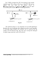
7000 Bus Converter
User Manual
For 7520, 7520R, 7520A, 7510A, ISA-7520
7000 New Features
1. Self Tuner Inside
2. Multiple Baud Rate
3. Multiple Data Format
4. Dual WatchDog Inside
5. True Distributed Control
6. High Speed&High
Density I/O
Your Powerful Tools
Create New Ideas
Create New Applications
Warranty
All products manufactured by ICP DAS are warranted against
defective materials for a period of one year from the date of delivery to
the original purchaser.
Warning
ICP DAS assume no liability for damages consequent to the use of
this product. ICP DAS reserves the right to change this manual at any
time without notice. The information furnished by ICP DAS is believed
to be accurate and reliable. However, no responsibility is assumed by
ICP DAS for its use, nor for any infringements of patents or other
rights of third parties resulting from its use.
Copyright
Copyright 1997 by ICP DAS. All rights are reserved.
Trademark
The names used for identification only maybe registered
trademarks of their respective companies.
Patent pending
7000 Bus Converter User Manual (version 1.0) -------- 1
Table of Contents
1.
2.
3.
4.
5.
Introduction ...........................................................................................................................3
1.1 7000 Overview ..............................................................................................................3
1.2 7000 Related Documentation ........................................................................................4
1.3 7000 Common Features ...............................................................................................5
1.4 7000 System Network Configuration............................................................................6
1.5 7000 Dimension ..........................................................................................................11
7520 / 7520R/7520A/ISA-7520R.........................................................................................14
2.1 Pin Assignment ...........................................................................................................14
2.2 Specifications ..............................................................................................................15
2.3 Block Diagram ............................................................................................................17
2.4 Basic Wire Connection................................................................................................18
2.5 How to Select 7520/7520R .........................................................................................19
7510/7510A.........................................................................................................................23
3.1 Pin Assignment ...........................................................................................................23
3.2 Specifications ..............................................................................................................24
3.2 Block Diagram ............................................................................................................25
3.3 Basic Wire Connection................................................................................................26
7000 RS-485 Networking.....................................................................................................27
4.1 Standard/Isolation Configuration ................................................................................27
4.2 PLC Networking Application......................................................................................31
4.3 PC Networking Application ........................................................................................32
4.4 RS-232 Devices Network............................................................................................33
7000 Quick Start..................................................................................................................34
5.1 Find Status of Unknown Module ................................................................................34
5.2 Change Module Address .............................................................................................37
5.3 Change Baud Rate.......................................................................................................38
5.4 Checksum Enable/Disable...........................................................................................41
5.5 QBASIC Demo Program.............................................................................................44
Patent pending
7000 Bus Converter User Manual (version 1.0) -------- 2
1.
Introduction
The 7000 are a family of remote controllable data
acquisition modules. They provide A/D, D/A, DI/O,
Timer/Counter, MMI and other functions. These modules can
be remote controlled by a set of commands.
1.1
7000 Overview
7000 can be divided into several groups based on their function as
following:
group 1 : bus converter modules, support bus converter & repeater
7520/7520R/ISA-7520R : RS-232 to RS-485 converter,
3000V isolation
7510 : RS-485 to RS-485 repeater, 3000V isolation
7520A : RS-232 to RS485&RS-422 converter, 3000V
isolation
7510A : RS-485 and RS-422 repeater, 3000V isolation
group 2 : DIO modules, support TTL, isolated DIO, relay & O. C.
output
7050 : TTL IO, 7*In, 8*Out
7052 : isolated DI, 8*In
7053 : Non-isolated DI, 16*In
7060 : isolated DI & relay output, 4*In+4*Relay
7041 : isolated DI, 14*In
7042 : isolated O. C. DO, 13*Out
7044 : high driver O.C. output I + isolated DI, 4*In+8*Out
7067 : relay output, 7*Relay
group 3 : DA module, support voltage/current output : 7021
group 4 : AD modules, support voltage/current/thermocouple/RTD
measurement
7011/7011D : single-channel thermocouple measurement
7012/7012D : single-channel large signal measurement
7013/7013D : RTD measurement
7014D : general analog signal measurement with LEDs display
7017 : multi-channel 7012
7018 : multi-channel 7011
Patent pending
7000 Bus Converter User Manual (version 1.0) -------- 3
group 5 : Timer/Counter modules : 7080, 7080D
group 6 : Man Machine Interface : MMICON=240*64 LCD+4*4
KBDs+8*function_key
group 7 : Power relay Modules :
RM104/108/116 : 4/8/16 channels of form-C, SPST, 400V AC, 16A
RM204/208/216 : 4/8/16 channels of form-C, SPDT, 400V AC, 5A
group 8 : Embedded Processor module
7188=188+Ram+Flash-Rom+more features
group 9 : wireless modem module : SST-288
group 10 : Power supply module
ACE-540A : 24V/2A power supply
DIN-540A : ACE-540A with DIN-RAIL mount
PWR-24/220V : 220V AC input, 24V/0.1A output power adapter
PWR-24/110V : 110V AC input, 24V/0.1A output power adapter
Over 10 modules are under development
ODM modules call for details.
1.2 7000 Related Documentation
• NAP7000S User Manual : for software NAP7000S, utility program
source
• NAP7000P User Manual : for software NAP7000P, DLL driver for 7000
• NAP7000D User Manual : for software NAP7000D, DDE driver for 7000
• NAP7000L User Manual : for software NAP7000O, OLE driver for 7000
• 7000 Bus Converter User Manual : for
7510/7520/7520R/7520A/7510A
• 7000 DIO User Manual : for 7050/7052/7053/7060/7041/7042/7044/7067
• 7000 A/D Group1 User Manual : for 7017/7018/7013/7013D
• 7000 A/D Group2 User Manual : for 7011/7011D/7012/7012D/7014D
• 7000 D/A User Manual : for 7021
• 7000 Timer/Counter User Manual : for 7080D
• 7000 Embedded Controller User Manual : for 7188
• MMICON Hardware Manual : for MMICON
• MMIDOS User Manual : for MMICON software
• Application Note : EM001 ! for MMICON evaluation
Patent pending
7000 Bus Converter User Manual (version 1.0) -------- 4
1.3
7000 Common Features
Isolation voltage : 3000 Vdc
Communication :
• Asynchronous half-duplex 2-wire RS-485 network
• Max. distance without repeater=4000 feet (1.2Km)
• Speed=1200,2400,4800,9600,19200,38400,57600,115200
• Connecting 256 modules in one RS-485 bus without repeater
• Multiple baud rate and multiple data format can share the same RS485 bus(7520/7510)
• Different baud rate and the same module address can share the same
RS-485 bus
• Connecting 256*8=2048 modules max. in one RS-485 bus with
repeater.
• 7000 series data format=1 start + 8 data + 1 stop + no parity = 10-bit
• Two extra checksum bytes can be enable/disable
• Built-in transient voltage suppresser and PTC protector
• Sharing the same RS-485 bus with the RS-485 or RS-232 device
which communicates in multiple data format(not 10-bit) and
multiple baud rate. (Use 7520 to convert RS-232 to RS-485)
Power :
• +10V ~ +30V DC
• Power reverse protection, Over-voltage brown-out protection
System :
• Dual watchdog inside, power-on start value and safe value for host
failure
• Operating temperature : -10 to 70ºC (14 to 185ºF)
• Storage temperature : -25 to 80ºC (-13 to 185ºF)
•
Humility : 5 to 95%, non-condensing
Patent pending
7000 Bus Converter User Manual (version 1.0) -------- 5
1.4 7000 System Network Configuration
• Multiple Baud Rate
• Multiple Data Format
➊➍7188
➋7520
➋➊COM 1
RS-232
➋➋COM 2
RS-232
➊➊7000 Series
➊➐RS-485 Network
➊➎7188
➊➏RS-485 type PLC
➊➌5860 ➊➊7000 Series
➐7510
➋➌RS-485
Network
➊➌5860
➊➑RS-485
Network
➊➊7000 Series
Baud Rate :
115200
Data : 10-bit
➊➊7000 Series
➌7520
➓Other RS-232
Devices
➑7510
Baud Rate : 19200
Data : 10-bit
➊➒RS-485 Network➎7520
➒RS-232 type
PLC
Baud Rate :
9600
➍7520
➋➊Wireless Modem
➏7520
7520 RS-232 to RS-485
converter
7510 RS-485 repeater
7000 Series:
A/D, D/A, D/I/O
modules
7188 : embedded
controller
➊➋7000 Series, baud rate= 19200, data= 10-bit
5860 : high speed ,
high channel number,
A/D, D/A, D/I/O
boards
Wireless modem
RS-232 devices : voltage
meter, current meter,
weight scale,….etc.
Amy RS-232 interface
devices.
Fig 1
Patent pending
➋➋Wireless
Modem
RS-485 Network
7000 Bus Converter User Manual (version 1.0) -------- 6
Conventional Two-Wire RS-485 Network: The conventional twowire RS-485 network use a DIP SWITCH selectable converter to
convert host RS-232 signal to two-wire RS-485 signal. The baud rate
and data format must be setted in fixed value in whole network. For
example the user can choose baud rate=9600 and data format=10 bit
per character. This limitation is inconvenient in some real world
application. The 7000 series, Adam 4000 series, Nudam 6000 series
and DATAFORTH 9B series all use 10-bit format. Some conventional
PLC use 11-bit data format and some weight scale equipment use 12bit. If the host-PC has to send command to remote module, PLC and
weight scale equipment, one possibility is to use three independent
two-wire RS-485 network. That may increase the system cost and
reduced the system reliability.
The user may use many modules in the same two-wire RS-485
network in real world applications. All these modules must
communicate in the same baud rate in the conventional system. Some
of those modules may be very close to host-PC and can communicate
with high baud rate. Some modules may be far away from the host-PC
and communicate with low baud rate. Because only one speed is
validate in the RS-485 network, the high speed modules should be
forced to communicate in low speed baud rate. The performance of the
whole system should be decreased.
7000 RS-485 Network: The 7000 RS-485 network is the most
powerful and flexible two-wire RS-485 network in the world. It is a
multiple baud rate and multiple data format network system. That is to
say, all these remote modules, PLCs, weight scale equipment
mentioned above can share the same RS-485 network. The 7520, RS232 to RS-485 converter, equips a “ Self Tuner” inside, therefore it
can detect the baud rate and data format automatically and control the
direction of RS-485 network precisely. So the user can connect all
these equipment to the same RS-485 network. This will reduce system
cost and increase reliability very much.
Patent pending
7000 Bus Converter User Manual (version 1.0) -------- 7
Operation Principle (Refer to Fig 1):
(1) The ➊Host PC send out command via the ➋➊COM1.
(2) The ➋7520 convert this RS-232 signal into ➊➐RS-485 signal.
(3) All modules connecting to ➊➐RS-485, ➊➑RS-485 and ➊➒RS-485
network will receive this command at the same time. Then all
modules will start to extract the destination address field and
compare to its local module address.
(4) The module with match address will continue to execute this host
command and the other modules will bapass this comand.
(5) After executing the host command, the destination module will send
the result back into RS-485 network. The ➊Host PC will interprete
this result and take action.
Isolated Repeater: The ➐7510 & ➑7510 are used to extend the
➊➐RS-485 to ➊➑RS-485 & ➊➒RS-485 for three conditions as
following : (1) the RS-485 path over 1.2Km or 4000 ft (2) connectting
over 256 modules in one RS-485 segment (3) break the long RS-485
path into serval short & isolated RS-485 paths for safety consideration.
Multiple Baud Rate : The modules connecting in the 7000 two-wire
RS-485 network can communicate to ➊Host PC with different baud
rate. For example, the max. speed of ➋➊Wireless Modem & ➋➋
Wireless Moden is 19200 BPS, but all 7000 series module can working
under 115200 BPS. Some conventional PLC can only communicate at
9600 max. The 7520 can auto switch the baud rate from 300 BPS to
115200 BPS. Therefore the user can connect all these device into the
same RS-485 network. The ➊Host PC will send out the different baud
rate command and only the corresponding destination module will
recognize this command and echo its result. All the other modules can
recognize this command as a invalidate command and bypass it.
Patent pending
7000 Bus Converter User Manual (version 1.0) -------- 8
Multiple Data Format: The RS-232 is a serial signal and must be
transmitted in START-bit+DATA-bit+PARITY-bit+STOP-bit. The
format of ICP CON is “ 1 START-bit+8 DATA-bit + no PARITY-bit
+ 1 STOP-bit” , totally 10 bits. But the conventional PLC use “ 1
START+7 DATA+1 PARITY+2 STOP” , totally 11 bits. The ➊Host
PC can send and receive any data format command. The devices
connecting in the 7000 two-wire RS-485 network can communicate to
➊Host PC with different data format. This feature make the user can
use one two-wire RS-485 network to connect remote modules, PLCs,
RS-232 devices and instrument in the most reliabile and low cost way.
Dual WatchDog Inside: All 7000 modules equip hardware module
watchdog and software host watchdog. The 7000 series are designed for
industry applications, therefore they can work in the harsh environment.
There are many couple noise or energy transient in such environment.
The modules may be down if these noise is really too large. The built-in
hardware module watchdog can reset the module if it is down for too
large signal. Sometimes even the host-PC may be down for hardware or
software reasons. The software host watchdog can monitor the status of
host-PC. If the host-PC is down, all the output of 7000 modules will go
to their predefined safe states for safety protection.
If the RS-485 network is open, all the host command can not send
to remote modules. This is very dangerous in real world application. The
7000 output module will force their output going to their predefined safe
state for safety consideration if the host watchdog is enable. This dual
watchdog feature will increase the system reliability very much.
True Distributed Control: The ➊➍ 7188 and ➊➎ 7188 are equiped
with a 80188, ram, flash eeprom and can download the user program.
Therefore they can handle the control details without ➊Host PC. This
is a very important feature of 7000. All the 7000 modules work in
“ SLAVE” state. They are all waiting for commands and then take
response. They can not take any action to ➊Host PC in any condition.
Therefore the user can not handle the timing critical and emergency
event by using 7000 modules. The 7188 is the best choice for this
application. The ➊➎ 7188 can work in stand alone mode after the
control program is down load.
Patent pending
7000 Bus Converter User Manual (version 1.0) -------- 9
High Speed & High Density I/O: The ➊➌5860 is a 586 PC based
controller. It can plug-in isolated D/I, D/O, A/D, D/A cards as needed.
The ➊➌5860 equips a RS-485 interface to connect to 7000 directly.
The built-in electronic ram/rom disk make it very suitable for industry
application. The full line of high density isolated cards make it very
easy to handle high channel number applications. For example, The
user can install 3 cards to get “ 32 chnnel A/D + 16 Channel D/A + 32
channel D/I + 32 channel D/O” .
7000 New Features
1. Self Tuner Inside
2. Multiple Baud Rate
3. Multiple Data Format
4. Dual WatchDog Inside
5. True Distributed Control
6. High Speed&High
Density I/O
Patent pending
Your Powerful Tools
Create New Ideas
Create New Applications
7000 Bus Converter User Manual (version 1.0) -------- 10
1.5
7000 Dimension
Fig 2
Fig 3
Patent pending
7000 Bus Converter User Manual (version 1.0) -------- 11
Fig 4
Fig 5
Patent pending
7000 Bus Converter User Manual (version 1.0) -------- 12
Fig 7
Plastic Part for Panel Mount
Patent pending
7000 Bus Converter User Manual (version 1.0) -------- 13
2. 7520 / 7520R/7520A/ISA-7520R
2.1 Pin Assignment
ISA-7520R
CN1
(for RS-232)
CN2
(for RS-485)
Fig 8
CN-1.2 connect to RS-232.2
CN-1.2 connect to RS-232.2
CN-1.2 connect to RS-232.2
CN2.1 = D+
CN2.2 = D+
CN2.6 = DCN2.7 = D-
The ISA-7520R is exactly the
same as 7520R except the ISA
interface. It is designed for
easy installation.
Patent pending
7000 Bus Converter User Manual (version 1.0) -------- 14
2.2Specifications
7520 : RS-232 to RS- 7520R : RS-232 to
RS-485 Converter
485 Converter
• Protocol : two-wire
RS-485, (D+,D-),
protocol
• Connector : plug-in
screw
terminal
block
• Speed : “ Self
Tuner”
inside,
auto
switching
baud rate, from 300
to 115200 BPS
• 256 modules max
in one RS-485
network
without
repeater
• 2048 modules max
in one RS-485
network
with
repeater
• Isolation voltage :
3000V
• Isolation site : RS232
• Repeater request :
4,000 feet or over
256 modules
• Power
requirements:+10V
to +30VDC
Power consumption :
2.2W(Max)
Patent pending
• Protocol : two-wire
RS-485, (D+,D-),
protocol
• Connector : plug-in
screw
terminal
block
• Speed : “ Self
Tuner”
inside,
auto
switching
baud rate, from 300
to 115200 BPS
• 256 modules max
in one RS-485
network
without
repeater
• 2048 modules max
in one RS-485
network
with
repeater
• Isolation voltage :
3000V
• Isolation site : RS485
• Repeater request :
4,000 feet or over
256 modules
• Power
requirements:+10V
to +30VDC
Power consumption :
2.2W(Max)
7520A : RS-232 to
RS-485 or RS-422
Converter
• Protocol : RS-485
or RS-422
• Connector : plug-in
screw
terminal
block
• Speed : “ Self
Tuner”
inside,
auto
switching
baud rate, from 300
to 115200 BPS
• 256 modules max
in one RS-485
network
without
repeater(for
RS485)
• 2048 modules max
in one RS-485
network
with
repeater(for
RS485)
• Isolation voltage :
3000V
• Isolation site : RS232
• Repeater request :
4,000 feet or over
256 modules
• Power
requirements:+10V
to +30VDC
Power consumption :
2.2W(Max)
7000 Bus Converter User Manual (version 1.0) -------- 15
ISA-7520R : PC-based RS-232 to
RS-485 Converter
• ISA bus interface
• Protocol : two-wire RS-485,
(D+,D-), protocol
• Connector : plug-in screw
terminal block
• Speed : “ Self Tuner” inside,
auto switching baud rate, from
300 to 115200 BPS
• 256 modules max in one RS-485
network without repeater
• 2048 modules max in one RS-485
network with repeater
• Isolation voltage : 3000V
• Isolation site : RS-485
• Repeater request : 4,000 feet or
over 256 modules
Patent pending
The ISA-7520R is exactly the
same as 7520R except the ISA
interface. It is designed for
easy installation.
7000 Bus Converter User Manual (version 1.0) -------- 16
2.3
Block Diagram
Isolation=3000Vdc
7520
D+
RS-485
D-
Self tuner
network
controller
T
R
RS-232
5V
V+
DC
V-
DC
0V
+V
DC
+V
DC
GND
Isolation in
RS-232 site
Fig 9
Isolation=3000Vdc
7520R
T
R
Self tuner
network
controller
RS-232
GND
V+
V-
DTx+/Rx+/V+
V-
RS-485
RS-422
DC
DC
DC
DC
Isolation in
RS-485 site
-V
T
Self tuner
network
controller
RS-232
0V
DC
R
GND
5V
DC
0V
DC
+V
Isolation=3000Vdc
7520A
D+
5V
RS-485
DC
+V
-V
Isolation in
RS-232 site
Fig 11
Patent pending
7000 Bus Converter User Manual (version 1.0) -------- 17
2.4
Basic Wire Connection
RS 485 wire connection.
GND "! Ext. Power GND
+VS " ! Ext. Power 10V-30V
Data-"! DataData+"! Data+
RS 232 wire connection
host pin2(RXD) "! 7520_pin2
host pin3(TXD) "! 7520_pin3
host pin5(GND) "! 7520_pin5
11
GND
10
12
+VS
9
13
Data-
8
14
Data+
7
15
Init*
6
16
5
17
4
18
3
19
2
20
Host Computer
7000
7520
7520R
6
7
8
9
1
GND
10
GND
+VS
9
24V
8
External power
1
2
1
3
2
4
3
5
Male 9-pin D-sub
Com 1/2/3/4 or
UART port
4
RS-232C
Signal
5
7
6
6
7
5
8
4
9
3
Date-
2
Female 9-pin D-sub Date+
1
RS-485
Signal
7510
RS-485 repeater
7520
RS-232 to RS-485
3000V isolation
3000V isolation
RS-485
RS-232
7000 series
Connecting 256
modules without
repeater, 7510
Fig 12
Patent pending
RS-485
7000 Bus Converter User Manual (version 1.0) -------- 18
7000 series
2.5 How to Select 7520/7520R
7520R is exactly the same as 7520 except the isolation
site. The isolation site of 7520 is located in RS-232 interface
circuit, but the isolation site of 7520R is located in RS-485
interface circuit. That is to say, the power input and RS-485
interface is common ground for 7520 but the power input and
RS-232 interface is common ground for 7520R as following:
RS-485 site
7520
7520R
Common ground
Isolation site
Power ground
Common ground
RS-232 site
Isolation site
Applications
Most applications.
For RS-232 type PLC
networking
7520
RS-232 to RS-485
3000V isolation
RS-485
RS-232
Connecting 256
modules without
repeater, 7510
7000 series
7000 series
7520 application
RS-485
7520R
24VDC
from PLC
7520R
application
7510
7520R
24VDC
from PLC
Connecting 256
PLCs without
repeater, 7510
RS-232 type PLC
RS-232 type PLC
Fig 13
Patent pending
7000 Bus Converter User Manual (version 1.0) -------- 19
➌-7520
➋RS-232
➎RS-485
Note : the power ground of
➍7000 and ➎RS-485 is
common
➊Host PC/PLC
➍7000 situation
ground.
This is the same for Adam
4000, Nudam 6000 and
DATAFORTH 9B series
modules.
Fig 14
In most applications, the ➌7520 is used to convert the ➋RS-232
signal to ➎RS-485 network. Normally the ➌7520 does not use the
same DC power ground as the ➊Host PC/PLC, and the isolation site is
in RS-232 part. Therefore the ➊Host PC/PLC is isolated from ➎RS485 network. That is to say, if there are any high voltage transient on
➎RS-485 network, the ➊Host PC/PLC will be free from damaged.
WARNING!! ERROR CONDITION 1: if the ➌7520 is replaced by
➌7520R and the ➌7520R use the same DC power ground with
➍7000. In this situation,
(1) The ➊Host PC/PLC is common ground with ➋RS-232
(2) The ➋RS-232 is common ground with power ground of
➌7520R
(3) The power ground of ➌7520R is common ground with power
ground of ➍7000
(4) The power ground of ➍7000 is common ground with
➎RS-485
Therefore the ➊Host PC/PLC is common ground with ➎RS-485
network. That is to say, there is no isolation between ➊Host PC/PLC
and ➎RS-485 network. The ➊Host PC/PLC may be damaged if there
are high voltage transient on ➎RS-485 network.
Patent pending
7000 Bus Converter User Manual (version 1.0) -------- 20
WARNING!! ERROR CONDITION 2: if the ➌7520 is use the
same DC power ground with ➊Host PC/PLC (for example,
➊Host PC/PLC provide non-isolated DC power source to
➌7520). In this situation,
(1) The ➊Host PC/PLC is common ground with power ground of
➌7520
(2) The power ground of ➌7520 is common ground with ➎RS485
Therefore the ➊Host PC/PLC is common ground with ➎RS-485
network. That is to say, there is no isolation between ➊Host PC/PLC
and ➎RS-485 network. So the ➊Host PC/PLC may be damaged if
there are high voltage transient on ➎RS-485 network.
OK CONDITION : If the DC power ground of ➌7520 or ➌7520R
does not common to any module, the ➊Host PC/PLC will be
isolated from ➎RS-485 network in any condition.
The power adapter PWR-24 is designed for single 7000 module
only. The 24V DC output of PWR-24 is isolated from its AC input. If
the ➌7520 or ➌7520R is connecting to PWR-24, this PWR-24 can
not connect to the other module. Normally the ➊Host PC/PLC use a
switching power and the DC output of this power supply is also
isolated from its AC input. Therefore the DC power ground of ➌7520
or ➌7520R is isolated from ➊Host PC/PLC. So the ➊Host PC/PLC is
isolated from ➎RS-485 network in any condition.
PWR-24
➋RS-232
➊Host PC/PLC
➊Host PC/PLC is isolated
from ➎RS-485 network for
➌7520 or ➌7520R in any
condition
Patent pending
➎RS-485
Connecting 256
modules without
repeater, 7510
➌7520
➌7520R
➍7000 series
Fig 15
7000 Bus Converter User Manual (version 1.0) -------- 21
➍7000 series
The 7520R is designed for PLC networking. In the normal
condition, the PLC system will have a stable DC-24V power
source. The user may use this power source to
➏7520R(configuration_A). When using ➐7520, the user must
use another power source, ➑PWR-24(configuration B).
➎RS-485
➏7520R
➐7520
24VDC
from PLC
➑PWR-24
RS-232 type PLC
Configuration A
RS-232 type PLC
Configuration B
Fig 16
The isolation feature is very important in real world application,
therefore the user should pay more attention to select correct module.
If selecting wrong module, the isolation will be removed but the
module will still function OK. This may cause unexpected damaged
by high energy transients on RS-485 network.
Patent pending
7000 Bus Converter User Manual (version 1.0) -------- 22
3.
3.1
7510/7510A
Pin Assignment
Fig 17
Patent pending
7000 Bus Converter User Manual (version 1.0) -------- 23
3.2Specifications
7510 : RS-485 Repeater
• Input : two-wire RS-485,
(D+,D-), protocol
• Output : two-wire RS-485,
(D+,D-), protocol
• Speed : “ Self Tuner”
inside, auto switching baud
rate, from 300 to 115200
BPS
• Isolation voltage : 3000V
• Connector : plug-in screw
terminal block
• Power requirements : +10V
to +30VDC
• Power consumption :
Patent pending
7510A : RS-485/RS-422
Repeater
• Input : RS-485/RS-422
• Output : RS-485/RS-422
• Speed : “ Self Tuner”
inside, auto switching
baud rate, from 300 to
115200 BPS
• Isolation voltage : 3000V
• Connector : plug-in screw
terminal block
• Power requirements :
+10V to +30VDC
• Power consumption :
2.2W(Max)
7000 Bus Converter User Manual (version 1.0) -------- 24
3.3
Block Diagram
Isolation=3000Vdc
D1-
D0+
D0-
RS-485
Network
controller
RS-485
5V
V+
DC
DC
V-
DC
0V
DC
+V
-V
Fig 18
7510
D0+
D0Tx0+/-
Isolation=3000Vdc
RS-485
Network
controller
D1-
RS-422
RS-422
+V
5V
V-
D1+
RS-485
Rx0+/-
V+
D1
DC
DC
0V
DC
DC
Rx1+/-
-V
Fig 19
7510A
Patent pending
Tx1+/-
7000 Bus Converter User Manual (version 1.0) -------- 25
3.4
Basic Wire Connection
7510
11
12
RS-485
Signal
GND
10
GND
+VS
9
24V
13
8
14
7
15
6
16
5
17
4
18
3
External
Power
RS-485
Signal
D1-
19 D1-
D0-
2
D0-
D1+
20 D1+
D0+
1
D0+
7510
RS-485 repeater
3000V isolation
RS-485
RS-485
Connecting 256
modules without
repeater, 7510
7000 series
7000 series
Connecting 256
modules without
7000 series repeater, 7510
7000 series
Fig 20
The three functions of 7510 are given as following : (refer to Sec.
2.6 for details)
(1)
(2)
(3)
extend RS-485 network if the path is over 4000 ft or 1.2 Km
extend RS-485 network if connecting over 256 modules
cut the long RS-485 path into several isolated short RS-485
path for protection
Patent pending
7000 Bus Converter User Manual (version 1.0) -------- 26
4. 7000 RS-485 Networking
4.1 Standard/Isolation Configuration
Standard Configuration.
➐7510, isolated 485/485 repeater
➏7520, isolated 232/485 converter
R
RS232
T
gnd
RS485
RS485
D+
D-
D+
D-
➍RS-485
RS485
➎RS-485
is terminator
Max 2048 7xxx
modules in one
RS-485 network
➊ 7xxx
➋ 7xxx
➊~➋<=256
➌ 7xxx
➊~➌<=2048
Fig 21
The Host PC/PLC will send out command string from its RS-232
port. The ➐7520 will convert these RS-232 signal into RS-485 signal
and isolate the host from ➍RS-485 network.
The 7000 series modules, including D/I, D/O, A/D, D/A,
Timer/Counter and MMI modules, will be direct connected to ➍RS485. These 7000 series modules can connect max. 256 modules in the
➍RS-485 network without repeater, 7510. That it to say, there can be
256 modules from ➊7xxx to ➋7xxx. If the modules are over 256
modules, the repeater 7510 must be added to extend the ➍RS-485 to
➎RS-485. Then there can be another 256 modules connecting in the
➎RS-485 network. This is the first function of 7510.
The module address can be changed from 00 to FF total 256 max.,
therefore there are max. 256 modules in one RS-485 network if all the
modules communicate with the same speed.
(1) Because the 7000 can communicate with different baud rate in the
same RS-485 network, the ➊7xxx, ➋7xxx and ➌7xxx can be
communicated to HOST PC/PLC with different baud rate.
Patent pending
7000 Bus Converter User Manual (version 1.0) -------- 27
The 7000 series can be programmed to 1200, 2400, 4800, 9600,
19200, 38400, 57600, 115200, totally 8 different speed.
(3) The 7000 modules can share the same module address if their baud
rate are different. For example,
➊7xxx=module address 01, baud rate=1200
➋7xxx=module address 01, baud rate=9600
➌7xxx=module address 01. Baud rate=115200
These three modules can share the same RS-485 network, generated
by ➏7520.
(4) Therefore there are 256*8=2048 modules max. in one RS-485
network with repeater(7510).
The “ search function” given in NAP7000S can search all these
2048 modules in one RS-485 network. Refer to “ NAP7000S User
Manual” for completely source listing of “ search function” .
When the RS-485 network is over 4000 ft or 1.2Km, the RS-485
repeater(7510) must be added to extend the RS-485 network. For
example, if the ➍RS-485 is over 4000 ft or 1.2 Km, the ➐7510 must be
added to extend ➍RS-485 to ➎RS-485. And if the ➎RS-485 is too
long, the user should use another 7510 to extend another RS-485
network. This is the second function of 7510.
The power ground of 7000 is common ground to RS-485 network.
This feature is the same as Adam 4000, Nudam 6000 and
DATAFORTH 9B series. Therefor all the modules in the same RS-485
network are common ground. For example, all the modules between
➊7xxx and ➋7xxx share the same ➍RS-485 network and all are
common ground. The ➍RS-485 length can be up to 4000 ft or 1.2 km,
this is a very long path. This long path make RS-485 network very easy
to couple noise by high energy transient on the environment. If these
noise is too large, all the modules in this RS-485 network may be
damaged at the same time. This is possible and occur often in real
world application. It is strongly recommended to add another isolation
repeater, 7510, to break the long path RS-485 network into several
short RS-485 network to avoid all the modules damaged at the same
time. This is the third function of 7510.
For example, the ➍7510, ➎7510, ➏7510 in Fig 22 are used to
isolate local modules from ➊RS-485 network. If there are high energy
transient on ➊RS-485 network, all the local modules will be safe.
Therefor we strongly recommend the user to select isolation
connection, refer to Fig 22.
(2)
Patent pending
7000 Bus Converter User Manual (version 1.0) -------- 28
Isolation Configuration(Strongly Recommended)
7520
R RS232
D+
T
Dgnd
RS485
➌7510
RS485
➊RS-485
D+
D-
➋RS-485
RS485
7xxx
7xxx
is terminator
➎7510
➍7510
RS485
➐group A
➏7510
RS485
➒group C
➑group B
RS485
RS485
RS485
RS485
7xxx
7xxx
7xxx
7xxx
7xxx
7xxx
Fig 22
If the RS-485 network is not over 100 meter, the terminated
resistors are not needed. However, it may be necessary to insert two
terminated resistors in both end of RS-485 segment. It is not easy to
calculate the value of terminator resistor. The best way is to use scope
to check the RS-485 signal directly. If the impedance match of RS-485
network is OK, the scope will show a very nice square wave. If these
square wave signals are distorted, the user need to insert two
terminators in both end of RS-485 segment.
OK
Resistor value of
terminator is too small
Resistor value of
terminator is too big
Fig 23
Patent pending
7000 Bus Converter User Manual (version 1.0) -------- 29
It is recommended to use “ try and error” rule. The try and error
rules are given as following:
(1)
(2)
(3)
(4)
If the length of RS-485 is about 1.2 Km, try 110• first
If the length of RS-485 is about 600 m, try 220• first
If the length of RS-485 is about 300 m, try 330• first
Run TEST.EXE of NAP7000S
Select function_5, run at least continue 8 hours to make sure
communication OK
If function_5 find many communication errors, use scope to
check the wave form. The wave form will tell you wheather the
terminator is too small or too big. Then adjust your terminator
and run TEST.EXE again.
If the correct terminators are found, run the TEST.EXE
continuously at least 8 hour to make sure no communication
error.
The function_5 of TEST.EXE, given in NAP7000S, will
automatically read “ testing command” from TEST.DAT and
perform “ send-receive-testing” continuously. It will continuously
test and record all testing results. Therefore this function is special
designed for RS-485 network stability evaluation. If you run
function_5 for 8 hours continuously and find no any check error, this
means that your RS-485 network is very stable now. Also this means
that your terminator match well now.
NOTE 1 : The value of terminator is depended on the RS-485 wire
used. If the RS-485 path is very long, don’t use the cheaper wire. It is
recommended to select the high quality wire such as Belden 1583A.
NOTE 2 : The terminator is different for various applications.
Therefore we can not provide terminator with 7520 or 7510. The user
must choose his correct terminator himself. It is recommended to use
carbon, 1/4w resistor.
Patent pending
7000 Bus Converter User Manual (version 1.0) -------- 30
4.2
PLC Networking Application
➊7520
R
T
RS485
➋7510
RS485
D+
D-
D+
D-
gnd RS232
RS485
➍7520R
➌7520R
RS485
RS232
T R
RS485
RS485
RS232
gnd
RS232
T R gnd
➐PLC 1
➑PLC n
address=1
DC power
DC power address=n
➎7520R
T
R gnd
➒PLC m
DC power address=m
Fig 24
These PLCs can be used in different baud rate & different
configuration. For example,
PLC-1=1 start + 7 data + 1 stop=9-bit/byte, baud rate=1200
PLC-n=1 start + 8 data + 1 parity + 1 stop=11-bit/byte, baud rate=9600
PLC-m=1 start + 8 data + 1 parity + 2 stop=12-bit/byte, baud rate=115200
OMRON CQM1 = 1 start + 7 data + 1 even parity + 2 stop
=11-bit/byte
OMRON C200 = 1 start + 7 data + 1 even parity + 2 stop
= 11-bit/byte
The ➊7520 can be 7520 or 7520R, refer to Sec. 2.5 for details.
The ➌7520R, ➍7520R, ➎7520R can be 7520 or 7520R, refer to
Sec. 2.5 for details. In this configuration, the ➐PLC1, ➑PLCn, ➒PLCm
provide DC power to ➌7520R, ➍7520R, ➎7520R. This is the most
cheap way and can maintain the 3000V high isolation. The user should
not replace these 7520R, ➌, ➍, ➎, to 7520.
Refer to “ NAP7000S User Manual” for PLC networking
software details.
Patent pending
7000 Bus Converter User Manual (version 1.0) -------- 31
4.3
PC Networking Application
PPWR-24
7000 series
➋RS-232
➊Host PC
➎RS-485
➌7520
➍7520
➏7520
RS-232
➐remote-PC
Connecting 256 remote-PC
max. without repeater,
7510
RS-232
➑remote-PC
Fig 25
Every remote-PC must has a unique address. This unique address
is similar to module address of 7000 series. We call it “ slave-PC
address” . The module address of 7000 is limited to 256, but the slavePC address is unlimited. The user can connect thousands of PCs in one
RS-485 network by using repeater, 7510.
Refer to “ NAP7000S User Manual” for software details. Using
this software, the host-PC can send out command to remote-PC, just
like send out command to 7000 modules. The remote-PC will receive
command and execute command if the destination address is match
with his local address.
This remote-PC and 7000 series modules can use the same RS-485
network. The host-PC can send out 7000 command and send out PCnetworking command at different time. These modules and remote-PC
will receive their command respectively. This make the network very
low cost, flexible and reliable. This is a unique feature in the world.
Patent pending
7000 Bus Converter User Manual (version 1.0) -------- 32
4.4
RS-232 Devices Network
PWR-24
7000 series
➋RS-232
➎RS-485
➌7520
➊Host PC
➏7520
➍7520
RS-232
➐RS-232 device
Connecting 256 RS-232
devices max. without
repeater, 7510
RS-232
➑RS-232 device
Fig 26
Some RS-232 devices can be connected to 7000 RS-485 network
very easy just like PC or PLC introduced in Sec 2.7 and Sec. 2.8. These
RS-232 devices must follow 3 rules given as following :
Rule 1 : can not send out RS-232 signal in the normal
condition
Rule 2 : every device has a unique device address
Rule3 : will not send out RS-232 signal if the destination
address is not match with the device address
The software for RS-232 device networking and PLC
networking is very similar. The only difference is the command
format. The command format of PLC are always different for
different manufacturer. Refer to “ NAP000S User Manual”
for software details.
Patent pending
7000 Bus Converter User Manual (version 1.0) -------- 33
5.
5.1
7000 Quick Start
Find Status of Unknown Module
Wire connection : refer to Sec. 2.4
Test program
: refer to “ NAP7000S User Manual” for
TEST.EXE
Connect
I NIT*_pin to GND_pin first as following.
11
GND
10
Ext. GND
12
+VS
9
Ext. 24V
13
Data-
8
RS-485 Data-
14
Data+
7
RS-485 Data+
Init*
6
15
16
5
17
4
18
3
19
2
20
7xxx
1
Fig 27
The steps to find the status of the unknown module are given as
following.
1. Wire connection, INIT*_pin=GND, power on and run test.exe
2. press 2
3. press $002[Enter] ! Receive=!02080A40
4. press 2
5. press %0001080600[Enter]! Receive=!01
6. power off, disconnect INIT*_pin (pin 6) and GND_pin (pin_10) and
power on
NOTE:If the INIT*-pin
7. press 2
is connected to GND-pin,
8. press $012[Enter] ! Receive=!01080600 the 7xxx will go to its
9. press 2
default setting as
10. press $01M[Enter] ! Receive=!017017 following:
11. press 2
(1) module address=00
12. press $01F[Enter]! Receive=!01A1.3
(2) baud rate=9600
(3) checksum is disable
Patent pending
7000 Bus Converter User Manual (version 1.0) -------- 34
Patent pending
7000 Bus Converter User Manual (version 1.0) -------- 35
• step 3 : read the module status with INIT*_pin connecting to
GND_pin and find that module address=02, baud rate= 115200,
checksum is enable.
• step 5 : change this module to address=01, baud rate=9600,
checksum disable
• step 6-12 : disconnect the INIT*_pin and read back the module
status
Patent pending
7000 Bus Converter User Manual (version 1.0) -------- 36
5.2
Change Module Address
Wire connection : refer to Sec. 2.4
Test program
: refer to “ NAP7000S User Manual” for
TEST.EXE
The steps to change module address are given as following.
1. Wire connection, power on and run test.exe
2. press 2
3. press $012[Enter] ! Receive=!01080600
4. press 2
5. press %0102080600[Enter]! Receive=!02
6. press 2
7. press $022[Enter] ! Receive=!02080600
8. press 2
9. press $02M[Enter] ! Receive=!027017
10. press 2
11. press $02F[Enter] ! Receive=!02A1.3
• step 3: read the module status and find that module address=01,
baud rate= 9600, checksum is enable.
• step 5: change the module address from 01 to 02, the module address
can be changed immediately, no need to power-off then power-on
• step 7: read the module status based on the module address=02
• step 9: read the module name
• step 11 : read the firmware number of this module
NOTE : If the user use $AA2 command to change module
configuration, the new configuration code will be stored into
EEPROM immediately. The configuration code includes module
address, module type, baud rate code, checksum enable/disable
code, calibration code, power-on value and safe value. The
EEPROM data of 7000 can be read infinite times and can be
written about 100,000 times max. Therefore the user should not
change configuration code often for testing.
Patent pending
7000 Bus Converter User Manual (version 1.0) -------- 37
5.3
Change Baud Rate
Wire connection : refer to Sec. 2.4
Test program
: refer to “ NAP7000S User Manual” for
TEST.EXE
The steps to change the baud rate of communication are given as
following.
1. Wire connection, power on and run test.exe
2. press 2
3. press $012[Enter]
! Receive=!01080600
4. press 2
5. press %0101080A00[Enter]! Receive=?01
6. connect INIT*_pin (pin 6) to GND_pin (pin_10)
7. press 2
8. press %0101080A00[Enter]! Receive=!01 NOTE:
(1) To change the baud rate,
9. press 2
the INIT*-pin must be
10. press $012[Enter]! Receive=!01080A00
connected to GND-pin
11. power off, disconnect INIT*_pin and
(2) The baud rate will be
GND_pin, power on and run test.exe
saved into EEPROM
12. press 0
immediately.
13. press 1[Enter](1/2/3/4 for COM 1/2/3/4)
(3) The module will change its
14. press 115200[Enter]
baud rate only during the
15. press 0[Enter]
first power-on time.
16. press 2
17. press $012[Enter]! Receive=!01080A00
• step 3 : read the module status, baud rate=9600
• step 5 : change baud rate with INIT*_pin floating and find that the
function is failure. If the user want to change the baud rate of the
7000 module, the INIT*_pin must be connecting to GND_pin. If the
INIT*_pin is left floating (unconnected), the 7000 module will echo
?AA to the user.
• step 8 : change baud rate to 115200 with INIT*_pin connecting to
GND_pin. After this command, the baud rate will be still keeping in
9600. The baud rate of 7000 will be changed only during the poweron interval.
Patent pending 7000 Bus Converter User Manual (version 1.0) -------- 38
• step 10 : read the module status, baud rate= 115200(this value, is
stored in the EEPROM only). The baud rate is changed in step 8 but
the baud rate of this module is still in 9600 BPS. When the module
is power-off-and-power-on, the baud rate will be changed to 115200.
• step 11 : power off, then power on. The module will change its baud
rate based on EEPROM value only when the module is first poweron
• step 13-16 : change TEST.EXE to baud rate 115200
• step 17 : use baud rate 115200 to read back the module status and
find that the module is now communicate with baud rate 115200.
Patent pending
7000 Bus Converter User Manual (version 1.0) -------- 39
Patent pending
7000 Bus Converter User Manual (version 1.0) -------- 40
5.4
Checksum Enable/Disable
Wire connection : refer to Sec. 2.4
Test program
: refer to “ NAP7000S User Manual” for
TEST.EXE
The steps to enable/disable checksum status are given as following.
1. Wire connection, power on and run test.exe
2. press 2
3. press $012[Enter] ! Receive=!01080600
4. press 2
5. press %0101080640[Enter]! Receive=?01
6. connect INIT*_pin (pin 6) to GND_pin (pin_10)
7. press 2
8. press %0101080640[Enter]! Receive=!01
9. press 2
10. press $012[Enter]! Receive=!01080640
11. power off, disconnect INIT*_pin and GND_pin
12. power on and run test.exe, then press 0
13. press 1[Enter](1/2/3/4 for COM 1/2/3/4)
14. press 9600[Enter]
15. press 1[Enter]
16. press 2
17. press $012[Enter]!
! Receive=!01080640B1
NOTE:
(1) To enable the checksum, the INIT*-pin must be connected to GNDpin
(2) The checksum status will be saved into EEPROM immediately.
(3) The module will change its checksum state only during the first
power-on time
(4) The TEST.EXE will send out the extra checksum byte if checksum is
enable.
(5) The 7000 will echo the extra checksum byte. The extra checksum
byte is “B1” in this example.
Patent pending
7000 Bus Converter User Manual (version 1.0) -------- 41
Patent pending
7000 Bus Converter User Manual (version 1.0) -------- 42
• step 3 : read the module status, chksum=DISABLE
• step 5 : enable checksum with INIT*_pin floating, so function
failure. If the user want to enable the checksum bytes of the 7000
module, the INIT*_pin must be connected to GND_pin. If the
INIT*_pin is left floating (unconnected), the 7000 module will echo
?AA to the user.
• step 8 : enable checksum with INIT*_pin connected to GND_pin.
After this command, the checksum is also in DISABLE state. The
state of checksum will be changed only during the power-on
interval. But the checksum status is saved into EEPROM
immediately.
• step 10 : read the module status from EEPROM and find the
checksum is in ENABLE state. The state of checksum is changed in
step 8 but this module is still in checksum DISABLE now. Only
when the module is power-off-and-power-on, the state of checksum
will be initiated to ENABLE
• step 11 : power off, disconnect the INIT*_pin and GND_pin. Power
on. The checksum status of this module is enable now.
• step 12-17 : change TEST.EXE to baud rate 9600 and checksum
enable, then read back the module status and find that the module is
in checksum enable state now.
The steps to compute checksum are given as following:
1. step 1: checksum=0;
2. step 2: for all command byte checksum = checksum + command
byte
3. step 3: checksum=checksum&0xff
4. step 4 : convert checksum to ASCII high byte and ASCII low
byte
for example, command = $012[Enter]
checksum = $+0+1+2=0x24+0x30+0x31+0x32=0xB7
checksum & 0xff = 0xB7
checksum ASCII high byte = ASCII B = 0x42
checksum ASCII low byte = ASCII 7 = 0x37
command with checksum = $012B7[Enter]
Patent pending
7000 Bus Converter User Manual (version 1.0) -------- 43
5.5
QBASIC Demo Program
It is very easy to use QB to send out RS-232 command. The
program listing is given as following:
10 OPEN "COM1:9600,N,8,1,RS,CS,CD,DS" AS #1
20 CMD$="$012"
30 PRINT #1, CMD$
40 RESULT$=INPUT$(9,#1)
50 PRINT "Send=$012 --> Receive=",RESULT$
60 CLOSE:END
Patent pending
7000 Bus Converter User Manual (version 1.0) -------- 44