1
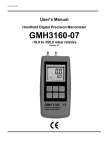
H61.0.21.6C-01 User’s Manual Handheld Digital Precision Manometer GMH3161-01 -1,00 to 25,00 mbar relative Version 6.5 GREISINGER electronic GmbH D - 93128 Regenstauf, Hans-Sachs-Straße 26 H61.0.21.6C-01 User’s Manual GMH3161-01 page 2 of 8 CONTENTS 1 2 3 4 5 6 7 8 GENERAL................................................................................................................................................ 2 1.1 SAFETY REQUIREMENTS....................................................................................................................... 2 1.2 OPERATION AND MAINTENANCE ADVICE................................................................................................ 3 1.3 CONNECTIONS ..................................................................................................................................... 3 1.4 DISPLAY .............................................................................................................................................. 3 1.5 BASIC OPERATION ............................................................................................................................... 3 CONFIGURATION ................................................................................................................................... 4 2.1 UNIT: CHOICE OF THE DISPLAY UNIT .................................................................................................... 4 2.2 P.OFF: AUTO POWER OFF TIME ........................................................................................................... 4 2.3 ADR: BASE ADDRESS OF INTERFACE ..................................................................................................... 4 2.4 OFFS: ADJUSTING SENSOR ZERO DISPLACEMENT ................................................................................ 4 2.5 SCAL: ADJUSTING SENSOR SCALE....................................................................................................... 4 ERROR AND SYSTEM MESSAGES ....................................................................................................... 5 PRESSURE CONNECTION TO THE SENSORS..................................................................................... 5 CALIBRATION SERVICES ...................................................................................................................... 5 THE SERIAL INTERFACE ....................................................................................................................... 6 SPECIFICATION...................................................................................................................................... 7 DISPOSAL NOTES.................................................................................................................................. 7 1 General 1.1 Safety Requirements This device has been designed and tested in accordance with the safety regulations for electronic devices. However, its trouble-free operation and reliability cannot be guaranteed unless the standard safety measures and special safety advises given in this manual will be adhered to when using the device. 1. Trouble-free operation and reliability of the device can only be guaranteed if the device is not subjected to any other climatic conditions than those stated under "Specification". 2. Device and sensors have to be handled with care (don’t throw, hit, etc.). 3. If the device is transported from a cold to a warm environment condensation may cause in a failure of the function. In such a case make sure the device temperature has adjusted to the ambient temperature before trying a new start-up. 4. If device is to be connected to other devices (e.g. via serial interface) the circuitry has to be designed most carefully. Internal connection in third party devices (e.g. connection GND and earth) may result in not-permissible voltages impairing or destroying the device or another device connected. Warning: If device is operated with a defective mains power supply (e.g. short circuit from mains voltage to output voltage) this may result in hazardous voltages at the device (e.g. at sensor socket or interface). 5. If there is a risk whatsoever involved in running it, the device has to be switched off immediately and to be marked accordingly to avoid re-starting. Operator safety may be a risk if: - there is visible damage to the device - the device is not working as specified - the device has been stored under unsuitable conditions for a longer period of time. In case of doubt, please return device to manufacturer for repair or maintenance. _______________________________________________________________________________________________________________________ GREISINGER electronic GmbH Hans-Sachs-Straße 26 D-93128 Regenstauf Fon: 0049-9402 / 9383-0 Fax: 0049-9402 / 9383-33 http://www.greisinger.de e-mail: [email protected] H61.0.21.6C-01 User’s Manual GMH3161-01 page 3 of 8 1.2 Operation And Maintenance Advice • Battery Operation If ´bAt´ are shown in the secondary display the battery has been used up and needs to be replaced. The device will, however, operate correctly for a certain amount of time. If ´bAt´ is shown in the upper display the voltage is too low to operate the device; the battery has been completely used up. Note: The battery has to be taken out, when storing device above 50°C. We recommend to take out battery if device is not used for a longer period of time! • Mains Operation With Power Supply Warning: When using a power supply please note that operating voltage has to be 10.5 to 12 V DC. Do not apply overvoltage!! Cheap 12V-power supplies often have excessive no-load voltage. We, therefore, recommend using regulated voltage power supplies. Trouble-free operation is guaranteed by our power supply GNG10/3000. Prior to connecting the power supply to the mains make sure that the operating voltage stated at the power supply is identical to the mains voltage. 1.3 Connections Connection for pressure tubes: „+“ = higher pressure, „-“ = lower pressure Interface: Connection for el. isolated interface adapter (p.r.t. chapter 6) The mains adapter socket is located at the left side of the device. 1.4 Display Units: an arrow points to the chosen measuring unit SL: no function main display: shows measuring value secondary display: shows min-, max- or hold value Tara: appears if tara-function is activated Logg: not used 1.5 Basic Operation When switching on the device and a zero point adjustment was carried out it shows shortly „nuLL Corr“. On-/Off-Switch ON Tara OFF max Tara: Calling of tara function, zero point adjustment 1 2 3 min/max: Showing the min- resp. max-memory in sec. display Set min Store Store/Quit: Calling of hold function Menu Quit 4 5 6 Set/Menu: Calling of configuration Max Memory: Pressing ´max´ (key 2) shows the maximum of the measured values. Pressing it again hides it. To clear the max memory press key ´max´ for >2 seconds. Min Memory: Pressing ´min´ (key 5) shows the minimum of the measured values. Pressing it again hides it. To clear the min memory press key ´min´ for >2 seconds. Hold Function: By pressing ´Store/Quit´ (key 6) the last measuring value will be held in the secondary display. Pressing it again hides it. Tare Function: By pressing ´Tara´ (key 3) the display will be set to 0. All measurings from then on will be displayed relatively to the set tare value. When tara function is activated, the arrow "Tara" appears in the display. To deactivate tare function press ´Tara´ for >2 seconds. Please Note: Activating/deactivating tara clears the max- & min-memories. Zero-Point Adjustment: If there is no pressure or zero-pressure (absolute) applied to the pressure ports the device will display 0. If there is a permanent deviation (and device is operated under steady conditions), a permanent zero point adjustment can be carried out. To carry out the adjustment press button 3 for approx. 5 seconds (Auto Null will be displayed shortly). The adjustment is done via the OFFSET-value of the sensor (referring configuration menu). Please note: A zero-point adjustment can only be carried out if the difference between the value on display is less than 500 digits! To recall the manufacturer’s calibration press button 3 for approx. 15 seconds. Note: If a zero-point adjustment was carried out, this will be signalled by the short displaying of „Corr“ when switching on the device. _______________________________________________________________________________________________________________________ GREISINGER electronic GmbH Hans-Sachs-Straße 26 D-93128 Regenstauf Fon: 0049-9402 / 9383-0 Fax: 0049-9402 / 9383-33 http://www.greisinger.de e-mail: [email protected] H61.0.21.6C-01 User’s Manual GMH3161-01 page 4 of 8 2 Configuration To change device settings, press Menu (key 4) for 2 seconds. This will call the configuration menu. Pressing key Menu jumps between the parameters. The parameters can be changed with 5 (key 2) or 6 (key 5). Quit (key 6) finishes the configuration and returns to standard measuring operation. 2.1 Unit: Choice Of The Display Unit mbar bar Pa MPa kPa mbar PSI SL Tara AL Logg Choose the desired display unit, the referring unit is displayed by means of a functional arrow in the display. The selection is permanently stored in the device, therefore after power on the unit will instantly reappear. The choice depends on the used sensor. The unit [m] =mH2O is just supported by devices with [m] printed below the display! 2.2 P.oFF: Auto Power Off Time mbar bar PSI Pa MPa kPa SL Tara AL Logg The device will be automatically switched off if no key is pressed/no interface communication takes place for the time of the power off time. The power off time can be set to values between 1 and 120 min. It can be completely deactivated by setting the parameter to ‚P.oFF = oFF“. 2.3 Adr: Base Address of Interface mbar bar Pa kPa MPa mbar PSI SL Tara AL Logg Up to 10 devices of the GMH3xxx- handheld-family can be connected to a serial interface at once (depending on interface converter, e.g. GRS3105: 5 devices). To get access to each device the base addresses of the devices have to be different. For example choose 01 for the first, 11 for the second device and so on. 2.4 OFFS: Adjusting Sensor Zero Displacement A zero displacement can be carried out for the measured value: value displayed = value measured - offset Standard setting: 'off' = 0.0°, i.e. no zero displacement will be carried out. Together with the scale correction (see below) this factor is mainly used to compensate for sensor deviations. Input is in the display unit. 2.5 SCAL: Adjusting Sensor Scale The scale of the measuring can be influenced by this setting (factor is in %): displayed value = measured value * (1+Scal/100) Standard setting: 'off' =0.000, i.e. value is not corrected. Together with the zero displacement (see above) this factor is mainly used to compensate for sensor deviations. _______________________________________________________________________________________________________________________ GREISINGER electronic GmbH Hans-Sachs-Straße 26 D-93128 Regenstauf Fon: 0049-9402 / 9383-0 Fax: 0049-9402 / 9383-33 http://www.greisinger.de e-mail: [email protected] H61.0.21.6C-01 User’s Manual GMH3161-01 page 5 of 8 3 Error And System Messages Display No display or confused characters, device does not react on keypress Meaning Low battery power, device will only continue operation for a short period of time What to do? Replace battery Battery empty Replace battery Mains operation without battery: wrong voltage Sensor defective Value is too low to be displayed, tara is set Check power supply, replace it when necessary Replace battery Check power supply, replace it when necessary Disconnect battery and power supplies, wait shortly, then reconnect Return to manufacturer for repair Check: pressure above 25 mbar? -> measuring value to high Return to manufacturer for repair Check: pressure below -1mbar? -> measuring value to high Return to manufacturer for repair Check: display below -2000 (tara?)? Measured value far out of allowable range Check: pressure not within sensor range? System error Return to manufacturer for repair Battery empty Mains operation without battery: wrong voltage or polarity System error Err.1 Device defective Measured value above allowable range Err.2 Sensor defective Measured value below allowable range Err.4 Err.9 Err.7 4 Pressure Connection To The Sensors • • • For measurements of over pressure (-1.00mbar...25.00mbar): Connect plastic tube with internal dia of 4 mm to pressure port "+". Port "-" will not be used! For measurements of under pressure (-25.00mbar...0.00mbar): Plug the tube to pressure port "-". The measuring range covers then -25.00 to 0.00 mbar. Note: All values are displayed now as positive values. No minus sign will be shown. Example: it is possible to measure under pressure down to -25.00 mbar, the display shows then the value 25.00 (no minus sign). For measurements of pressure differences: Connect both plastic tubes with an internal dia of 4 mm to pressure port "+" and "-"; make sure to apply higher pressure to port "+". 5 Calibration Services Calibration certificates – DKD-certificates – other certificates: If device should be certificied for its accuracy, it is the best solution to return it with the referring sensors to the manufacturer. Only the manufacturer is capable to do efficient recalibration if necessary to get results of highest accuracy! _______________________________________________________________________________________________________________________ GREISINGER electronic GmbH Hans-Sachs-Straße 26 D-93128 Regenstauf Fon: 0049-9402 / 9383-0 Fax: 0049-9402 / 9383-33 http://www.greisinger.de e-mail: [email protected] H61.0.21.6C-01 User’s Manual GMH3161-01 page 6 of 8 6 The Serial Interface By means of the serial interface and a suitable electrically isolated interface adapter (GRS3100, GRS3105 or USB3100) the device can be connected to a computer for data transfer. With the GRS3105 up to 5 devices of the GMH3xxx- series can be connected to one interface (see also manual of GRS3105). To avoid transmission errors, there are several security checks implemented e.g. CRC. The following standard software packages are available: EBS9M: 9-channel software to display the measuring values EASYCONTROL: Universal multi channel software (EASYBUS-, RS485-, or GMH3000- operation possible) for real-time recording and presentation of measuring data of one GMH3xxx device in the ACCESS®-data base format In case you want to develop your own software we offer a GMH3000-development package including: • a universally applicable Windows functions library ('GMH3000.DLL') with documentation that can be used by the most programming languages. • Programming examples Visual Basic 4.0, Testpoint (Keithley Windows measuring software) Note: The measuring and display range values read back from the interface are always in the selected measurement unit (mbar, bar...)! Supported functions: Code 0 3 6 7 12 174 175 176 177 178 179 180 199 Name/Function Read measurement value Read system state Read min memory Read max memory Read ID number Clear min memory Clear max memory Read min measuring range Read max measuring range Read measuring range – measuring unit Read measuring range – decimal point Read kind of measuring of sensor Read kind of measuring of display Code 200 201 202 204 208 214 216 222 223 240 254 Name/Function Read min display range Read max display range Read display range - unit Read display range – decimal point Read # of channels Read scale adjustment [%] Read offset adjustment Read power off time (Conf-P.oFF) Set power off time (Conf-P.oFF) Reset Read program version _______________________________________________________________________________________________________________________ GREISINGER electronic GmbH Hans-Sachs-Straße 26 D-93128 Regenstauf Fon: 0049-9402 / 9383-0 Fax: 0049-9402 / 9383-33 http://www.greisinger.de e-mail: [email protected] H61.0.21.6C-01 User’s Manual GMH3161-01 page 7 of 8 7 Specification Measuring ranges: Display range: Overload: Resolution: Pressure units: Accuracy: (typ.) Measuring rate: Nominal temperature: Sensor: Connection: -1.00 to 25.00 mbar relative (under pressure down to -25.00 mbar, p.r.t. chapter 4) max. 100 mbar rel. (without destruction or recalibration of sensor being necessary) 0.01 mbar (1 Pa) mbar, bar, Pa, kPa, mmHg, PSI, mH2O (display ‚m‘), selectable ±0,3%FS (hysteresis and linearity) ±0,4%FS (temperature dependency 0-50°C) 4 meas./sec 25°C Piezo-resistive relative pressure sensor integrated in device. Suitable for air and non-corrosive and non-ionizing gases and liquids. (Not suitable for water – use air buffering) 2 metal pressure ports for connection to 6 x 1 mm tubes at the top of device (4mm inner tube Ø) Power-Off-Function: Device will be automatically switched off if no key is pressed/no interface communication takes place for the time of the power-off delay. The power-off delay can be set to values between 1 and 120 min.; it can be completely deactivated. Display: Power consumption: Low battery warning: 2 four digit LCDs (12.4mm high and 7 mm high) for measuring values, and for min/ max memories, hold function, etc. as well as additional functional arrows. 6 membrane keys Serial interface (3.5mm jack) can be connected to RS232 or USB interface of a PC via electrically isolated interface adapter GRS3100, GRS3105 or USB3100 (see accessories). 9V battery, type: IEC 6F22 (included in scope of supply) as well as additional d.c. connector (diameter of internal pin 1.9 mm) for external 10.5-12V direct voltage supply. _ (suitable power supply: GNG10/3000) + approx. 0.6 mA ' bAt ' Housing: Dimensions: Weight: Working temperature: Allowable rel. humidity: Storage temperature: impact-resistant ABS, membrane keyboard, transparent panel, Front side IP65 142 x 71 x 26 mm (L x W x D) + metal pressure ports 11mm at top of device approx. 165 g -20...+50°C 0...95 %RH (not condensing) -20...+70°C EMC: The device corresponds to the essential protection ratings established in the Regulations of the Council for the Approximation of Legislation for the member countries regarding electromagnetic compatibility (2004/108/EG). <1% Pushbuttons: Interface: Power supply: Additional fault: 8 Disposal notes This device must not be disposed as ‘residual waste’. To dispose this device, please send it directly to us (adequately stamped). We will dispose it appropriately and environmentally friendly. _______________________________________________________________________________________________________________________ GREISINGER electronic GmbH Hans-Sachs-Straße 26 D-93128 Regenstauf Fon: 0049-9402 / 9383-0 Fax: 0049-9402 / 9383-33 http://www.greisinger.de e-mail: [email protected] H61.0.21.6C-01 User’s Manual GMH3161-01 page 8 of 8 _______________________________________________________________________________________________________________________ GREISINGER electronic GmbH Hans-Sachs-Straße 26 D-93128 Regenstauf Fon: 0049-9402 / 9383-0 Fax: 0049-9402 / 9383-33 http://www.greisinger.de e-mail: [email protected]