1
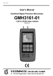
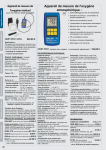
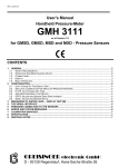
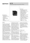
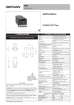
H54.0.01.6C-03 User’s Manual Digital Quick Response Thermometer GMH 3210 For Thermocouple Probes Type J, K, N, S, T as for Version 1.0 GMH 3200 Series Thermometer Thermoelement / Thermocouple WEEE-Reg.-Nr. DE 93889386 GHM Messtechnik GmbH • Standort Greisinger Hans-Sachs-Str. 26 • D-93128 Regenstauf +49 (0) 9402 / 9383-0 +49 (0) 9402 / 9383-33 [email protected] H61.0.2X.6B-01 User’s Manual GMH 3210 page 2 of 12 CONTENTS 1 2 GENERAL NOTE................................................................................................................................... 3 SAFETY ................................................................................................................................................. 3 2.1 INTENDED USE .................................................................................................................................. 3 2.2 SAFETY SIGNS AND SYMBOLS ............................................................................................................. 3 2.3 SAFETY GUIDELINES .......................................................................................................................... 3 3 PRODUCT SPECIFICATION ................................................................................................................. 4 3.1 SCOPE OF SUPPLY............................................................................................................................. 4 3.2 OPERATION AND MAINTENANCE ADVICE .............................................................................................. 4 4 HANDLING ............................................................................................................................................ 5 4.1 DISPLAY............................................................................................................................................ 5 4.2 BASIC OPERATION ............................................................................................................................. 5 4.3 CONNECTIONS .................................................................................................................................. 5 4.4 POP-UP CLIP ..................................................................................................................................... 6 5 START OPERATION ............................................................................................................................. 7 6 CONFIGURATION ................................................................................................................................. 7 7 REMARKS TO SPECIAL FUNCTIONS ................................................................................................. 8 7.1 DISPLAY RESOLUTION ....................................................................................................................... 8 7.2 POWER OFF TIME .............................................................................................................................. 8 7.3 MIN-/MAX-VALUE MEMORY, HOLD FUNCTION ....................................................................................... 8 8 OUTPUT ................................................................................................................................................ 8 8.1 SERIAL INTERFACE ............................................................................................................................ 8 8.2 ANALOGUE OUTPUT – SCALING WITH DAC.0 AND DAC.1 .................................................................... 9 9 INPUT ADJUSTMENT ........................................................................................................................... 9 9.1 ZERO DISPLACEMENT ('OFFSET')........................................................................................................ 9 9.2 DISPLAY CORRECTION FACTOR ('CORR')............................................................................................ 9 10 BASICS OF THERMOCOUPLE TEMPERATURE MEASUREMENTS............................................... 9 11 ERROR AND SYSTEM MESSAGES ................................................................................................ 10 12 SPECIFICATION .............................................................................................................................. 11 13 RESHIPMENT AND DISPOSAL ....................................................................................................... 12 13.1 RESHIPMENT................................................................................................................................ 12 13.2 DISPOSAL INSTRUCTIONS.............................................................................................................. 12 User’s Manual GMH 3210 H61.0.2X.6B-01 page 3 of 12 1 General Note Read this document carefully and get used to the operation of the device before you use it. Keep this document within easy reach near the device for consulting in case of doubt. Mounting, start-up, operating, maintenance and removing from operation must be done by qualified, specially trained staff that have carefully read and understood this manual before starting any work. The manufacturer will assume no liability or warranty in case of usage for other purpose than the intended one, ignoring this manual, operating by unqualified staff as well as unauthorized modifications to the device. The manufacturer is not liable for any costs or damages incurred at the user or third parties because of the usage or application of this device, in particular in case of improper use of the device, misuse or malfunction of the connection or of the device. The manufacturer is not liable for misprints. 2 Safety 2.1 Intended Use The safety requirements (see below) have to be observed. The device must be used only according to its intended purpose and under suitable conditions. Use the device carefully and according to its technical data (do not throw it, strike it, …) Protect the device from dirt. 2.2 Safety signs and symbols Warnings are labeled in this document with the followings signs: Caution! This symbol warns of imminent danger, death, serious injuries and significant damage to property at non-observance. DANGER Attention! This symbol warns of possible dangers or dangerous situations which can provoke damage to the device or environment at non-observance. Note! This symbol point out processes which can indirectly influence operation or provoke unforeseen reactions at non-observance. 2.3 Safety guidelines This device has been designed and tested in accordance with the safety regulations for electronic devices. However, its trouble-free operation and reliability cannot be guaranteed unless the standard safety measures and special safety advises given in this manual will be adhered to when using the device. 1. Trouble-free operation and reliability of the device can only be guaranteed if the device is not subjected to any other climatic conditions than those stated under "Specification". If the device is transported from a cold to a warm environment condensation may cause in a failure of the function. In such a case make sure the device temperature has adjusted to the ambient temperature before trying a new start-up. User’s Manual GMH 3210 H61.0.2X.6B-01 2. _DANGER page 4 of 12 If there is a risk whatsoever involved in running it, the device has to be switched off immediately and to be marked accordingly to avoid re-starting. Operator safety may be a risk if: - there is visible damage to the device - the device is not working as specified - the device has been stored under unsuitable conditions for a longer time. In case of doubt, please return device to manufacturer for repair or maintenance. 3. When connecting the device to other devices the connection has to be designed most thoroughly as internal connections in third-party devices (e.g. connection GND with protective earth) may lead to undesired voltage potentials that can lead to malfunctions or destroying of the device and the connected devices. This device must not be run with a defective or damaged power supply unit. Danger to life due to electrical shock! _DANGER 4. _DANGER 5. Do not use these products as safety or emergency stop devices or in any other application where failure of the product could result in personal injury or material damage. Failure to comply with these instructions could result in death or serious injury and material damage. This device must not be used at potentially explosive areas! The usage of this device at potentially explosive areas increases danger of deflagration, explosion or fire due to sparking. _DANGER 3 Product Specification 3.1 Scope of supply The scope of supply includes: Device, incl. 9V battery block Operation manual 3.2 Operation and maintenance advice • Battery operation: If ‘bAt’ is shown in the lower display the battery has been used up and needs to be replaced. However, the device will operate correctly for a certain time. If ‘bAt’ is shown in the upper display the voltage is too low to operate the device; the battery has been completely used up. Battery change: p.r.t. chapter The battery has to be taken out, when storing device above 50 °C. We recommend taking out battery if device is not used for a longer period of time. After recommissioning the real-time clock has to be set again. • Mains operation with power supply When using a power supply please note that operating voltage has to be 10.5 to 12 V DC. Do not apply overvoltage!! Cheap 12V-power supplies often have excessive no-load voltage. We, therefore, recommend using regulated voltage power supplies. Trouble-free operation is guaranteed by our power supply GNG10/3000. Prior to connecting the power supply to the mains make sure that the operating voltage stated at the power supply is identical to the mains voltage. Treat device and sensor carefully. Use only in accordance with above specification. (do not throw, hit against etc.). Protect plug and socket from soiling. To disconnect thermocouple sensor plug do not pull at the cable but at the plug. Selection of types of thermocouples: Prior to carrying out a measurement make sure to check if device is set to the thermocouple type used (type is shown on the display shortly after unit has been switched on). Unless the correct thermocouple is set, temperature measurements will be incorrect! User’s Manual GMH 3210 H61.0.2X.6B-01 page 5 of 12 4 Handling 4.1 Display 1 Main display: Currently measured temperature 2 Warnind triangle: indicates a low battery 3 Secondary display: Display of min, max or hold values 4 Corr-arrow: indicates that correction factor is activated 5 Offset-arrow: indicates that zero point offset (offset) is activated. 6 Min/Max/Hold: shows if a min., max. or hold value is displayed in the secondary display. 4.2 Basic Operation On/Off key + ON OFF 1 Tara max 2 3 1 Set min Store Menu 4 min/max when taking measures: press short: shows the min./max. value press again: hides min./max. value press 2 sec.: clears particular value Quit 5 6 ON OFF Tara 2 Set max min 3 Store Menu 4 Tara: no function Quit 5 6 Set/Menu: press short: invokes configuration menu Store/Quit: press short: hold-function, the last measuring value will be held in the secondary display. Set/Menu: Acknowledge setting, return to measuring. 4.3 Connections Output: Connection for optically isolated interface adapter or for analog output (please refer to chapter 8) Probe connection Power supply: the mains adapter socket is located at the left side of the device. User’s Manual GMH 3210 H61.0.2X.6B-01 page 6 of 12 4.4 Pop-up clip Handling: • Pull at label “open” in order to swing open the pop-up clip. • Pull at label “open” again to swing open the pop-up clip further. Pop-up clip closed Pop-up clip at position 90° Pop-up clip at position 180° Function: • The device with a closed pop-up clip can be plainly laid onto a table or attached to a belt, etc. • The device with pop-up clip at position 90° can be set up on a table, etc. • The device with pop-up clip at position 180° can be suspended from a screw or the magnetic holder GMH 1300. Device attached to a belt Device set up on a table Device suspended from magnetic holder GMH 1300 User’s Manual GMH 3210 H61.0.2X.6B-01 page 7 of 12 5 Start Operation Connect sensor, turn on device via 1 ON OFF CAL 2 Set key. max 3 min Store Menu 4 Quit 5 6 After segment test the device displays some configuration: • If a zero point adjustment was carried out the display shows shortly „nuLL Corr“. After that the device is ready for measuring. 6 Configuration To change device settings, press Menu (key 4) for 2 seconds. This will call the configuration menu. Pressing key Menu jumps between the parameters. The parameters can be changed with (key 2) or (key 5). Quit (key 6) finishes the configuration and returns to standard measuring operation. Parameter ‚Menu‘ Values or ni.cr , n , S , t , J Description Type: Selection oft he Thermocouple-Type ni.cr: type K, NiCr-Ni n: type N, NiCrSi-NiSi S: type S, Pt10Rh-Pt t: type T, Cu-CuNi J: type J, Fe-CuNi ºC, ºF Unit: Selection of Temperature Unit 1ºC, 0.1ºC, Auto Resolution: Selection of Display Resolution (Not for Type S) Attention: When Type S is selected the resolution is always 1°C! 0.950...1.200 Display correction factor (refer to chapter 9.2) off Factor deactivated (=1.000) 1 … 120 Auto Power-Off time in minutes oFF Auto Power-Off deactivated 01, 11 … 91 Base address of interface -10ºC...10ºC bzw. -18ºF...18ºF oFF The offset of sensor will be displaced by this value to compensate for deviations in the probe or in the measuring device. Zero displacement inactive (=0.00) SEr, dAC Output: function of device output: serial interface or analogue output oFF No output function, lowest power consumption Output Offset when output = Analogue outeput -220ºC...1372ºC (depending on selected range) Input of the temperature at which 0V should be output Output grade when output = Analogue Output -220ºC...1372ºC (depending on selected range) Input of the temperature at which 1V should be output H61.0.2X.6B-01 User’s Manual GMH 3210 page 8 of 12 7 Remarks to Special Functions 7.1 Display Resolution Standard setting: 'Auto', i.e. the device automatically switches over to the optimum resolution between 1° and 0.1°. If temperatures to be measured are near the switching threshold, a fixed resolution may be better, e.g. for easy recording. In such a case please select the optimum resolution manually. Independent from this setting, type S measurings are always in 1° resolution! 7.2 Power off Time If there won’t be pressed any key and no interface communication takes place for the time of the power off time setting (P.Off), the device will be switched off automatically to save battery power. If P.oFF = oFF then the automatic switch off is deactivated. 7.3 Min-/Max-value memory, Hold function • Min-/Max-value memory: the max. and the min. value will be memorised. • Hold function: Press button 6 to store current value. For more Information please refer to chapter 4.2 8 Output The output can be used as serial interface (for USB 3100, USB 3100 N, GRS 3100 or GRS 3105 interface adapters) or as analog output (0-1V). If none of both is needed, we suggest to switch the output off, because battery life then is extended. 8.1 Serial Interface By means of the serial interface and a suitable electrically isolated interface adapter (USB 3100, USB 3100 N, GRS 3100 or GRS 3105) the device can be connected to a computer for data transfer. With the GRS 3105 up to 5 devices of the GMH3xxx- series can be connected to one interface (see also manual of GRS 3105). As a precondition the base addresses of all devices must not be identical, make sure to configure the base addresses accordingly (refer menu point “Adr.” in chapter 6). To avoid transmission errors, there are several security checks implemented e.g. CRC. The following standard software packages are available: GMHKonfig: Software for a comfortable editing of the device (e.g. Material selection…) EBS 20M / 60M: 20-/60-channel software to display the measuring values In case you want to develop your own software we offer a GMH3000-development package including: a universally applicable Windows functions library ('GMH3000.DLL') with documentation that can be used by the most programming languages. Suitable for Windows XP™, Windows Vista™, Windows 7™ Programming examples Visual Basic 4.0™, Delphi 1.0™, Testpoint™ Note: The measuring and range values read via interface are always in the selected display unit (°C/°F)! Supported interface functions: Code 0 3 6 7 12 174 175 194 195 199 200 Name/Function Read nominal value Read system status Read min. value Read max. value Read ID-no. Delete min. value Delete max. value Set display unit Set decimal point in display (255=Auto) Read meas. type in display Read min. display range Code 201 202 204 208 216 217 218 219 240 254 Name/Function Read max. display range Read unit of display Read decimal point of display Read channel count Read offset correction Set offset correction Read corr. Factor (950..1200) Set corr. factor (950..1200) Reset Read program identification User’s Manual GMH 3210 H61.0.2X.6B-01 page 9 of 12 8.2 Analogue Output – Scaling with DAC.0 and DAC.1 Note: Analogue output can not be used during logger recordings With the DAC.0 and DAC.1 values the output can be rapidly scaled to your efforts. Keep in mind not to connect low-resistive loads to the output, otherwise the output value will be wrong and battery life is decreased. Loads above ca 10kOhm are uncritical. If the display exceeds the value set by DAC.1, then the device will apply 1V to the output If the display falls below the value set by DAC.0, then the device will apply 0V to the output In case of an error (Err.1, Err.2, no sensor, etc.) the device will apply slightly above 1V to the output. plug wiring: GND Attention! the 3rd contact has to be left floating! Only stereo plugs are allowed! +Uout 9 Input Adjustment 9.1 Zero Displacement ('Offset') A zero displacement can be carried out for the measured temperature: temperature displayed = temperature measured - offset Standard setting: 'off' = 0.0°, i.e. no zero displacement will be carried out. The zero displacement is mainly used to compensate for sensor deviations. Unless 'off' is set, this value will be displayed shortly after the device is switched on; during operation it will be identified by means of the offset arrow in the display. 9.2 Display Correction Factor ('Corr') This factor is used to compensate for losses of transfer in case of surface measurements, occurring if the object to be measured is extremely hot but will be cooled by lower ambient temperatures. The same can be true for sensors with a large mass. Unless 'off' is set (standard setting: 'off' =1.000), this value will be displayed shortly after the device is switched on; during operation it will be identified by means of the Corrarrow in the display. temperature displayed [°C] = temperature measured [°C] * Corr or temperature displayed [°F] = (temperature measured [°F]-32°F) * Corr + 32°F 10 Basics of Thermocouple Temperature Measurements The right thermocouple type has to be selected prior to measuring (p.r.t. Device Configuration). Otherwise the instrument will display a wrong value! The device is optimised for type K usage. Temperature differences between the instrument and the probe connector may produce measuring errors, especially when using other types than type K. Therefore wait after connecting or touching the connector until the temperatures have adjusted (can take several minutes, depending on the temperature differences). The device is suitable to measure large temperature ranges. But consider the allowable range of the probe! When measuring air temperature the probe has to be dry. Otherwise the cold due to the evaporation causes too low measurings. User’s Manual GMH 3210 H61.0.2X.6B-01 page 10 of 12 11 Error And System Messages Display Meaning Remedy low battery voltage, device will continue to work for a short time replace battery If mains operation: wrong voltage replace power supply, if fault continues to exist: device damaged replace battery Check/replace power supply, if fault continues to exist: device damaged low battery voltage If mains operation: wrong voltage No display or weird display low battery voltage If mains operation: wrong voltage system error Device does not react on keypress device defective SenS Sensor error: no sensor connected Erro sensor/cable or device defective Err.1 Value exceeding measuring range Err.2 Err.7 sensor/cable defective Value below display range sensor/cable defective system error Far out of allowable operation temperature replace battery Check/replace power supply, if fault continues to exist: device damaged Disconnect battery or power supply, wait some time, re-connect return to manufacturer for repair Connect sensor to socket return to manufacturer for repair Check: Is the value exceeding the measuring range specified? ->temperature too high! -> replace Check: Is the value below the measuring range specified? -> temperature too low! -> replace return to manufacturer for repair -25..50°C are allowable User’s Manual GMH 3210 H61.0.2X.6B-01 page 11 of 12 12 Specification Thermocouple: J, K, N, S or T Probe Connection: Socket for flat pin plug, free from thermo voltage for type K Resolution: 0,1°C or 1°C 0,1°F or 1°F for types J, K, N, T 1°C 1°F for type S Meas. Ranges: Type K: (NiCr-Ni) Type J: (Fe-CuNi) Type T: (Cu-CuNi) Type N: (NiCrSi-NiSi) Type S: (Pt10Rh-Pt) 0,1°C -65,0... +300,0 °C -50,0... +225,0 °C -65,0... +250,0 °C -100,0... +380,0 °C - 1°C -220... +1372 °C -140... +950 °C -220... +400 °C -200... +1300 °C -50... +1768 °C 0.1F -85,0... +572,0 °F -58,0... +437,0 °F -85,0... +482,0 °F -148,0... +716,0 °F - 1°F -364... +2500 °F -220... +1742 °F -364... +752 °F -328... +2372 °F -58... +3214 °F Accuracy: (for thermocouples DIN EN 60584) ±1 digit (at nominal temperature) Range 0,1 °C/°F Range 1 °C/°F Type K: ±0,03% of m.v. ±0,05%FS ±0,08% of m.v.±0,1%FS Type J: ±0,03% of m.v.±0,08%FS ±0,08% of m.v.±0,1%FS Type T: ±0,03% of m.v.±0,1%FS ±1°C (T > -100°C), ±1°C ±1Digit (T < -100°C) Type N: ±0,03% of m.v.±0,05%FS ±0,08% of m.v.±0,1%FS (T > -100°C) ±1°C, ±0,1%FS (T < -100°C) Type S: ±0,1% of m.v.±0,1%FS (T > 200°C), ±1°C ±0.1%FS (T<200°C) Temperature drift 0,01 %/K Point of Comparison ±0,3 °C Nominal temperature 25 °C Display: Pushbuttons: Output: Output function: Interface: Analog output: 2 four digit LCDs (12.4mm high and 7 mm high) for measuring values, and for min/ max memories, hold function, etc. as well as additional functional arrows. 6 membrane keys 3.5 mm audio plug, stereo selectable as serial interface or analog output Serial interface (3.5mm jack) can be connected to USB or RS232 interface of a PC via electrically isolated interface adapter USB3100, USB 3100 N, GRS3100 or GRS3105 (see accessories). 0 ... 1 Volt, freely scaleable (resolution 12 bit) Power supply: 9V battery, type: IEC 6F22 (included in scope of supply) as well as additional d.c. connector (diameter of internal pin 1.9 mm) for external 10.5-12V direct voltage supply. _ + (suitable power supply: GNG 10 / 3000) Power consumption: approx. 260µA when output switched off approx. 400µA when output is serial interface (at 1 reading per second) approx. 500µA when output is analogue output (without load) Low battery warning: ' bAt ' Working conditions: -20 ... +50 °C, 0 ... 95 %RH (not condensing) Storage temperature: -20 ... +70 °C Housing: Dimensions: Weight: impact-resistant ABS, membrane keyboard, transparent panel, Front side IP65 142 x 71 x 26 mm (L x W x D) approx. 155 g EMC: The device corresponds to the essential protection ratings established in the Regulations of the Council for the Approximation of Legislation for the member countries regarding electromagnetic compatibility (2004/108/EG). Additional fault: <1% User’s Manual GMH 3210 H61.0.2X.6B-01 page 12 of 12 13 Reshipment and Disposal 13.1 Reshipment All devices returned to the manufacturer have to be free of any residual of measuring media and other hazardous substances. Measuring residuals at housing or sensor may be a risk for persons or environment Use an adequate transport package for reshipment, especially for fully functional devices. Please make sure that the device is protected in the package by enough packing materials. 13.2 Disposal instructions Batteries must not be disposed in the regular domestic waste but at the designated collecting points. The device must not be disposed in the unsorted municipal waste! Send the device directly to us (sufficiently stamped), if it should be disposed. We will dispose the device appropriate and environmentally sound.