1
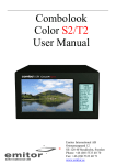
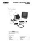
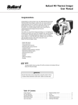
Accessories for Bullard TI Commander
User Manual
This Manual Covers:
• Digital Image Capture
• Relative Heat Indicator
• Digital Zoom
• Video Out
• Transmitter
• Truck Mount
• Clamp
• Tripod
• Straps
• Glare Shield
WARNING
Read all instructions and warnings before using this
product. Failure to observe these instructions could
result in death or serious injury.
Table of Contents
Diagram . . . . . . . . . . . . . . . . . . . . . . . . . . . . . . .2
Digital Image Capture . . . . . . . . . . . . . . . . . . . .3
Relative Heat Indicator . . . . . . . . . . . . . . . . . . .4
Digital 2X Zoom . . . . . . . . . . . . . . . . . . . . . . . . . .5
Video Output . . . . . . . . . . . . . . . . . . . . . . . . . . . .4
Transmitter . . . . . . . . . . . . . . . . . . . . . . . . . . . . . . . . . . . . 5
Wireless Receiver . . . . . . . . . . . . . . . . . . . . . . . . . . . . . 5
Receiving Antenna . . . . . . . . . . . . . . . . . . . . . . . . . . . . . 6
FCC Notice . . . . . . . . . . . . . . . . . . . . . . . . . . . . . . . . . . . . 7
Truck Mount Direct Charge System . . . . . . . . . . . . 8
Tripod and Clamp System . . . . . . . . . . . . . . . . . . . . . . 9
Field Replaceable Straps . . . . . . . . . . . . . . . . . . . . . 10
Glare Shield . . . . . . . . . . . . . . . . . . . . . . . . . . . . . . . . . . 10
Order Information . . . . . . . . . . . . . . . . . . . . . . . . . . . .11
Top Strap (12)
Rear Boot
Polycarbonate
Display Cover
Image Capture
(Optional) (4)
LCD Screen (9)
Lens Bezel (8)
Lens
Battery
Compartment (7)
2X Digital Zoom
(Optional) (5)
On/Off/ Sleep Button (1)
Relative Heat Indicator™ (Optional) (6)
Transmit Button
(Optional) (3)
Thermal Throttle (2)
Pistol Grip (10)
Diagram
Figure 1
2
Charge and Data
Output Port (11)
Accessories for Bullard TI Commander
User Manual
Digital Image Capture
Capturing Digital Images: The Bullard TI Commander can
be equipped with digital image capture capability. This
enables the capture of still images for later download and
retrieval via a personal computer. To take a digital image
(or picture), press the gray button on the top right side of
the TI Commander. The image will freeze briefly, the
graphics will momentarily disappear, and the number of
pictures remaining, indicated at the bottom right portion
on the screen, will decrease by one. The TI Commander can
store up to 24 digital thermal images.
NOTE
Pressing and holding the PIC button will
result in continuous picture capture.
Downloading Digital Images: To download digital images to
a personal computer, first install the accompanying
software compact disc provided in the TI Commander case
labeled “TI Commander Image Capture Software”. Load
the CD into your computer’s CD drive and if the program
does not autostart, then run the program SETUP.EXE.
Follow the instructions in the install process. The setup
program will create a directory named TI Commander. Run
“TI Commander Download” in this directory to launch the
download program.
Transfer and Store Images
Connect the data cable to your TI Commander via the 5 pin
connector. Connect the other end of the data cable to a
serial port (RS-232) connector on a personal computer. The
software should establish an automatic connection with
the TI Commander. If necessary, manually establish
communication between your PC and the TI Commander by
clicking on the button marked
“Connect to TI
Commander”. You may also wish to update your TI
Commander’s internal clock to the time and date currently
set on the PC. The TI Commander clock is displayed on the
left side of the program. To synchronize the TI Commander
clock with the PC clock, click on the button marked “Update
TI Commander to PC Time and Date”.
NOTE
To set the directory in which you wish to save your
downloaded thermal images, click on the button marked
“Choose Folder”. A window will appear enabling you to
select the desired directory and create a file name prefix
for the files to be downloaded and saved.
Images are not automatically erased from your TI
Commander memory once downloaded. To erase all
images from the TI Commander memory, click on the
button marked “Erase Images from Camera Memory”. The
TI Commander will now be ready to capture 24 new
images.
To exit the program, click on the button marked “Exit”.
NOTE
The software provided is Microsoft
Windows® compatible and has been
tested on Windows 98, Windows 2000,
and Windows XP.
All images are captured with the date and
time overlayed in the lower corner of the
image. Images are saved in grayscale and
include a time/date stamp corresponding
to the time and date that the image was
captured.
NOTE
Your TI Commander is supplied with a
cord for downloading thermal images to
your PC. The standard cord connects to
the TI Commander on one end, and the
other end connects to the serial port on a
computer.
Some newer types of
computers may not be equipped with this
serial port. If your computer does not
have a serial port, Bullard will provide you
a USB adaptor(part #USBADAPTOR) and
software specific to the use of that
adaptor in order to effectively download
images. Please contact Bullard Customer
Service at (800) 227-0423, and we will
send you this adaptor and software free
of charge.
Digital Image Capture
The TI Commander clock is powered
independently by an internal lithium
battery. This battery will power the clock
continuously for 6 -8 years, with or
without the TI Commander NiMH battery
installed. Replacement of the lithium
battery should only be performed by
Bullard Authorized Service
To download images from the TI Commander, click on the
button marked “Save New Pictures”. This will begin the
download process. Stored images will be saved to the
directory you have selected. The saved picture will begin
appearing in the window to the right indicating that the
image is downloading. To skip a picture download or
cancel the download process, click on the appropriately
marked buttons.
3
Relative Heat Indicator (RHI)
The Bullard TI Commander can be equipped with
temperature measurement capability (Item 6, Figure 1).
If equipped, the right side of the display will show a bar
graph or Relative Heat Indicator (RHI). The RHI will
indicate the approximate temperature of the object viewed
within the “crosshairs” shown in the middle of the screen.
The accuracy of the RHI is dependent on numerous factors
including the distance from the object being viewed and its
emissivity, which is the object’s ability to radiate heat. The
Bullard TI has a preset emissivity corresponding with
typical residential wood construction. Objects with
emissivities that vary greatly from this will reduce the
accuracy of the temperature indication. Additionally,
temperature measurement accuracy decreases as the
distance from the object in the “crosshairs” increases as
well as other factors such as atmosphere contamination
(i.e. smoke, fog, dust, or condensation on the lens).
The RHI provides a quick reference to compare objects of
similar emissivities to serve as a guide to pinpoint intense
heat sources. The color on the RHI will change from green
(low heat), to yellow (significant heat), to red (intense heat)
to correspond with the temperature of the object in the
“crosshairs”.
Digital 2X Zoom
RHI/2X Digital Zoom/Video Output
The Bullard TI Commander can be equipped with digital 2X
zoom capability. To activate the digital zoom feature, press
the white button located next to the red “On/Off” button
(Item 1, Figure 1). The image on the display will toggle
to a 2X image, and the symbol “2X” will appear in the
bottom left corner of the screen. To deactivate the zoom
feature, press the white button again and normal viewing
will resume.
4
NOTE
The RHI, battery, transmitter, and image
capture graphic overlays do not appear in
2X mode. Images captured in zoom mode
are saved in normal (1X) mode.
Video Output
The Bullard TI Commander has built in video out capability.
With the optional video-out RCA cable (part number
CMDRCACABLE), you can output the displayed thermal
imagery to an external monitoring or recording device such
as a TV, VCR, or personal computer. To output video to an
external device, connect the video cable to your TI
Commander via the 5 pin connector (Item 11, Figure 1).
Connect the other end via the optional RCA connector to
the external device. Adjust the external device to the
appropriate setting and/or configuration (refer to the
device’s instruction manual) to capture the video stream.
NOTE
The video output feature will also function
in sleep mode. The CMDRCACABLE is not
designed for high heat environments.
Accessories for Bullard TI Commander
User Manual
Wireless Remote Transmitter/Receiver
Use and Operation
Transmitter - Four Channel
Using the Wireless Remote Video Transmitting
Feature: The Bullard TI Commander can be ordered with a
factory installed wireless remote transmitter. The
transmitter sends a signal to a remote receiver, which
connects to any suitable monitor or recording device. The
receiver can be powered by either a 110 VAC adapter or a
15 VDC adapter. The wireless remote transmitter can be set
to transmit on one of four different channels. This feature
allows incident commanders the opportunity to monitor up
to four different Bullard TI Commanders being used at the
same site.
Activating the Transmitter: To initiate transmission on
the Bullard TI Commander, press the black transmitter
button marked “XMIT” (Item 3, Figure 1). A “1” will
appear on the top left corner of the TI Commander display
indicating that the unit is transmitting on channel 1.
Selecting the Transmitting Channel: The Bullard TI
Commander can transmit on one of four different channels.
To set the channel option on the Bullard TI Commander,
press the black transmit button and cycle through the
channels until the desired channel is reached. The number
on the top left corner of the display will indicate the
transmitter channel.
Deactivating the Transmitter: To shut off the
transmitter, press the black transmit button, cycling
through the channels, until the number on the top left
corner of the display no longer appears.
Selecting the Channel on the Receiving Control
Unit: The receiving control unit channel must be set to the
same channel as the thermal imager transmitter being
monitored. Select channel 1, 2, 3, or 4 by pointing the
indicator knob, located on the rear of the unit, to the
appropriate channel.
Transmitter - Two Channel
Using the Wireless Remote Video Transmitting
Feature: The Bullard TI Commander can be ordered with a
factory installed wireless remote transmitter. The
transmitter sends a signal to a remote receiver, which
connects to any suitable monitor or recording device. The
receiver can be powered by either a 110 VAC adapter or a
15 VDC adapter. The wireless remote transmitter can be set
to transmit on one of two different channels. This feature
allows incident commanders the opportunity to monitor up
to two different Bullard TI Commanders being used at the
same site.
Selecting the Transmitting Channel: The Bullard TI
Commander can transmit on one of two different channels.
To set the channel option on the Bullard TI Commander,
press the black transmit button and cycle through the
channels until the desired channel is reached. The letter on
the top left corner of the display will indicate the
transmitter channel.
Deactivating the Transmitter: To shut off the
transmitter, press the black transmit button, cycling
through the channels, until the letter on the top left corner
of the display no longer appears.
Selecting the Channel on the Receiving Control
Unit: The receiving control unit channel must be set to the
same channel as the thermal imager transmitter being
monitored. Select channel A or B by moving the selector
switch, located on the rear of the unit, to the appropriate
channel.
NOTE
The TI Commander transmitter will not
function while the unit is in sleep mode.
Wireless Receiver Assembly and Operating
Instructions
Before assembling your Bullard Wireless Remote Receiver,
please ensure you have the following parts.
• Omni-Directional Antenna
• 50 ohm Coaxial Cable
• Receiver Control Unit
• AC Power Adapter
• DC Power Adapter
• Video Cable with BNC to RCA Adapter
• FCC Registration Form
If you are missing any of these components, please contact
Bullard Sales Support at 877-BULLARD (285-5273).
CAUTION
Putting the thermal imager in the sleep mode also puts
the transmitter in “sleep.” Using the remote video
transmitter feature slightly reduces the continuous
operation time of the battery. Failure to note this
information may affect use-time of the thermal imager.
Wireless Remote Transmitter/Receiver
NOTE
The TI Commander transmitter will not
function while the unit is in sleep mode.
Activating the Transmitter: To initiate transmission on
the Bullard TI Commander, press the black transmitter
button marked “XMIT” (Item 3, Figure 1). An “A” will
appear on the top left corner of the TI Commander display
indicating that the unit is transmitting on channel A.
5
Receiving Antenna Assembly
Brass Nut
Magnetic Mount Assembly Instructions
•Position “O” ring around bushing on magnetized base.
•Affix receiving antenna to base.
O-Ring
Permanent Mount Assembly Instructions
Figure 2
•Refer to Figure 1 for an assembly diagram. The mount
requires a 3/4" (19mm) hole in a flat area with a
thickness of (0.5mm to 1.0mm) .020" to .040".
•Feed the lead-in cable from the top until the bushing
assembly is in position to drop into the hole. The bushing
should be tilted at a slight angle and fed into the hole.
The threaded top of the bushing will not fall through the
hole.
• Thread the brass nut onto the bushing. Be sure the Oring is in the groove of the brass nut before tightening.
The brass nut should be tightened until it comes in
contact with the surface and the O-ring is compressed.
Installing BNC Connector
• Refer to diagrams in Figures 4, 5, and 6 while
performing the following steps.
• Trim cable as shown taking care not to damage the
inner conductor or braid.
• Slip crimp sleeve over cable. Place inner conductor into
contact. Note that the end of contact and inner
dielectric must be butting and square. Crimp with
appropriate tooling.
• Flair outer braid, and gently but firmly push the contact
into the connector housing until a snap is felt, indicating
the contact is in place. Slip the crimp sleeve in place,
butting the flange against the connector body, and
crimp with appropriate tooling.
Receiver to Receiving Antenna Assembly
Receivinig Antenna Assembly
Connecting the Receiving Antenna to the
Receiving Control Unit
Connect the receiving antenna to the top of the receiver
control unit using the coaxial cable supplied with the
antenna.
6
(B)
(C)
Alignment Ring
(Optional for 3⁄4" hole)
Mount Shank
⁄32"
5
⁄32"
Bushing Assembly (F)
Figure 3
Connecting the Receiving Control Unit to a
monitor and/or receiving device
Connect the receiver control unit to a monitor and/or
receiving device using the video cable supplied. Attach
one end of the cable to your monitor and/or receiving
device's input ports. Connect the other end to one of the
three video out connectors on the receiving control unit
(note that one of the connectors is an RCA connector; the
other two are BNC connectors – a BNC to RCA connector
is included). The additional video output connectors can be
used to send the transmission to another TV or VCR. The
receiver control unit can also be connected to a desktop
or laptop computer via a RCA to USB attachment (Sold
separately). For additional video cable, contact Bullard
Customer Service at 877-BULLARD (285-5273).
Powering the Receiving Control Unit
Connect either the AC or DC adapter to the power input
port on the receiving control unit. When power is supplied,
a red LED on the front panel will illuminate.
Selecting the Channel on your monitor
In order to view the transmitted image, your monitor
should be set to video input or auxiliary channel. Some
monitors require a remote control to access the video or
auxiliary channel. See your monitor’s owner's manual for
further information.
Buttting
Flange
Crimp Sleeve
Inspection Hole
(4mm)
(D)
Lead-in cable (E)
13
(10mm)
(A)
Contact
5
⁄16"
(18mm)
Butt Square
Figure 4
Figure 5
Crimp
Area
Figure 6
Crimp
Area
Accessories for Bullard TI Commander
User Manual
FCC Notice
Receiver Specifications
FCC Registration Form
Fill out the Federal Communications Commission (FCC)
registration form and send it to the address noted on the form.
The form must be submitted to ensure the proper licensing with
the FCC.
Dimensions ....................................1.5" x 4.5" x 5"
(including protrusions)
Weight ............................................16 oz.
Power Requirements ....................11-14.5 VDC (center pos.)
Power Consumption......................250 mA
Power Input .................................. Coaxial 2.1 mm by 5.5 mm
center-positive connector
Receiving Frequency ....................2.45 GHz or 2.48 GHz
(2 Channel)
Receiving Frequency ....................2.456 GHz, 2.463 GHz,
2.470 GHz, or 2.477 GHz.
(4 Channel)
Video Outputs ................................Two 75-ohm 1-Volt P-P
Video outputs (female BNC)
This equipment has been tested and complies with Part 90 of the
FCC Rules. These limits are designed to provide reasonable
protection against harmful interference. This equipment
generates, uses and can radiate radio frequency energy, and, if
not installed and used in accordance with the instructions, may
cause harmful interference to radio communications. However,
there is no guarantee that interference will not occur in a
particular installation. If this equipment does cause harmful
interference to radio or television reception, which can be
determined by turning the equipment off and on, the user is
encouraged to try to correct the interference by one or more of
the following measures:
• Change receiver and transmitter channel
• Reorient or relocate the receiving antenna
• Increase the separation distance between the affected
equipment and receiver
• Connect the affected equipment into an outlet on a circuit
different from that to which the receiver is connected
• Consult Bullard or an experienced radio/TV technician for
help
Any changes or modifications not expressly approved by the
manufacturer could void the user’s authority to operate the
equipment.
To ensure licensing, you must fill out and return the FCC
Registration form included with this product.
FCC Notice
7
Truck Mount Direct Charge System
Mounting the Truck Mount Direct Charge System: The
truck mount unit (Figures 8-10) can be mounted to a vehicle
or on a wall by using the mounting gasket and attachment
hardware provided. On each side of the truck mount there are
4 holes. The holes on the top, right, and left panels are for
attaching the unit to a truck. The hole at the bottom is for the
power supply cable.
Begin the installation process by finding a location to mount
the direct charge system and drill the appropriate holes.
Remember that a power supply will need to be located close to
the truck mount in order to charge the unit. Leave room for
inserting and removing the TI Commander from the charger.
Also choose a location that enables visibility of the charging
LEDs and easy access to cables.
Figure 8 - Wiring for deck mounting
Power Supply Cable Installation: Use the following
procedures for installation of the power supply cable to the
vehicle. The power supply cable is provided with two free wire
ends for ready hardwire installation.
1. From the outside, pass the power supply cable (plug end
first) (Figure 10) through the pass-through hole in the
selected side of the truck mount.
2. Select the appropriate anti-rattle pad for the mounting
location chosen. Pass the free end of the power supply cable
through the large hole near the center of the anti-rattle pad
and through the appropriate hole in the vehicle panel. Place
the truck mount in position on the panel and secure it with
the 1/4"-28 stainless steel flat head screws and nuts
provided (four screws are used for horizontal panel
mounting; three for vertical panel mounting). Tighten the
screws securely. Install the inner anti-rattle pad by peeling
off the paper backing and pressing the pad into place in the
bottom of the truck mount. Press firmly to set the adhesive.
3. Once the truck mount is attached, the charger unit needs to
be assembled. Begin by making sure the charger system is
positioned in the truck mount correctly.The faceplate on the
charger should be facing outward and the Bullard logo
should be on the left. Once the charger is positioned
correctly, it will be held in place by snapping in the two black
fasteners provided. Remove the charger from unit and
insert AC or DC adapter cord into charger. Place the charger
back into the truck mount unit and reattach plate with the
black fasteners provided.
4. Cut the free end of the power supply cable to length as
required. Connect the free end of the cable to a 3 Ampere
fuse in a vehicle fuse box providing 12 – 24VDC.
CAUTION
Figure 9 - Wiring for wall mounting
Figure 7
The power supply cable must be connected correctly to
properly function. The power cable should be connected
so that the inner sleeve of the power plug is (+) and the
outer sleeve of the power plug is (–) (Figure 7).
Incorrect connection of the power supply cable may
damage the unit. Failure to follow these instructions may
result in minor injury and/or equipment damage.
Truck Mount Direct Charge System
Negative (–)
8
Positive (+)
Figure 10
Power Supply Cable - Plug End
Inner sleeve is (+). Outer sleeve is (–).
Item 1
Item 3
Item 2
Figure 11
Using the Truck Mount Direct Charge System: There
are three holes in the plate covering the charger. One hole is
for the direct charge cable and two are to allow the user to
view the LED lights. Insert one end of the direct charge cable
into the hole provided on the right (Figure 11,
item 1). Insert the opposite end of the direct charge cable
into the direct charge port located on the handle of the thermal
imager. A red light will illuminate on the charger to indicate that
the camera battery is charging (Figure 11, item 2). When
the light on the charger turns to green, your battery will be
fully charged. You may leave the battery in the charger
indefinitely. A battery in the charger and a battery installed in
the camera may be charged simultaneously. There is a second
indicator light for the battery in the charger (Figure 11,
item 3). Charging both batteries at the same time will not
cause any damage to the batteries or charging unit.
Accessories for Bullard TI Commander
User Manual
Tripod and Clamp System
The tripod system is designed to hold a thermal imager in
place for extended periods of time. The tripod system
consists of the tripod, mounting bracket, and security
strap.
The clamp system is designed to allow the thermal imager
to clamp to ladders, light towers, and command vehicles.
The clamp system consists of a tripod head, clamp,
mounting bracket, and security strap (Figure 13).
Attaching Tripod to Clamp: Screw tripod head onto
clamp using stainless steel stud provided.
Adjusting Height of Tripod:
1. Pull all three legs outward away from the center post as
far as they will go.
2. Extend each leg of the tripod by pulling the clamp lever
away from the leg, drawing the lower section of the leg
out fully and returning the lever to the locked position.
Begin with the upper section and repeat until the
desired height is reached.
3. If additional height is desired after the legs have been
fully extended, the center post can be raised by
loosening the lock screw and turning the crank
clockwise as required. Retighten the lock screw once
the desired height has been reached. For best stability,
height should first be adjusted by fully extending the
legs, then by raising the center post.
Tripod Head
Mounting Bracket
Lever
4. For use on uneven ground or in other unusual situations,
one or more legs of the tripod may be drawn farther
away from the center post by depressing the silver
button at the top of the leg while pulling the leg outward.
By adjusting one leg in this manner the tripod may be
placed on the side of a hill; if all three legs are fully
extended in the position the tripod will provide an
extremely wide, low support for stability in windy or
other adverse conditions. When using the tripod in this
manner it may be necessary to raise the center post
slightly for adequate ground clearance.
Attaching Camera Mount Bracket: Attach the camera
mount bracket to the tripod head by first removing the
quick release post located in the top of the tripod. To
remove the quick release post, make sure the black lever
on the side of the tripod head is pointing out to the side and
then pull straight up on the quick release post (Figure
14). Attach the threaded end of the quick release post to
the threaded hole on the underneath side of the mounting
bracket (Figure 15). Reinsert the quick release post into
tripod head and push lever back so it is touching the tripod.
The lever may be rotated downward toward the ground,
making the bracket more secure (Figure 16).
Attaching the Camera to the Mounting Bracket:
Place the camera on the mounting bracket between the
two metal posts (Figure 16). The handle of the camera
should rest on the mounting bracket handle. The camera
may be secured with the included security strap. Attach
the cord to the hole provided on one side of the mounting
bracket, stretch across the camera and attach to the hole
provided on the other side of the mounting bracket
(Figure 17).
Quick release post
Clamp
Figure 13
Figure 12
Figure 14
Metal posts
Figure 15
Figure 16
Tripod and Clamp System
Lever
9
Field Replaceable Straps
These straps allow the customer to field replace the top
and palm strap without having to return the imager to the
factory.
Replacing the Palm Strap: Using a 3/8" wrench,
remove the nut on the right side of the strap. Remove the
strap from the screw by lifting away from the camera.
Remove the left side of the strap by removing the screw
with a Phillips screwdriver. The new strap should be
attached by first securing the left bracket to the camera
using the existing screw. The right bracket should then be
secured by placing the bracket on the screw and tightening
the nut. The strap is correctly attached when the Bullard
logo or custom lettering is facing outward.
Replacing the Top Strap: Unwrap leather pad from
strap to expose the ends of the strap. Remove right side of
strap from Velcro®, wrap the end around the anchor on
the top of the camera, and re-attach to the Velcro. Remove
the left side of the strap from the Velcro, wrap the end
around the anchor on the top of the camera, and re-attach
to the Velcro. Wrap leather pad around the strap ends.
Palm Strap
Figure 17
Wrist Strap
Figure 18
Glare Shield Instructions
Top Strap
1. Place center hole in hood plate over battery door hinge.
2. Tuck front tabs under top handle, in front of the handle’s
anchor, Velcro tabs together.
Figure 19
3. Attach Velcro together along upper seam.
Field Replaceable Strap/Glare Shield Instructions
Figure 20
10
Hood Plate
Figure 21
Accessories for Bullard TI Commander
User Manual
Ordering Information
CATALOG NUMBER
DESCRIPTION
CATALOG NUMBER
DESCRIPTION
CMD
Includes Bullard TI Commander with direct charge system, two
premium 10V NiMH rechargeable batteries, battery charger with
110VAC, and 15VDC adapters, wrist strap, shoulder strap, multimedia,
interactive product orientation CD, and heavy duty carrying case
CMDZOOM
TI Commander 2X Digital Zoom Optional Accessory – enables
magnification of viewed scene to zoom in on far away objects.
CMDCAPTURE
TI Commander Digital Image Capture Optional Accessory – enables
digital capturing of 24 thermal images for download to a personal
computer (includes software disk and data cable for file transfer to a PC)
CMDRHI
TI Commander Relative Heat Indicator Optional Accessory – enables
relative heat (temperature) measurement of objects in a scene
CMDGRAPH
TI Commander Startup Graphics Option – factory supplied graphics
with your department’s name appearing on display screen during
startup
CMDCUSTGRAPH
TI Commander Startup Custom Graphics Option – customer supplied
custom text, logo, or other graphics that appear on display during
startup
CMDDCCABLE
TI Commander Direct Charge Cable for use with direct charge system
CMDDATACABLE
TI Commander Data Transfer Cable for use with Digital Image Capture
accessory
TI Commander RCA cable enables video-out to an external monitoring
or recording device
CMDFF
Includes Bullard TI Commander with digital zoom, image capture,
Relative Heat Indicator, and custom startup graphics. Also includes
direct charge system, two premium 10V NiMH rechargeable batteries,
battery charger with 110VAC, and 15VDC adapters, wrist strap,
shoulder strap, multimedia, interactive product orientation CD, and
heavy duty carrying case. Does not include transmitter.
CMDEXT
1 year extended warranty for TI Commander
CMDUPGRADE
Upgrades a TIx model to a TI Commander – includes 5 inch display and
upgraded direct charge port and cable. Can be equipped with optional
features.
CMDTRANS
Package includes 4 channel wireless remote transmitter, omnidirectional antenna, 4 channel receiver switch box, 110VAC, and 15VDC
adapters and all necessary cables
CMDTRANS2
Package includes 2 channel wireless remote transmitter, omnidirectional antenna, 2 channel receiver switch box, 110VAC, and 15VDC
adapters, and all necessary cables
CMDRCACABLE
CMDTRANSONLY
4 channel wireless remote transmitter – receiving system not included
TIGLARESHIELD
CMDTRANSONLY2
2 channel wireless remote transmitter – receiving system not included
Attaches to Bullard TI Commander reducing glare in bright sun
conditions
REC
4 channel receiver system includes omni-directional antenna, 4 channel
receiver switch box, 110VAC, and 15VDC adapters, and all necessary
cables for receiving transmitted video signal
TRIPOD
Heavy-duty four foot tripod for Bullard TI Commander
CLAMP
Clamping system for use with Bullard TI Commander or as stand alone
system to mount imager to almost any surface
2 channel receiver system includes omni-directional antenna, 2 channel
receiver switch box, 110VAC, and 15VDC adapters, and all necessary
cables for receiving transmitted video signal
SHSTRAP
Replacement Shoulder strap
STRAPKIT
Replacement Palm, Top, and Wrist Strap Kit
CMDWINDOW
TI Commander replacement Hard-coated Polycarbonate Video Display
cover
REC2
MCC1
MCC2
MCC3
2 channel Mobile Command Center. Includes Sony recorder, 5” LCD
screen, two BATTERYNIMHULTRA batteries, hard case, and all
necessary cables for receiving transmitted video signal.
2 channel Mobile Command Center. Includes 5” LCD screen, two
BATTERYNIMHULTRA batteries, hard case, and all necessary cables for
receiving transmitted video signal. Sony recorder not included.
4 channel Mobile Command Center. Includes Sony recorder, 5” LCD
screen, two BATTERYNIMHULTRA batteries, hard case, and all
necessary cables for receiving transmitted video signal.
BATTERYNIMHULTRA Ultra-Performance 10V NiMH Battery
DUALCHARGERBASE Replacement 12-24 VDC Dual Charger Base
15VADAPTOR
Replacement AC Adaptor
CARADAPTOR
Replacement DC vehicle adaptor
BUMPERKIT
Replacement Bumper Kit includes all three bumpers and hardware
TISP
Personalized Side Strap
CMDKIT
Parts kit includes common replacement parts at reduced cost versus
separate purchase. Kit includes bumpers, side and top straps,
replacement display cover, battery and direct charge power cord
TIPMCMD
Factory-provided refurbishment of unit; includes replacement of outer
shell and all maintenance parts; complete diagnostic of thermal imager
engine and electronics
4 channel Mobile Command Center. Includes 5” LCD screen, two
BATTERYNIMHULTRA batteries, hard case, and all necessary cables for
receiving transmitted video signal. Sony recorder not included.
ML1
2 channel MobileLink handheld receiver. Includes battery, battery
charger, and AC/DC adaptors.
ML2
2 channel MobileLink handheld receiver only.
OMNI
Omni directional antenna with permanent and magnetic mounts
ML3
4 channel MobileLink handheld receiver. Includes battery, battery
charger, and AC/DC adaptors.
OMINONLY
Omni directional antenna – antenna mounts not included
USBADAPTOR
ML4
4 channel MobileLink handheld receiver only.
Adaptor for converting TI Commander CMDDATACABLE for USB
connectivity (provided free of charge)
CMDEXT
TI Commander One-Year Extended Warranty
Ordering Information
MCC4
11
Head
Protection
Bullard
1898 Safety Way
Cynthiana, KY 41031-9303
Toll free: 877-BULLARD (285-5273)
Tel: 859-234-6616
Fax: 859-234-8987
www.bullard.com
www.thermalimager.com
Bullard GmbH
Hochkreuzallee 36
53175 Bonn-Bad Godesberg
Germany
Tel: +49 228 931933
Fax: +49 228 242 2853
www.bullardextrem.com
Respiratory
Protection
Fire and Rescue
Safety
Thermal
Imaging
ISO 9001
certified
©2005 Bullard. All rights reserved
Bullard is a registered trademark of Bullard
“It’s your life and you’re worth it”, TI Commander and Relative
Heat Indicator are trademarks of Bullard.
Microsoft® and Windows® and all related elements are registered
trademarks of Microsoft.
Velcro® is a registered trademark of Velcro Industries, B.V.
6050037079 (0905)