1
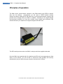
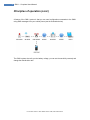
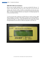
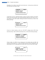
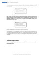
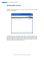
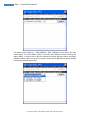
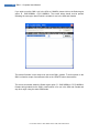
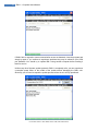
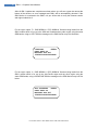
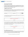
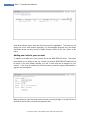
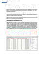
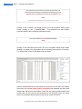
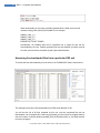
GML1 Owners Reference for use with the
AnaBat SD2 CF Bat Detector
Manual Version 1.46a, Modem Firmware Version V4R1 and SD2 Firmware Version 4061w
Revision Date 6th August 2012
This manual should be used with the SD2 User Manual v1.8 or later
1
GML1 – Complete Users Manual
TABLE OF CONTENTS
Section 1.
HARDWARE GUIDE...................................................................................... 2
Principles of operation ....................................................................................................... 3
Quick Start Notes – either system ..................................................................................... 5
Getting Started .................................................................................................................. 6
Configuring the Anabat SD2 CF Bat Detector ................................................................ 6
Checking the real time clock in Anabat SD2 CF Bat Detector ........................................ 6
Initialising the CF card ................................................................................................... 7
Recording some test data .............................................................................................. 7
Registering your new device .......................................................................................... 7
M2M DATA SIM Card Installation .................................................................................. 8
GML1 Configuration and Diagnostic Interrogation ............................................................. 9
Modem LED Indicators................................................................................................... 9
M2M data SIM Card Error .............................................................................................. 9
Carrier Error ................................................................................................................. 10
Carrier Network Detected............................................................................................. 10
Updating GML1 firmware ................................................................................................. 16
Technical specifications ................................................................................................... 21
Power supply requirements: ......................................................................................... 21
Power plug part numbers: ............................................................................................ 21
Antenna connectors ..................................................................................................... 21
RS232 cable: ............................................................................................................... 21
Section 2.
ONLINE USER INTERFACE........................................................................ 22
Accessing Your Data ....................................................................................................... 23
Logging into your account ............................................................................................ 23
The initial login report screen ....................................................................................... 23
Adding new units to your account ................................................................................ 24
Interrogating a particular SD2 unit ................................................................................ 25
Change the operating parameters of a particular SD2 unit ........................................... 26
Accessing the downloaded files from a particular SD2 unit .......................................... 31
For firmware versions – GML1 Modem version V4R1, SD2 version 4061w
2
GML1 – Complete Users Manual
Section 1. HARDWARE GUIDE
The GML1 system is a GPRS based self contained data acquisition and transfer module that
can be customized to fit almost any data logging device. The GML1 has a very low power
usage making it the perfect choice for battery operated installations. Wherever there is GSM
coverage the GML1 can be used to upload data from your data logging device to our central
server giving you not only convenient access to your data and remote monitoring facilities,
but also protecting your irretrievable data in catastrophic events such as the device being
stolen or damaged.
This manual is specifically written for applications where the GML1 is connected to, and
uploading data from an AnaBat SD2 CF Bat Detector system.
The instructions contained herein will take you through the entire processes necessary to
configure both the GML1 and the AnaBat systems so that they will operate in the most
effective manner possible.
These instructions are for use with an AnaBat SD2 CF Bat Detector system. This system will
be referred to as a ‘SD2’ system from here on.
For firmware versions – GML1 Modem version V4R1, SD2 version 4061w
3
GML1 – Complete Users Manual
Principles of operation
The GML1 device, pictured below, operates on the GSM network using GPRS to transfer
data over the Internet.
Consequently you will need a GPRS enabled wireless
machine-to-machine (M2M) DATA SIM card from a local telecommunication company that
provides such coverage where your GML1 is installed. Depending on the signal strength
(environmental conditions) you may also consider using a higher gain directional Yagi
external antenna if you experience low signal strength at the GML1 site.
The SD2’s serial port connects to the GML1’s serial port with the supplied serial cable.
Once the GML1 has transmitted all of the data from the SD2 unit to www.getmylog.com Web
Server on the Internet, you will be able to access this data (privately and securely
maintained as just your data) using any computer connected to the Internet.
For firmware versions – GML1 Modem version V4R1, SD2 version 4061w
4
GML1 – Complete Users Manual
Principles of operation (cont.)
A feature of the GML1 system is that you can send configuration commands to the GML1
using SMS messages from your mobile phone (see the illustration below).
The GML1 system also tells you the battery voltage, you can set the sensitivity remotely and
change the data division ratio.
For firmware versions – GML1 Modem version V4R1, SD2 version 4061w
5
GML1 – Complete Users Manual
Quick Start Notes – either system
The following steps summarize the necessary steps required to get the GML1 up and
running. For those of you who are new to the GML1, or who like detailed explanations,
please refer to subsequent sections of this manual for very detailed explanations of the
following steps. Note, however, that once you have followed the rest of the manual, you
should none-the-less refer back here to verify that you have not missed or glossed over
anything important.
1.
Setup the software on your computer/laptop
2.
Have a USB / Serial Port available for communications with the SD2
3.
Have a Compact Flash reader / writer device connected and functioning
4.
Program the SD2 4061w firmware into the SD2
5.
Configure a Compact Flash (CF) memory card for the initial testing
6.
Record some data onto the CF card for the initial testing
7.
*Obtain a compatible M2M data SIM card for your area
8.
Connect all cables to the GML1 and SD2
9.
Ensure you have a compatible antenna connected to the GML1 unit
10. Connect the GML Monitor to the GML1 to enable debugging
11. Log into www.getmylog.com with your account details provided and use the
‘NEW DEVICE’ feature to add the serial number of the SD2 device to your
account as per page 22 of this manual. Failure to do this will cause an
unsuccessful connection to the getmylog server
12. Power on the GML1 unit
13. Send an SMS to configure the M2M data SIM card
14. Once the GML1 is configured and waiting for the SD2, power on the SD2
15. Check the GML1 monitor for the progress of transfer of data to the server
16. Once completed, log on to the server and check and download the transferred
data
17. Disconnect the GML Monitor
* Step 7 is the most difficult step. Note that you have to have an M2M DATA SIM Card. It is
essential that first time users refer to the website for further details relevant to your region to
source a compatible M2M DATA SIM Card. Pre-configured M2M DATA SIM Cards may be
available at time of purchase.
For firmware versions – GML1 Modem version V4R1, SD2 version 4061w
6
GML1 – Complete Users Manual
Getting Started
Firstly you need to verify that the location where the GML1 will reside has suitable GSM
network coverage and source an appropriate GSM M2M DATA SIM card. Please note that
some providers seem to have limitations on how much data can be uploaded (continuously)
over the GPRS network (such as the prepaid Optus M2M DATA SIM cards in Australia). It is
strongly recommended that you investigate all options available from all providers in the
region and to choose the plan which has the least number of limitations on the transfer of
data (in both directions). Cost is not always the best discriminator in these situations. If in
doubt, just remember to ask the provider if the plan will allow you to upload at full speed
around 20 Mbytes of data in, say, an 10 hour period without resetting or terminating the
connection at set intervals (be such intervals data blocks or time segments).
Configuring the Anabat SD2 CF Bat Detector
The data recorded by an SD2 is stored on a configured Compact Flash memory card
(referred to as the CF here on) in the SD2. The SD2 unit needs special firmware in order to
communicate with the GML1 unit.
See the SD2 User Manual for ‘HOW TO UPGRADE THE FIRMWARE’.
The relevant firmware version for the SD2 is currently version 4061w, the ‘w’ implies the
wireless GML1 version of the SD2 firmware.
Checking the real time clock in Anabat SD2 CF Bat Detector
Once the firmware has been upgraded it is a good idea to check for the correct time in the
SD2. This is because the time zone where the system is being deployed may well be
different to the time zone at the place of manufacture.
See the SD2 User Manual for ‘HOW TO CHECK AND SET THE REAL TIME CLOCK IN
THE SD2’.
Please note that when you use CFCread to set the SD2 time it will be set to the date and
time of the computer it is connected to. Consequently make sure the computer has the
correct date and time set for the time zone that the GML1 will operate in.
For firmware versions – GML1 Modem version V4R1, SD2 version 4061w
7
GML1 – Complete Users Manual
Initialising the CF card
As mentioned above, the Compact Flash Card is referred to as CF in the following
instructions.
See the SD2 User Manual for ‘FORMATTING CF CARDS’ and ‘HOW TO INITIALISE CF
CARDS’.
Recording some test data
For a test ONLY, using the CFCread program set the ‘Monitoring begins at ...’ time to be say
½ hour from the current time and ‘Monitoring ends at ...’ time to be say 1 hour from the
current time. This will give a ½ hour recording window (starting from the current time) to
store data onto the CF card for a test of the transfer system.
Left click on the ‘Erase’ button, this will store the programmed recording times onto the CF
card for use in the SD2. The CFCread program should indicate ‘Disk Erased to Sector 1’.
Remove the CF card from the CF reader / writer and insert the CF card into the SD2 while it
is powered off.
Power on the SD2 and the ‘Standby’ LED should light for approx 120 seconds before the
SD2 powers off. The SD2 is now waiting for the programmed ‘Monitoring begins at ...’ time
to wake up and start recording.
At the ‘Monitoring ends at ...’ time after a further 120 seconds, the SD2 will shutoff waiting for
the next day’s ‘Monitoring begins at ...’ time to recommence the recording cycle again.
For this test at this point the CF card has data to transfer and the SD2 is now ready to
connect to the GML1 system to transfer data to the server using the GSM GPRS mobile
phone network.
Registering your new device
For the getmylog server to recognise your SD2 device, you must log into www.getylog.com
with your account details provided, and use the ‘NEW DEVICE’ feature to add the serial
number of the SD2 device to your account as per page 22 of this manual. Failure to do this
will cause an unsuccessful connection to the getmylog server.
For firmware versions – GML1 Modem version V4R1, SD2 version 4061w
8
GML1 – Complete Users Manual
M2M DATA SIM Card Installation
Make sure that the GML1 is powered down. Now insert the M2M DATA SIM card. To
release or insert a M2M DATA SIM card you need to gently slide it into the slot (see the
drawing on the side panel of GML1 for details on card orientation) and then press onto it
gently, but firmly, until you hear a click sound. Once clicked in the card will be locked inside
GML1. (To release the M2M DATA SIM card you simply push on its leading edge again and
it will unlock and eject smoothly.)
To move to the next step in setting up your GML1 device you need to connect a digital
display interrogation unit (called the GML Monitor and shown in the following diagram) to
complete initialization of the device. Plug the GML MONITOR cable into the GML1 AUX port
and power up the GML1 unit. Wait a brief period for the device to respond and then follow
the steps described in the next section to finalize the configuration of your GML1 unit.
For firmware versions – GML1 Modem version V4R1, SD2 version 4061w
9
GML1 – Complete Users Manual
GML1 Configuration and Diagnostic Interrogation
After connecting the GML Monitor and powering up the GML1, you should see the following
“WAITING FOR DEVICE” message displayed on the Monitor screen.
GETMYLOG MONITOR
Version 1.1 R2
WAITING FOR DEVICE
If you freeze on this screen then check that you are connected to the SD2 and that the
correct firmware has been loaded on both devices. Please email support if you need any
further assistance.
Modem LED Indicators
When power is first applied to the modem, the RED ‘STATUS’ LED on the modem end panel
flashes intermittently. The GREEN ‘PWR’ LED is not a POWER indication LED. It is driven
by firmware inside the modem and is not lit initially, but lights after approximately 25 to 35
seconds from when power is applied to the modem.
M2M data SIM Card Error
If the GML1 cannot access your M2M data SIM card, or your M2M data SIM card is locked,
you will see the following “SIM CARD ERROR” screen.
SIM CARD ERROR
NOT READY OR LOCKED
358280004082992V4R1D
The 15 digit on the bottom line of the display is the IMEI number of the GML1 modem and is
followed by the firmware version in the modem, this and the following screen shots are
an example where an AT&T SIM is used with V4R1D firmware loaded for GML1 use in
the USA or Canada and any other region using the same GSM bands.
You can use a mobile phone to remove the M2M data SIM card lock and verify that the card
is working.
A typical menu input to disable the SIM PIN is as follows, this will vary between mobile
phones though.
Enter the menu system using the following path (Settings>Phone>SIM PIN>off) to disable
the SIM PIN lock.
For firmware versions – GML1 Modem version V4R1, SD2 version 4061w
10
GML1 – Complete Users Manual
Carrier Error
If your M2M data SIM card cannot find any networks to register you will see “Carrier not
found” instead as shown below.
CARRIER NOT FOUND
358280004082992V4R1D
Carrier Network Detected
If a valid service provider can be found (there is enough signal to connect to the GSM
network supported by your M2M data SIM card) you will see the name of the network and its
signal strength. If the GML1 was able to find a carrier it will give you an indication of its
signal strength in dBm.
You should position your antenna to achieve a signal of no less than -91 dBm (a signal of 95 dBm for example is a LOWER level signal then -91 dBm, a signal of -84 dBm for example
is a STRONGER level signal then -91 dBm). Most (but possibly not all) service providers
send signals such that the antenna should be pointing in a vertical orientation for the
strongest signal. Contact Titley Scientific if you need assistance at any stage.
GML1 will continue to operate at lower signal strengths however the transmission speed and
stability of GPRS link may be adversely affected.
CINGULAR
-88dbm
GPRS TEST ERROR
WAITING FOR CONFIG
358280004082992V4R1D
NOTE – The SIM card must have the access point name ‘Internet’ assigned to it by the
network service provider of the SIM card. If this has not been done the SIM card will
not connect to the Internet and will leave the system sitting at the error condition
above.
As soon as a carrier is found the unit will commence a GPRS test. If a GPRS connection
cannot be established then it will wait for a valid configuration to be set. To do this, you
need to provide the following details for your GPRS connection:
access point name, user name, password
This is easily done using any mobile phone to send the following SMS message to your
GML1 unit phone number.
For firmware versions – GML1 Modem version V4R1, SD2 version 4061w
11
GML1 – Complete Users Manual
NOTE – The word ‘conf’ MUST be in lower case letters otherwise the configuration
message will not be processed by the modem firmware correctly.
This message only has to be sent once when setting up the GML1 system, or whenever you
change the SIM card in the GML1 to use a SIM card from another service provider that has
not been sent the configuration message in the format below.
conf,access point name,user name,password
For the region option ‘D - GMS 850MHz + PCS 1900MHz’ firmware being loaded into the
GML1 modem which is for use in the USA and Canada and any other region using the same
GSM bands, using an AT&T SIM configuration SMS would look like this:
conf,isp.cingular
Please note that many providers in Australia require only the access point name, which is
usually “internet”. Thus in Australia your M2M data simple configuration SMS would look like
this:
conf,internet
After you send the SMS you will need to wait for the GML1 to process the new configuration
SMS and pass the initial GPRS test (please note that there may be delays, sometimes many
minutes, in SMS communication if the GML1 is connected to a different provider than the
mobile phone you are sending the SMS from). You may send the SMS configuration
multiple times, however only the latest SMS will be used by the GML1 device.
If you have purchased your own SIM Card, then you may have to discuss any issues you
have (at this point) with the service provider.
CINGULAR
-88dbm
AP: isp.cingular
TESTING GPRS
358280004082992V4R1D
After the initial GPRS test is successfully completed, GML1 will complete its boot sequence
and switch to operational mode. If your SD2 is busy recording or not connected you will see
the following “WAITING FOR SD1” message.
CINGULAR
-88dbm
GPRS TEST OK
WAITING FOR SD1
358280004082992V4R1D
For firmware versions – GML1 Modem version V4R1, SD2 version 4061w
12
GML1 – Complete Users Manual
When your SD2 unit enters Standby mode and has data stored on its CF memory card the
GML1 will contact the server to download the latest device settings. If your SD2 unit is
registered on the server you will see the “SETTINGS RECEIVED” message as below.
CINGULAR
-88dbm
DOWNLOAD SETTINGS
SETTINGS RECEIVED
358280004082992V4R1D
If your SD2 unit is not registered or the server cannot be accessed you will see the
“SERVER NO RESPONSE” message. To fix this error, you will need to ensure that your
SD2 unit is registered on our server.
CINGULAR
-88dbm
DOWNLOAD SETTINGS
SERVER NO RESPONSE
358280004082992V4R1D
After the latest settings are downloaded, the GML1 will send reports to the server and to the
specified mobile phone by SMS.
CINGULAR
-88dbm
SENDING SMS
SMS FAILED
358280004082992V4R1D
If you requested an SMS report the following message will be sent to the specified mobile
phone. (If your M2M data SIM card does not allow SMS messages to be sent you will see a
“SMS FAILED” message above.)
The SMS will be in the form - SN:”Serial number”-“Stored data in kb”kb, BT:”Battery
voltage”V, SE:”Sensitivity value”, DR:”Data division ratio” ,CS:”Chunk size in kb”kb
For firmware versions – GML1 Modem version V4R1, SD2 version 4061w
13
GML1 – Complete Users Manual
Regardless of your setting, a report will be sent to the server. In this report you will also see
if the SMS report succeeded or failed.
CINGULAR
-88dbm
SENDING REPORT
REPORT FAILED
358280004082992V4R1D
If report fails you will see a “REPORT FAILED” message, otherwise the GML1 will remember
the time of the last successful report and wait another day before the next report is sent. If
you selected to only receive reports, leaving all the data on the device, you will see the
following message.
CINGULAR
-88dbm
SENDING REPORT
REPORT ONLY
358280004082992V4R1D
If there is no data to upload you will see a “NO DATA” message and the SD2 will be
instructed to sleep. When the SD2 enters sleep mode, you will see the following message:
CINGULAR
-88dbm
DOWNLOAD SETTINGS
SHOULD BE ASLEEP
358280004082992V4R1D
If there is data on the GML1 and you selected one of the upload modes, the GML1 will
contact the data storage server. If either the GPRS connection cannot be established or the
data storage server is not responding, then the GML1 will wait a few seconds and try again.
CINGULAR
-88dbm
STARTING UPLOAD
DATA: 1622 kb
358280004082992V4R1D
For firmware versions – GML1 Modem version V4R1, SD2 version 4061w
14
GML1 – Complete Users Manual
The “BLOCK” message below indicates that data blocks are being sent to the storage
server. Note that you will not be able to see upload progress of individual blocks on your
GML Monitor, but you can see it on the getmylog.com website.
CINGULAR
-88dbm
BLOCK 1 OF 2
DATA: 1622 kb
358280004082992V4R1D
When GML1 moves to another block it will display the last block number that was
successfully uploaded.
CINGULAR
-88dbm
BLOCK 2 OF 2
BLOCK 1 SENT
358280004082992V4R1D
If GML1 experiences any problems with SD2 connection the message “SD1R ERROR” will
be displayed and next attempt will be executed shortly.
CINGULAR
-88dbm
ERROR DETECTED
SD1R ERROR - RETRY
358280004082992V4R1D
If GML1 experiences any problems with either: GPRS, Internet or Server connection, the
message “SRVT ERROR” will be displayed and next attempt will be executed shortly.
CINGULAR
-88dbm
ERROR DETECTED
SRVT ERROR - RETRY
358280004082992V4R1D
For firmware versions – GML1 Modem version V4R1, SD2 version 4061w
15
GML1 – Complete Users Manual
If the data upload is successfully completed, GML1 will erase the data stored on the CF
card in the SD2.
CINGULAR
-88dbm
UPLOAD COMPLETED
ERASING SD1:12345
358280004082992V4R1D
GML1 will also send a file assembly request after all blocks are successfully uploaded. If this
request fails you will see an “ASSEMBLY FAILED” message and the file set will continue to
appear as “INCOMPLETE” in your file list. This request will be repeated multiple times in
case of communication failure.
CINGULAR
-88dbm
UPLOAD COMPLETED
ASSEMBLY FAILED
358280004082992V4R1D
PLEASE REMEMBER TO DISCONNECT THE GML MONITOR!
The GML Monitor is a vital diagnostic tool but it is not required for GML1 to operate. It also
consumes more power than an idle GML1 unit. The GML Monitor should only be used to set
up the GML1 unit and for initial testing. It is not designed to be permanently connected to
your GML1.
Accessing your data
You can access your data on the getmylog.com website. This is covered in the second
section of this manual.
For firmware versions – GML1 Modem version V4R1, SD2 version 4061w
16
GML1 – Complete Users Manual
Updating GML1 firmware
The GML1 V4R1 Update Utility is a single EXE firmware update program designed
specifically for GML1 devices.
To program the firmware in the modem connect the GML1 unit to a spare serial port on your
computer (you may use a USB to RS232 converter cable). After you run the V4R1 program
and select the COM port from the drop down list please make sure that GML1 is powered
down before clicking on the CONNECT button. In the example below COM1 port has been
selected as the serial port connected to the GML1 unit.
For firmware versions – GML1 Modem version V4R1, SD2 version 4061w
17
GML1 – Complete Users Manual
The default region setting (A – GSM 900MHz + DCS 1800MHz) is that used in the Asia
Pacific region. To use the GML1 system in the USA and Canada you need to change the
region setting. To do this click on the blue selection tick at the right hand side of the region
indication window. When you do this a selection screen will be displayed as below showing
the currently selected region code.
For firmware versions – GML1 Modem version V4R1, SD2 version 4061w
18
GML1 – Complete Users Manual
If you wish to use this GML1 unit in the USA or CANADA, please click on the Select region
option ‘D - GMS 850MHz + PCS 1900MHz’. The screen below should now be present
indicating the new region band D which is suitable for use in the USA and Canada.
The modem firmware is now ready to be sent to the GML1 modem. To do this power on the
GML1 unit wait a couple of seconds and click on the UPDATE button shown above.
The screen shot below shows the Select region option ‘D - GMS 850MHz + PCS 1900MHz’
firmware being loaded into the GML1 modem which is for use in the USA and Canada and
any other region using the same GSM bands.
For firmware versions – GML1 Modem version V4R1, SD2 version 4061w
19
GML1 – Complete Users Manual
If GML1 fails to respond or some communication errors are detected, close the program and
simply try again. If you continue to experience problems they may be related to your COM
port hardware. You should try to update GML1 using another computer before sending it
back for service.
Unlike many other firmware update protocols GML1 is completely safe, you can experience
a complete power failure in the middle of the update without damaging the GML1 unit.
Obviously you will need to repeat the update process before the unit is fully operational.
For firmware versions – GML1 Modem version V4R1, SD2 version 4061w
20
GML1 – Complete Users Manual
After all GML1 updates are completes as shown above you will see a green bar across the
bottom of the window, no error messages and GML1 will be automatically rebooted. If the
GML Monitor is connected to the GML1 unit you will be able to verify the firmware version
and region loaded into it.
For the region option ‘D - GMS 850MHz + PCS 1900MHz’ firmware being loaded into the
GML1 modem which is for use in the USA and Canada and any other region using the same
GSM bands, using an AT&T SIM the message on the GML Monitor may look like below.
CINGULAR
-88dbm
GPRS TEST OK
WAITING FOR SD1
358280004082992V4R1D
For the region option ‘A - GMS 900MHz + DCS 1800MHz’ firmware being loaded into the
GML1 modem which is for use in the Asia Pacific region and any other region using the
same GSM bands, using a VODAFONE SIM the message on the GML Monitor may look like
below.
AUS VODAFONE -88dbm
GPRS TEST OK
WAITING FOR SD1
358280004082992V4R1A
For firmware versions – GML1 Modem version V4R1, SD2 version 4061w
21
GML1 – Complete Users Manual
Technical specifications
Power supply requirements:
8-24V
24V , 12mA @ idle without the GML1 monitor (22mA with the monitor attached and
backlight OFF, 110mA with the backlight ON), 150mA @ 2W output (all testing was
conducted on a 12V power supply)
pply)
Power plug part numbers:
-Molex
Molex 4 pin female connector (part no: 43025-0400)
43025
-Molex
Molex female tin plated crimp terminals (part no: 43030-0001)
43030
See the drawing above for polarity (note only 2 pins need to be connected)
Included in the distribution
on CD is a wiring diagram GML System Power Wiring.pdf which
details the wiring for a 2 wire and 4 wire power cable. The 4 wire moulded cable has 2 wires
which are not used for the GML system at present.
Antenna connectors
You will need a quad-band
band GSM antenna
antenna with a SMA Male connector (note some antennas
sourced in Australia are only dual-band
dual band and may not be suitable for use in the USA or
CANADA). In some remote areas you may need to purchase a high gain antenna. Although
more expensive than the smaller ones
ones (that work OK in regional areas), the high gain
antennae are especially suitable in remote and rural areas as well as in certain
environmental setups (for example, in a deep gully in the outback surrounded by high iron
ore bearing cliff faces).
RS232 cable:
The SD2’s serial port connects to the GML1’s serial port with the supplied serial cable.
For firmware versions – GML1 Modem version V4R1, SD2 version 4061w
22
GML1 – Complete Users Manual
Section 2. ONLINE USER INTERFACE
This section introduces you to the management of your online data. It takes you through the
steps to log onto the server and then how to download the data from the server to your local
PC.
Note this interface was designed to be as simple as possible, with maximum automation
behind the scenes. Consequently the information and screens displayed are easy to
navigate and manipulate. It typically takes only a few minutes to familiarize yourself with the
operations available to you on the Web.
For firmware versions – GML1 Modem version V4R1, SD2 version 4061w
23
GML1 – Complete Users Manual
Accessing Your Data
The data from your SD2 will be uploaded to the server as described in the previous section.
Naturally you will want to access that data, your data, at appropriate intervals or, quite often
just check on the status of the dataset that has accumulated on the server. The first step to
gaining access to the uploaded SD2 data is to log in.
Logging into your account
When you received your GML1 hardware, you would have been supplied with a user name
and password for your account. Start by going to the getmylog.com website and entering
your user name and password into the following screen:
If you made a mistake, then the following message will appear. Simply click on the Try Again
button to repeat the login process.
If you have entered the correct username and password, but get the following message,
then your account has been suspended. In this case you will need to contact the GML
system administrator to determine the reason. Only the system administrator can activate
your account once it has been suspended.
The initial login report screen
After login you will see the following screen. This screen shows reports that cover the last
24 hours. Each report is for one of the SD2 units registered on your account. Thus these
reports cover all activity across all the SD2 units associated with this login.
For firmware versions – GML1 Modem version V4R1, SD2 version 4061w
24
GML1 – Complete Users Manual
Units which failed to report within the last 24 hours will be highlighted. To access any unit
simply click on its serial number (hyperlink). For demonstration purposes only, the screen
shot above shows an early version of GML1 firmware (V3R3) in the ‘Ver’ column of the
report.
Adding new units to your account
To register a new SD2 unit to your account click on the ‘NEW DEVICE’ button. This screen
below allows you to register a new unit. Please note that the ‘NEW DEVICE’ button will not
be active if you have already reached your limit of units that can be assigned to your
account. If you need to increase this limit then please contact the system administrator to
upgrade your subscription.
Make sure that you enter the serial number correctly including all digits. If not the SD2 unit in
the field will not be able to connect and upload it’s data.
For firmware versions – GML1 Modem version V4R1, SD2 version 4061w
25
GML1 – Complete Users Manual
To allow for the correct maintenance of historical data, please note carefully that this
operation (of adding a new SD2 unit) can not be undone. Once you have created the new
device, you will not be able to de-register this unit from your account. So, again, please
ensure that you have entered all data correctly and verify each and every field entered
before creating the device. The GML administrator can however transfer serial numbers from
one user account to another user account in the case that the SD2 has been sold or
transferred to another user.
If the server detects any problems with the registration information entered, then you will see
an error message explaining which fields are not filled out correctly. Please note that this is
not a perfect error detection system and thus, as above, you are ultimately responsible for
entering the correct data into the correct fields.
Immediately after you register your new device it will appear in the devices list and your SD2
unit in the field will be able to start uploading data.
Interrogating a particular SD2 unit
After logging in, on the Recent activity report screen shown previously, click on the Serial
Number of the SD2 you wish to view and you will see the Complete activity report showing
the last 100 reports received from this GML1. The operating parameters read from the SD2
are shown in fields labelled - Data is in Kb, Battery in Volts, Div is Data Division Ratio either
16, 8 or 4. Sens is Sensitivity as a percentage from 0 to 100. SMS Phone is self explanatory,
Chunk Size in multiplication of 512 bytes. For demonstration purposes only, the screen shot
below shows an early version (V3R3) of GML1 firmware in the ‘Ver’ column of the report.
NOTE - Modem firmware version V4R0/U and later – the Date & Time shown on all the
report screens is now the date and time from the SD2 unit connected to GML1, so the
report now displays the local date and time of the SD2 unit when the GML1 contacted
the server. Previous versions (V3R8/U and earlier) displayed the date and time at the
server (GMT+10) when the GML1 contacted the server. Any downloaded files are
named using the date and time from the SD2 unit connected to GML1.
For firmware versions – GML1 Modem version V4R1, SD2 version 4061w
26
GML1 – Complete Users Manual
Change the operating parameters of a particular SD2 unit
If you wish to change the settings for this unit fill out the above form on the right side and
when all the required parameter changes are done, click the ‘Update’ button.
You will see the result of your request displayed below the ‘Update’ button. This action will
transfer the new parameters to the GML1 next time it contacts the server.
There are 8 parameters that can be controlled by the user and these are detailed below,
each parameter has a number of settings available.
1.
‘Mode’
Each of the modes below takes effect at the end of the next SD2 recording session.
a. Report Only – tells the GML1 to ONLY send a report to the getmylog.com
server, no upload of data occurs, no SMS is sent.
b. Report + Upload – tells the GML1 to send a report to the getmylog.com
server and upload any recorded data, no SMS is sent.
c. Report + SMS – tells the GML1 to send a report to the getmylog.com server
AND an SMS to the mobile phone number appearing in the ‘Send SMS to’
selection window, no upload of data occurs.
d. Report + Upload + SMS – tells the GML1 to send a report to the
getmylog.com server AND an SMS to the mobile phone number appearing in
the ‘Send SMS to’ selection window. The GML1 will also upload any recorded
data.
2. ‘Suspended’
When an SD2 device is not connected to a GML1, it is best to change the status of
the SD2 to Suspended.
If you tick the ‘Suspended’ check box, the SD2 serial number will appear in the list of
devices in the ‘Suspended’ section of the Recent activity report page.
Suspended status prevents the SD2 serial number appearing in the list of devices in
the ‘No report from’ section of the Recent activity report page.
Any devices listed in the ‘No report from’ section of the Recent activity report page
are assumed to be Active but have not contacted the server within the last 24 hours,
so these devices should be checked. This method is used as a ‘heartbeat’ indicator
to tell you the operational status of each GML1 unit on a daily basis.
3. ‘Send SMS to’
Enter the mobile phone number that you wish to send an SMS report to (if that
operating mode is selected). Note use only numerals and don’t include any spaces or
hyphens.
For firmware versions – GML1 Modem version V4R1, SD2 version 4061w
27
GML1 – Complete Users Manual
4. ‘Division Ratio’
The Data division ratio controls the resolution and thus the amount of data for a given
recorded call. There are 3 available Data Division ratios, 16, 8 and 4
A Data division ratio of 4 provides finer resolution in the call than 16 but requires four
times as much data to store the same call
A Data division ratio of 4 is best used for lower frequency calls or sites where you
don’t get large amounts of data which may prevent the system from uploading a
complete night’s recording the following day
5. ‘Sensitivity’
The SD2 uses a Sensitivity control to optimise the recording of calls.
If this control is set too high then electronic static, undesired noise from the wind,
insects or other forms of ultrasonic noise will be recorded, leading to a large data file
being uploaded to the server. Large data files can prevent a single night’s recording
session being sent to the server the following day, possibly taking multiple days
according to the size of the data file.
If this control is set too low then you risk not detecting the available bat calls within
range of the SD2.
The value entered into the Sensitivity selection window on the Complete activity
report controls 2 modes of operation of the SD2 Sensitivity function.
a. A value of 0 (‘Manual’ mode) tells the SD2 to use its own front panel Sensitivity
control.
In this 0 = ‘Manual’ mode, the value reported in the ‘Sens’ column of the
Complete activity report represents the mechanical position of the SD2 front
panel Sensitivity control, where 1 represents the minimum Sensitivity value ie.
0% (fully counter clockwise) and 9 is the maximum Sensitivity value ie. 100%
(fully clockwise).
Note - at a Sensitivity value of 100% the SD2 would produce a lot of data due to
detecting electronic static and should never be used at this setting.
b. Any other value of 1 to 100 (‘Server’ mode) tells the SD2 to use this 1 to 100
value ignoring the SD2’s own front panel Sensitivity control. This function thus
gives you remote control of the SD2 Sensitivity control.
In ‘Server’ mode the value entered into the Sensitivity selection window on the
Complete activity report represents a percentage from 1% to 100%, where 1% is
the minimum Sensitivity value and 100% is the maximum Sensitivity value.
The ‘Server’ mode value (1 to 100) will also appear in the ‘Sens’ column of the
Complete activity report.
For firmware versions – GML1 Modem version V4R1, SD2 version 4061w
28
GML1 – Complete Users Manual
Note - at a Sensitivity value of 100% the SD2 would produce a lot of data due to
detecting electronic static and should never be used at this setting.
Any ‘Server’ mode Sensitivity value should only be set by an expert user who has
prior familiarity with the Sensitivity setting.
Sensitivity conversion table
As a guide to how the scale on the SD2 front panel Sensitivity control converts to a
percentage the following table may assist you. Please note there will be minor
manufacturing variations between SD2 units that may lead to a slight variation of the
numbers used on your particular SD2 unit.
The GML1 V4R1 firmware converts the mechanical position of the front panel
SENSITIVITY scale (1 to 9) to a number between 0 and 100.
The table below is an approximation of the scale value displayed or entered to
control the function, converting mechanical position to percentage using a logarithmic
correction curve.
Label setting
Sensitivity as a percentage in 0% to 100% range
1
1
2
3
3
7
4
15
5
22
6
29
7
59
8
87
9
100
As an example you may see a value of 59% displayed in the Sens column on the
Complete activity report. This approximates to a setting of around 7 on the front
panel Sensitivity control
Use the table above should you wish to remotely control the SENSITIVITY function of
the SD2.
6. ‘Chunk Size’
This value is multiplied by 512 bytes to determine the size of the individual parts that
a large data file is uploaded to the server. It is recommended for now that the value in
this selection window be left at 1953, the default value. Too smaller value will
increase the time taken to upload a complete data file, so please consult with Titley
Scientific before altering this value. It is used to optimise the upload performance and
should not be altered unnecessarily.
For firmware versions – GML1 Modem version V4R1, SD2 version 4061w
29
GML1 – Complete Users Manual
7. ‘Update’
The ‘Update’ function is used to transfer any new parameters to the GML1 next time
it contacts the server.
When all the required parameter changes are done, click the ‘Update’ button.
You will see the result of your request displayed below the ‘Update’ button.
8. ‘Delete Data’
This is a new function only available with GML firmware versions V4R0/U and later.
This function is used to correct situations where excessive data has been recorded
due to external influences or incorrect setup values and allows the GML system to
erase the large data file from the CF card in the SD2 without having to upload the
data file to the server.
A large data file, for example 200MB of data may take several days to upload and if
the information in the data file is useless because of recording or environmental
conditions, then you may wish to not upload this data set.
You must exercise extreme caution if you elect to use the ‘Delete Data’
function as outlined below. This is a non recoverable procedure and if you
proceed with this function your data will be erased from the CF card in the SD2
To delete all data on a device click on the ‘Delete Data’ button on the bottom RHS.
A confirmation screen as shown below will appear explaining the consequences and
firmware requirements. If the ‘Delete Data’ function is used on GML1 firmware
V3R8/U or earlier, it will have no effect on the device. A ‘Data deletion scheduled’
message will still appear on the device screen until the current file is completed and
then it will disappear.
For firmware versions – GML1 Modem version V4R1, SD2 version 4061w
30
GML1 – Complete Users Manual
Clicking on the ‘CANCEL’ text brings returns you to the Complete activity report
screen. Clicking on the ‘I UNDERSTAND ..’ link schedules the data deletion
procedure and brings the following confirmation screen.
Clicking on the ‘RETURN’ text returns you to the Complete activity report screen
showing a red label in the right bottom corner indicating ‘Data deletion scheduled’.
The ‘Delete Data’ button will be hidden as shown below.
After the scheduled delete is executed (which is the next time the GML unit contacts
the server) the red label (Data deletion scheduled) will disappear and the button
‘Delete Data’ will become visible again. If there are any partial uploads related to the
deleted data file they will now be accessible on the download screen as shown
below. As an example Device 04446 is used for the screen shot below.
For firmware versions – GML1 Modem version V4R1, SD2 version 4061w
31
GML1 – Complete Users Manual
When downloading or removing a partially uploaded file the GML server will still
indicate missing parts (chunks) of the data file, for example:
090822_1429_1_4
090822_1429_2_4
090822_1429_3_4
ERROR PART 4 NOT FOUND
Nonetheless, all available data will be combined into a single file that can be
downloaded by the user. Partially uploaded files are also backed up before removal
from the server and thus accessible by the System Administrator.
Accessing the downloaded files from a particular SD2 unit
To access the files downloaded by this unit click on the ‘DOWNLOAD’ button shown below.
The examples below show files downloaded from SD2 Serial Number 01181
You will see the list of all files uploaded by this unit, only the completed files can be
downloaded. If an Incomplete file is still being uploaded you can monitor its progress both by
size and number of chunks already uploaded (click the Refresh button on your Web browser
to see any changes).
For firmware versions – GML1 Modem version V4R1, SD2 version 4061w
32
GML1 – Complete Users Manual
Click on the File name required to start the download process.
The example below shows a multi chunk download from SD2 01181 which finished
recording at 11:30AM 2nd July 2009.
All of the chunks of the selected data file will be automatically assembled into a single file
that you can download by clicking on the ‘DOWNLOAD ..’ text on the above screen and you
will be presented with another Windows screen as below.
Click on the ‘Save’ button and another Windows screen will present itself as below.
For firmware versions – GML1 Modem version V4R1, SD2 version 4061w
33
GML1 – Complete Users Manual
Navigate to the folder you wish to save the download file and then click the ‘Save’ button, the
example above will save the data file to a folder ‘Bat Files’.
Once the download is complete, you will return to the screen below.
Click on the ‘RETURN’ text to take you back to the list of files available for download as
below.
For firmware versions – GML1 Modem version V4R1, SD2 version 4061w
34
GML1 – Complete Users Manual
If you wish to delete any files listed click on the ‘Remove’ text associated with the selected
file to delete and the following confirmation screen will appear. Please note that once file is
deleted from the server it is gone forever.
You can return to the previous screen as shown below by clicking on the ‘RETURN’ text.
You will notice that the file 090629_1540 now does not appear in the list of files available for
download.
You can return to the Complete activity report screen as shown below by clicking on the
‘RETURN’ text.
Clicking on the ‘LOG OUT’ button terminates your connection with the getmylog.com server.
For firmware versions – GML1 Modem version V4R1, SD2 version 4061w


![Roostloggers [Titley] - An Introductory Manual](http://vs1.manualzilla.com/store/data/005649014_1-8c618e497bb2550a491bca85d50a292e-150x150.png)