1
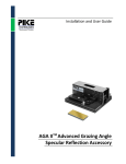
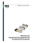
Installation and User Guide
XY Autosampler Diffuse Reflectance
and Transmission Accessory
The information in this publication is provided for reference only. All
information contained in this publication is believed to be correct and
complete. PIKE Technologies, Inc. shall not be liable for errors contained herein
nor for incidental or consequential damages in connection with the furnishing,
performance, or use of this material. All product specifications, as well as the
information contained in this publication, are subject to change without notice.
This publication may contain or reference information and products protected
by copyrights or patents and does not convey any license under the patent
rights of PIKE Technologies, Inc. nor the rights of others. PIKE Technologies, Inc.
does not assume any liability arising out of any infringements of patents or
other rights of third parties.
This document contains confidential or proprietary information of PIKE
Technologies, Inc. Neither this document nor the information herein is to be
reproduced, distributed, used or disclosed, either in whole or in part, except as
specifically authorized by PIKE Technologies, Inc.
PIKE Technologies, Inc. makes no warranty of any kind with regard to this
material including, but not limited to, the implied warranties of merchantability
and fitness for a particular purpose.
Copyright 1991-2013 by PIKE Technologies, Inc., Madison, WI 53719. Printed in
the United States of America. All world rights reserved. No part of this
publication may be stored in a retrieval system, transmitted, or reproduced in
any way, including but not limited to, photocopy, photograph, magnetic or
other record, without the prior written permission of PIKE Technologies, Inc.
Address Comments to:
PIKE Technologies, Inc.
6125 Cottonwood Drive
Madison, WI 53719
Phone
Fax
E-mail
Web Site
Jan. 1, 2013
(608) 274-2721
(608) 274-0103
[email protected]
www.piketech.com
Contents
Introduction
Unpacking Your Accessory
Packing List
Optical Description
Installation
Mounting the Accessory
Connecting the DTGS Detector
Connecting to your Computer
Powering-Up the Accessory
Accessory Sampling Plates
Accessory Alignment
Precautions - Mirrors
PN 350-047000-01
1
2
2
3
4
4
5
5
5
5
6
6
P a g e |3
Introduction
The X, Y Autosampler is designed around standard 96-well microplate architecture. It features an X, Y
stage with both axes driven by precision servo motor/leadscrew combinations and is available in four
different configurations:
•
•
Mid-IR Diffuse Reflectance
Mid-IR Diffuse Reflectance/Transmission
•
•
NIR Diffuse Reflectance
NIR Diffuse Reflectance/Transmission
The transmission version has an IR transparent tray and a built-in DTGS detector mounted inside the
accessory.
Table 1. Specifications
Optics
Sample spot size
Angle of Incidence
Mechanical Specifications
Repeatability
Resolution
Mechanical Range of Motion
Sampling Range of Travel
Minimum Run Time
Computer Interface
Dimensions (W x D x H)
Weight
3X beam de-magnification from spectrometer sample focus
30°
+/- 5 μm
1 μm
63 mm x 250 mm (in unloaded position)
63 mm x 99 mm
56 seconds for 96-well plate (actual time is spectrometer
and application dependent)
USB
5.55 x 13.2 x 6.25" (including micrometer)
10 lbs
The optical design is based on a precision ellipsoidal reflector and the size of the spot illuminated at the
sample is approximately 2 mm (the final beam size is spectrometer dependent).
Two types of sampling plates are offered in the 96-well configuration. The reflectance sampling plate
contains 96 wells in an 85 mm x 125 mm rectangular grid. These wells are 7 mm diameter and 5 mm
deep, and may be used to hold polymer beads, powders or liquid samples. The transmission sampling
plate implements the above geometrical configuration but uses a thin IR transmitting plate to hold the
samples.
The X, Y Autosampler is controlled by PIKE Technologies’ AutoPROTM software which can be integrated
with most commercial FTIR and NIR software packages.
PN 350-047000-01
P a g e |1
Unpacking Your Accessory
In order for you to quickly verify receipt of your accessory, we have included a packing list. Please
inspect the package carefully. Contact PIKE Technologies if any discrepancies are noticed.
Packing List
User Manual
AutoPRO6 Manual and Software
X, Y Autosampler
PN 350-0047000
PN 350-000071
PN 047-XXXX
Quantity 1
Quantity 1
Quantity 1
Purge Tubing Kit
PN 025-3055
Quantity 1
96-Well Diffuse Reflectance
Sampling Plate
PN 073-9110
96-Well Transmission
Sampling Plate
Quantity 1
PN 073-9130
(transmittance configuration only)
Quantity 1
Power Supply
with Power Line Cord
15-Pin Detector Cable
Quantity 1
USB Cable
Quantity 1
Quantity 1
PN 350-047000-01
P a g e |2
Optical Description
The optical system of the X, Y Autosampler is symmetrical with identical mirrors being used for the
optical path from the spectrometer interferometer to the sample and the sample to the spectrometer
detector. One pair of flat mirrors and an ellipsoidal mirror are used in each path. A cut away view of one
side of the optical path is shown below.
Optical Beam Path
Micrometer
(for fine focal
alignment)
Transmission
Detector
Sampling Plate
Transmission
Pickup Mirror
Figure 1. Optical cutaway view
The optical paths are symmetrical down the centerline of the accessory. To change between reflectance
mode and transmission mode you only need to change the sampling plate and the detector selection in
the spectrometer software package. The micrometer can be used to make fine focal adjustments to
optimize throughput depending on the sample.
The two pairs of flat mirrors redirect the incoming and outgoing beams to and from the ellipsoid mirrors
located near the front of the accessory. The ellipsoid is a large solid angle monolithic mirror which
condenses the beam onto the sample with a power of approximately 3 times with an Angle of Incidence
(AOI) striking the sample at 30°.
Note that the size of the beam in the spectrometer is dependent on manufacturer. Refer to your
spectrometer user-guide to determine the actual beam size.
PN 350-047000-01
P a g e |3
Installation
The accessory is mounted on the spectrometer sample compartment baseplate and will fit in the sample
compartment of your instrument without any additional adjustments.
Mounting of the Accessory in the Spectrometer Sample Compartment
1. Remove any sample holder present in the sample compartment.
2. Scan a background with your FTIR software and save to disk. This single beam spectrum can be used
to verify the performance of the system.
3. Place the accessory in the sample compartment. Using a 3/32” wrench, loosen the screws on the
two purge seal tubes on the sides of the accessory. Push the tubes toward the side walls of the
spectrometer. This will seal the accessory and ease future placement of the accessory in the sample
compartment.
4. Secure the accessory baseplate to the spectrometer sample compartment floor with screws. Please
note that some instruments feature plate lock-down mechanisms which do not require use of
screws.
Purge
When used with sealed spectrometers the accessory can be purged by connecting a dedicated dry air or
nitrogen line to the top panel (Figure 2.). For purgeable spectrometers with (with no sample
compartment windows) the X, Y Autosampler will be automatically purged by the air/nitrogen flowing
though the instrument. In the latter case, make sure that purge tubes on the accessory sides are placed
tight against the sample compartment walls.
USB
15-Pin
Detector
Interface
Power Jack
Purge
Connection
X, Y Stage
Communication Indicator
Power On Indicator
Figure 2. Connector panel located on the top cover of the X, Y Autosampler
PN 350-047000-01
P a g e |4
Connecting the DTGS or InGaAs Detector (Transmission Version Only)
Before performing this step please ensure that the spectrometer power is off.
Refer to Figure 2 on the previous page to locate the following connectors.
1. Locate the 15-pin connector on top of the accessory cover.
2. Locate the external detector connector on your FTIR spectrometer (please refer to the spectrometer
manual for detailed information on connecting and using external detectors).
3. Connect the accessory detector with the spectrometer using the cable supplied with the X, Y
Autosampler. Turn the spectrometer on.
4. Using the spectrometer software, activate the X, Y Autosampler detector.
Connecting to your Computer
Please load the AutoPRO6 software before connecting the accessory to the PC. Instructions for the
AutoPRO6 software are covered in a separate manual.
Locate the USB port on top of the accessory panel. Connect the USB cable to that port and to a USB port
on your computer.
Powering-Up the Accessory
Plug the DC power line connector to the matching DC power jack on the accessory panel. Connect the
power supply to an AC wall outlet. The green “power on” line LED light will come-on.
Accessory Sampling Plates
The reflectance version of the X, Y Autosampler works with a 96-well aluminum plate. The wells are
7 mm in diameter and 5 mm deep. A 1/4” pin mirror is located in the A1 position of this plate for
accessory alignment. The transmission plate consists of a thin Silicon crystal with sample locations
marked on the crystal surface. The A1 position is used for background collection both in reflection and
transmission modes.
Please refer to a separate manual for AutoPRO6 Software installation and use.
PN 350-047000-01
P a g e |5
Accessory Alignment
1. In AutoPRO6 software set the accessory to manual mode.
2. Load the tray for diffuse reflection measurements (this tray contains the alignment mirror in A1
position).
3. Click the Initialize Motors icon (the stage will move slightly and reposition itself at position 0,0).
PN 350-047000-01
P a g e |6
4. Click A1 on the screen to move the tray to that location.
5. Start the spectrometer software and locate the energy alignment screen (live interferogram, energy
indicator, ACD Count display). Maximize energy throughput by adjusting the micrometer head
clockwise and/or counter-clockwise. Repeat these steps a few times until the maximum reading is
obtained.
6. This alignment covers both diffuse reflection and transmission modes. For transmission
measurements select the external detector in the spectrometer software and switch to the
transmission sampling tray. No additional adjustments are required in the transmission mode.
7. Set up your experiment as described in the AutoPRO6 User Manual.
Precautions
Mirrors
The accessory is factory aligned and there is no need for opening the accessory cover. The mirrors used
in this device are uncoated (bare) aluminum on glass substrate in order to provide the best performance
in infrared range. Since the coatings are soft, care must be taken to avoid damage. Normally, these
mirrors will not need cleaning as they are contained within the housing of the accessory. If they do need
cleaning, use compressed air (the air needs to be clean and dry). Under no circumstances must the
mirrors be rubbed with paper products such as “Kleenex” as this will scratch the mirror coating.
PN 350-047000-01
P a g e |7
6125 Cottonwood Drive · Madison, WI 53719-5120 · (608) 274-2721 (TEL) · (608) 274-0103 (FAX)
[email protected] · www.piketech.com