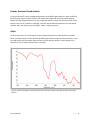
1
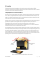
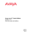
Installation and User Guide
IntegratIRTM Mid-IR Integrating Sphere
The information in this publication is provided for reference only. All
information contained in this publication is believed to be correct and
complete. PIKE Technologies, Inc. shall not be liable for errors contained herein
nor for incidental or consequential damages in connection with the furnishing,
performance, or use of this material. All product specifications, as well as the
information contained in this publication, are subject to change without notice.
This publication may contain or reference information and products protected
by copyrights or patents and does not convey any license under the patent
rights of PIKE Technologies, Inc. nor the rights of others. PIKE Technologies, Inc.
does not assume any liability arising out of any infringements of patents or
other rights of third parties.
This document contains confidential or proprietary information of PIKE
Technologies, Inc. Neither this document nor the information herein is to be
reproduced, distributed, used or disclosed, either in whole or in part, except as
specifically authorized by PIKE Technologies, Inc.
PIKE Technologies, Inc. makes no warranty of any kind with regard to this
material including, but not limited to, the implied warranties of merchantability
and fitness for a particular purpose.
Copyright 1991-2012 by PIKE Technologies, Inc., Madison, WI 53719. Printed in
the United States of America. All world rights reserved. No part of this
publication may be stored in a retrieval system, transmitted, or reproduced in
any way, including but not limited to, photocopy, photograph, magnetic or
other record, without the prior written permission of PIKE Technologies, Inc.
Address Comments to:
PIKE Technologies, Inc.
6125 Cottonwood Drive
Madison, WI 53719
Phone
Fax
E-mail
Web Site
Jan. 1, 2012
(608) 274-2721
(608) 274-0103
[email protected]
www.piketech.com
Contents
Introduction
1
Unpacking Your Accessory
2
Packing List
Installation
2
3
MCT Liquid Nitrogen Filling and Stabilization
Spectrometer Settings
3
4
Adjustment
Performance Verification
IR Sampling
4
4
5
Sample/Reference Selection Mirror
5
Transmission Sampling
6
Typical Spectra
6
Single Beam Spectrum
6
Powder, Paste and Liquid Analysis
7
Solids
7
Precautions
Replacement Parts and Options
8
8
APPENDIX
8
Introduction
IntegratIR™ Mid-Infrared Integrating Sphere series is an in-compartment sampling accessory for
measuring the diffuse reflection and diffuse transmission measurements of a wide variety of solid
materials. The IntegratIR™ module features a 3" high reflectivity gold-coated integrating sphere and a
high-speed, low-noise liquid nitrogen cooled Mercury-Cadmium-Telluride (MCT) detector or room
temperature DTGS detector with transfer optics and interface electronics. The detector connects to the
external detector port of the spectrometer.
The IntegratIR can also be used to measure diffusely transmitting samples. On the illumination port side
of the device there is a standard 2”x3” slide position mount, which allows thin samples such as polymer
films or other thin sheets of materials to be brought into the infrared beam. The integrating sphere,
positioned very close to the partially transmitting, partially scattering sample, collects all infrared light
emerging from the sample.
Two different spheres are available, an upward sample positioning 12° IntegratIR and downward sample
positioning 12° IntegratIR. The 12° integrating spheres include a specular exclusion port. The downward
sample positioning sphere is ideal for liquids, powders, and solids with dimensions less than 50 mm
width x 15 mm height. The upward sphere is suited for larger solids. An anti-reflective coated ZnSe
window for the upward sample positioning is available for powder samples. This manual covers the
downward sample positioning sphere only.
Detector Temperature
Indicators (MCT version only)
Specular
Exclusion Port
Detector Dewar
(MCT version only)
Purge Connectors
Sample Lift Lever
Sample/Reference
Position Lever
Sample Slot
Transmission Slider
Figure 1. Components of the Downward Sample Position MidIR IntegratIR Accessory
(shown equipped with an MCT detector; DTGS detectors do not require a Dewer )
PN 350-048000-00
P a g e |1
Unpacking Your Accessory
In order for you to quickly verify receipt of your accessory, we have included a packing list. Please
inspect the package carefully.
Packing List
IntegratIR User Manual
Downward IntegratIR Accessory
(shown with an MCT detector)
PN 350-048000
PN 048-11XX
Quantity 1
Quantity 1
Quantity 1
Spatula, brush, and spoon
Liquid Nitrogen Funnel
(for MCT version only)
Purge Kit
Quantity 1 each
Quantity 1
Quantity 1
Diffuse Gold Reference
Sample Cup
Sample Slide
PN 048-3001
PN 048-2020
Quantity 1
Quantity 1
Quantity 1
PN 350-048000-00
Detector Cable
P a g e |2
Installation
Before installation, make sure the spectrometer is working in the mid-infrared region without the
IntegratIR. Please consult the manufacturer of the FT-IR spectrometer for proper operation. This may
involve replacing the beam splitter and source to optimize for the 4000 to 500 cm-1 wavelength region of
the IntegratIR. It is advisable to perform an alignment of the interferometer before inserting the
IntegratIR into the sample compartment. Each IntegratIR unit is custom manufactured to interface with
a specific model FTIR Spectrometer. Operation with a different model may require a factory conversion
to be done by PIKE Technologies. Place the accessory in the sample compartment of the spectrometer.
The pin mounting of the accessory plate assures the alignment of the accessory relative to the beam
coming from the spectrometer. Connect the detector cable to the spectrometer while the spectrometer
powder is off.
CAUTION: Make sure power to the spectrometer bench is off before connecting the detector
cable.
For ThermoFisher instruments use the cable attached to the 15 pin D connector in the sample
compartment of the spectrometer. Select the appropriate source, optical path and detector. Please
consult the software manual provided by the spectrometer manufacturer concerning how to perform
the detector and source selection.
To connect the IntegratIR, please turn off the spectrometer. After the accessory detector cable is
connected to the instrument and the accessory, power up the instrument.
The accessory can be directly purged by connecting the purge tube kit to the purge connector located
on the purge collar and the accessory base (Figure 1).
MCT Liquid Nitrogen Filling and Stabilization (MCT Detector Configuration Only)
Fill the MCT detector with liquid nitrogen using the funnel included with the accessory.
WARNING: Wear safety goggles and protective clothing when handling liquid nitrogen. Exposure to
liquid nitrogen will cause severe skin or eye injury.
Pour a small amount of liquid nitrogen into the funnel and wait for it to drain into the Dewar of the
detector. Add additional small amounts of liquid nitrogen until the detector is filled. Allow the detector
to stabilize for about 10 minutes and then top it off with a final amount of liquid nitrogen to completely
fill the liquid nitrogen Dewar. A lit green LED light indicates the Dewar contains liquid nitrogen and is
beginning the detector cooling process or is sufficiently cooled. It is not an indication that the accessory
is necessarily ready for use. Be sure to wait a 10 minute equilibrium time after the Dewar has been
completely filled. Observing a stable interferogram is another indication that the accessory is ready for
measurements. An insufficiently cooled detector will produce a low and unsteady signal. The yellow LED
PN 350-048000-00
P a g e |3
light indicates the accessory is not ready for use. If the yellow LED is illuminated during use check that
the detector Dewar is filled with liquid nitrogen.
Spectrometer Settings
Set the collection parameters as follows
Wavelength Range: 5000 to detector cut off (650 cm-1 for midband MCT, 500 cm-1 for wideband
MCT, and 400 cm-1 for the DTGS detector)
Velocity: Select appropriate for MCT or DTGS detector for your FTIR spectrometer
Aperture: Appropriate J-stop
Resolution: 4 or 8 cm-1
Scan Time: 30-60 s
Due to different beam sizes of the various FTIR instruments the J-stop should be set a small enough
beam setting as not to overfill the sampling port or the specular exclusion port. This generally coincides
with an aperture setting appropriate for 4 cm-1 resolution. To check for the appropriate aperture setting,
place a 100% specular sample such as a mirror in the sample chamber and raise the specular sample to
the sphere using the sample lift lever. Monitor the energy while reducing the aperture. Choose the
largest aperture that coincides with the minimum energy. Typical residual energy with the specular
exclusion cap removed when measuring a 100% specular sample is 3.5% transmission.
Adjustment
The accessory has been aligned and tested to ensure that it performs to specifications and no additional
alignment is necessary.
Performance Verification
With the accessory installed, detector properly cooled for the MCT detector configuration and the
appropriate aperture set, insert the diffuse gold reference onto the sample slide and insert into the
sample chamber. Move the reference into the sample position by rotating the sample lift lever clockwise
to raise the sample to the sphere. Move the flipper mirror lever clockwise to position the mirror toward
the sample. Using a 1 minute data collect time, collect a background followed immediately by a sample
spectrum. The peak to peak noise between 2200 – 2000 cm-1 should be less than 0.3 %T for the
midband MCT detector, 1%T for the wideband MCT detector, and 3% for the DTGS detector. Typical
100% spectrum is shown in Figure 2.
PN 350-048000-00
P a g e |4
Figure 2. Example spectrum of 100% line for IntegratIR equipped with MCT (wideband)
Figure 3. Example spectrum of 100% line for IntegratIR equipped with DTGS (wideband)
PN 350-048000-00
P a g e |5
IR Sampling
The downward sample positioning sphere may be used to measure total hemispherical diffuse
reflectance, reflectance due to the diffuse component by collecting a sample spectrum with the specular
exclusion port cap removed, and diffuse transmission.
Sample/Reference Selection Mirror
The lever on the front right hand side of the sphere is used to change the position of the internal flipper
mirror. When in the right-hand position the flipper mirror directs the beam toward the sample at a 12o
angle; this is called the sample position. When in the left-hand position the beam is directed to the side
of the sphere; this is referred to as the reference position.
The flipper mirror can be left in the sample position and the background can be measured first using the
gold reference supplied with the IntegratIR. After the background is collected, the reference is
substituted with your sample and you may collect the sample spectrum. In this mode the
Sample/Reference flipper mirror lever should remain in sample position. This is called the substitution
method, because the reference is substituted with the sample.
The IntegratIR has another measurement mode, called the Taylor method. To conduct sample collection
via the Taylor method, load the sample into the sample chamber. Use the sample positioning lever to lift
the sample to the sphere sample port. Position the flipper mirror lever to the reference position, and
collect a background. To collect the sample spectrum, move the flipper mirror positioning lever to the
sample position to direct the beam to the sample and collect the spectrum. Figure 4 illustrates the lever
positioning for the sample lift and the sample/reference lever (flipper mirror).
Up
Down
Sample
Lift Lever
Reference
Sample
Sample/Reference
Lever
Figure 4. Sample lift lever and sample/reference lever positions
PN 350-048000-00
P a g e |6
Transmission Sampling
For diffuse transmission, insert the diffuse gold reference into the sample chamber and raise
the reference to the sphere by using the sample lift lever. Remove the transmission slide from
the beam entrance port, which will provide access to the built-in slide mount. Collect a
background spectrum. Place the transmission sample at the beam entrance port and collect the
sample spectrum.
Typical Spectra
Single Beam Spectrum
The spectral results using the IntegratIR depend to some degree on the spectrometer it is used with.
Source intensities, shape of the infrared beam, the beam splitter characteristics vary from bench to
bench, thus the single beam spectra could be slightly different. Using the diffuse gold reference or other
well characterized highly reflective standard and ratioing against this background corrects for the
individual throughput characteristics of the spectrometers.
Figure 5 shows a spectrum recorded at 4 cm-1 resolution showing ambient water vapor and CO2. Purging
the sample compartment will also reduce this effect for increased spectral reproducibility in the water
vapor and CO2 regions.
Figure 5. Single beam energy of the IntegratIR equipped with an MCT detector. The long wavelength cut off and
spectral noise is dependent on detector type and instrument configuration.
PN 350-048000-00
P a g e |7
Powder, Paste and Liquid Analysis
To obtain a spectrum, collect a background spectrum of the diffuse gold reference. Lower the diffuse
gold reference using the sample lift lever and remove the sample slide from the sample chamber.
Replace the diffuse gold reference from the sample slide with the sample cup. Be sure to level off the
sample in the case of a powder or paste/gel. Insert the sample slide and sample cup into the sample
chamber. Raise the sample cup to the sphere. Collect a sample spectrum.
Solids
To obtain a spectrum of a solid sample, collect a background spectrum as described in the powder,
paste, and liquid analysis section. Remove the diffuse gold reference from the sample chamber. Insert
the solid sample onto the sample slide or directly into the sample chamber. Lift the sample to the
sphere by move the sample position lever to the right.
Figure 6. Spectrum of diffusely scattering solid material collected using the IntegratIR equipped with an MCT
detector
PN 350-048000-00
P a g e |8
Precautions
In order to provide the maximum signal in the infrared, with the minimum spectral interference, the
mirrors used in this device are gold coated. Since the coatings are soft, care must be taken to avoid
damage. Normally, these mirrors will not need cleaning, since they are contained within the housing of
the accessory. If they do need cleaning, they may be gently wiped with a lint-free, abrasive-free cloth,
such as lens tissue, or with a camel hair brush. Under no circumstances must the mirrors be rubbed with
paper products such as “Kleenex” since this may produce scratching of the mirror coating.
Replacement Parts and Options
Part Number
Description
048-2020
048-3001
Sample Cup
Diffuse Gold Reference for Downward Sample Positioning Sphere
APPENDIX A
Recommended Measurement Parameters Range for FT-IR Spectrometers
Wavelength Range: 5000 to detector cut off (650 cm-1 for midband MCT, 500 cm-1 for wideband MCT,
and 400 cm-1 for the DTGS detector)
Velocity: select appropriate for MCT or DTGS detector for your FTIR spectrometer
Aperture: appropriate J-stop
Resolution: 4 or 8 cm-1
Scan time: 30 – 60 s
NOTE: Before installation, please turn the FTIR Bench off. In order to install the IntegratIR, the detector
cable has to be connected to the FTIR spectrometer electronics.
PN 350-048000-00
P a g e |9
6125 Cottonwood Drive · Madison, WI 53719-5120 · (608) 274-2721 (TEL) · (608) 274-0103 (FAX)
[email protected] · www.piketech.com