1
Getting Started for I-7000 Series Modules
Getting Started
For I-7000 Series Modules
Warranty
All products manufactured by ICP DAS are warranted against defective materials
for a period of one year from the date of delivery to the original purchaser.
Warning
ICP DAS assumes no liability for damage consequent to the use of this product. ICP
DAS reserves the right to change this manual at any time without notice. The information
furnished by ICP DAS is believed to be accurate and reliable. However, ICP DAS assumes
no responsibility for its use, or for any infringements of patents or other rights of third
parties resulting from its use.
Copyright
Copyright 1999 by ICP DAS. All rights are reserved.
Trademark
The names used for identification only may be registered trademarks of their
respective companies.
License
The user may not reproduce, transfer or distribute this manual, or any copy, in
whole or in part.
Date: Jan-08, 2002
Version 1.02
page: 1
Getting Started for I-7000 Series Modules
Table of Contents
1
Connecting Modules ......................................................................................................3
1.1 Connecting the first module .....................................................................................3
1.2 Connecting the second module................................................................................6
2 7000 Utility User’s Manual ...........................................................................................10
2.1 Introduction to the 7000 Utility................................................................................10
2.2 Installing the 7000 Utility ........................................................................................11
2.3 Uninstalling the 7000 Utility....................................................................................12
2.4 Starting the 7000 Utility ..........................................................................................14
2.5 Operating the 7000 Utility.......................................................................................16
2.5.1 Main Window of the 7000 Utility ............................................................
16
2.5.2 Stopping Search....................................................................................
16
2.5.3 Assigning COM Port, baud rate and checksum setting for Searching...
17
2.5.4 Invoking the Module Configuration Settings..........................................
18
2.5.5 Testing for all found modules ................................................................
20
2.5.6 Command Testing for a Module ............................................................
21
2.5.7 .MAP File Operation..............................................................................
23
2.6 Changing Baud Rate and Checksum .....................................................................24
2.7 Exiting the 7000 Utility............................................................................................25
3 NAP7000P ...................................................................................................................26
3.1 Writing your first NAP7000P program ....................................................................27
4 NAP7000X ...................................................................................................................33
4.1 Writing your first NAP7000X program ....................................................................34
5 Dual Watchdog ............................................................................................................37
5.1 Operating Principle ................................................................................................37
5.2 Host Watchdog ......................................................................................................38
5.3 Module Watchdog ..................................................................................................41
5.3.1 Does the module reset very frequently?................................................
43
5.4 Comparison of Host Watchdog and Module Watchdog..........................................44
5.5 Functions and Demo Programs .............................................................................45
5.5.1 Descriptions of Watchdog Demo...........................................................
46
6 FAQ .............................................................................................................................52
6.1 7000 FAQ...............................................................................................................52
6.2 MISC FAQ..............................................................................................................54
7 Reporting Problems .....................................................................................................56
Date: Jan-08, 2002
Version 1.02
page: 2
Getting Started for I-7000 Series Modules
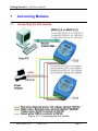
1
Connecting Modules
1.1
Connecting the first module
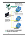
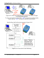
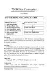
Figure 1-1-1. Connecting the first module
Date: Jan-08, 2002
Version 1.02
page: 3
Getting Started for I-7000 Series Modules
Connect the first module as in Figure 1-1-1. (If needed, replace the I-7012
module with your own and follow the diagram.) Please do not connect more
than one module at a time.
Install the 7000 Utility software from the included CD. Please refer to
chapter 2 of “The 7000 Utility User’s Manual”.
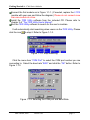
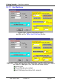
Run the 7000 Utility software to search for the user’s modules.
It will automatically start searching when users run the 7000 Utility. Please
click the icon
to stop it. Refer to Figure 1-1-2.
Figure 1-1-2. Stop searching.
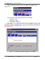
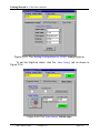
Click the menu item “COM Port” to select the COM port number you are
connecting to. Select the baud rate “9600” and click the “OK” button. Refer to
Figure 1-1-3.
Figure 1-1-3. Selecting the COM port and Baud Rate.
Date: Jan-08, 2002
Version 1.02
page: 4
Getting Started for I-7000 Series Modules
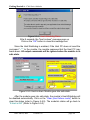
After reconfiguring, please click the icon
Figure 1-1-4.
to search again. See
Figure 1-1-4. Search the modules.
Every module has the following default factory settings:
• Address = 0x01
• Baud rate = 9600
• Checksum = disabled
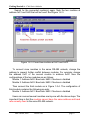
See Figure 1-1-5. If the 7000 Utility lists the module-ID “xxxx” in the
information window, congratulations! You have successfully connected the
first module and communicated with it. (Please do not connect more than one
module at a time.)
Figure 1-1-5. Showing the default settings of the module.
Date: Jan-08, 2002
Version 1.02
page: 5
Getting Started for I-7000 Series Modules
1.2
Connecting the second module
If you have two modules in the same RS-485 network and each module
has the same address and baud rate; they will conflict with each other.
Due to the factory settings, each module has the same address and
baud rate (address=0x01, baud rate=9600). Thus, users have to change the
configuration settings for each module to prevent further conflict. To change
the configuration on a specified module, double click on the module-ID that is
listed in the information window of the 7000 Utility. Refer to figure 1-1-5 and
2-6-4. To add a second module, change the address of the first module to
0x02 and then click on the “Setting” button. Refer to figure 1-2-1.
Figure 1-2-1. Changing the configuration settings.
The configuration settings of the first module:
Address: 0x02
Baud rate: 9600
Checksum: disabled
The configuration settings of the second module: (default factory settings)
Address: 0x01
Baud rate: 9600
Checksum: disabled
Now, users can connect the second module. See Figure 1-2-2.
Date: Jan-08, 2002
Version 1.02
page: 6
Getting Started for I-7000 Series Modules
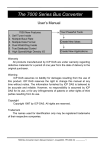
Figure 1-2-2. Connecting a second module
Date: Jan-08, 2002
Version 1.02
page: 7
Getting Started for I-7000 Series Modules
Search for the connected module(s) again. Note the two modules at
address 0x01 and 0x02 that will be found. See Figure 1-2-3.
Figure 1-2-3. Found two modules at 0x01 and 0x02.
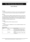
To connect more modules in the same RS-485 network, change the
address to prevent further conflict between modules. For example: change
the address 0x01 of the second module to address 0x03. Now the
configurations of the two modules are as follows:
Module 1: Address:0x02 Baud rate: 9600 Checksum: disabled
Module 2: Address:0x03 Baud rate: 9600 Checksum: disabled
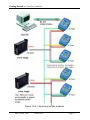
Then connect the third module as in Figure 1-2-4. The configuration of
third module contains the following pre-sets:
Module 3: Address:0x01 Baud rate: 9600 Checksum: disabled
Users can connect several modules one-by-one with the above steps. The
important thing is that the modules cannot have the same address and baud
rate currently used in the same RS-485 network.
Date: Jan-08, 2002
Version 1.02
page: 8
Getting Started for I-7000 Series Modules
Figure 1-2-4. Connecting multiple modules.
Date: Jan-08, 2002
Version 1.02
page: 9
Getting Started for I-7000 Series Modules
2
7000 Utility User’s Manual
1.Introduction to the 7000 Utility
2.Installating the 7000 Utility
3.Uninstalling the 7000 Utility
4.Starting the 7000 Utility
5.Operating the 7000 Utility
6.Changing baud rate and checksum
7.Exiting the 7000 Utility
2.1
Introduction to the 7000 Utility
The 7000 Utility is a software utility for the I-7000 series modules. It
works in multiple baud rate environments to meet the specifications of the
“Self-Tuner” in our I-7000 series modules. The 7000 Utility provides all of the
following functions:
Detects all I-7000 series modules connected to the Host PC.
Sets the configuration of the I-7000 series modules.
Executes data input and/or output for every connected I-7000 series
module.
Saves all information for each detected I-7000 series module into a
file (with .map extension file name).
Before using the 7000 Utility, please install it first. Please refer to the
following contents to complete the installation procedures.
Date: Jan-08, 2002
Version 1.02
page: 10
Getting Started for I-7000 Series Modules
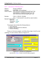
2.2
Installing the 7000 Utility
Before installing, please note and confirm the following requirements:
Microsoft Windows 95/98/ME/NT4.0/2000/XP Operating System.
32 MB RAM Memory.
20 MB hard disk available space.
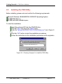
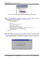
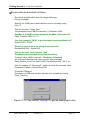
To start the Installation:
Insert the enclosed CD into the CD-ROM drive.
Click the “Run” item from the "Start" menu.
Enter the "[drive]:\NAPDOS\7000\7000Util\Setup.exe" as in Figure 22-1.
Click the “OK” button to start the installation procedures.
Follow the instructions in the installation procedures until completion.
D:\Napdos\7000\7000tuil\Setup.exe
Figure 2-2-1. Running "setup.exe" to install the 7000 Utility.
Date: Jan-08, 2002
Version 1.02
page: 11
Getting Started for I-7000 Series Modules
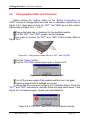
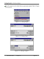
2.3
Uninstalling the 7000 Utility
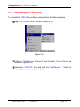
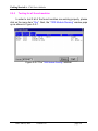
To uninstall the 7000 Utility software, please follow the following steps:
Open the “Control Panel” shown in Figure 2-3-1.
Figure 2-3-1
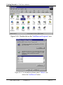
Click the “Add/Remove Programs” icon from the “Control Panel”, as
shown in Figure 2-3-2.
Select the “7000UTIL” item and click the “Add/Remove…” button to
uninstall it, as shown in Figure 2-3-3.
Date: Jan-08, 2002
Version 1.02
page: 12
Getting Started for I-7000 Series Modules
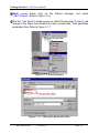
Figure 2-3-2. Double click on the “Add/Remove Programs” icon.
Figure 2-3-3. To uninstall the software, select “7000Util” and
click on the “Add/Remove” button.
Date: Jan-08, 2002
Version 1.02
page: 13
Getting Started for I-7000 Series Modules
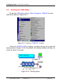
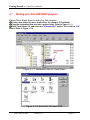
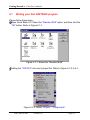
2.4
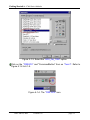
Starting the 7000 Utility
To start the 7000 Utility, click on “Start / Programs / 7000Util” from the
task bar as shown in Figure 2-4-1.
Figure 2-4-1. Click on “7000UTIL” to start.
When the 7000UTIL.EXE is loading, a window will pop up to show the
startup picture (Figure 2-4-2). By default, the startup window will stay onscreen for about 3 seconds.
Figure 2-4-2. Startup picture.
Date: Jan-08, 2002
Version 1.02
page: 14
Getting Started for I-7000 Series Modules
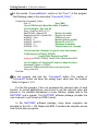
During startup, the 7000 Utility reads the “ICPCON.CFG” file to get the
COM port, baud rate and checksum information. After startup, the main
window of the 7000 Utility comes on and uses this information to
automatically start the searching process.
The 7000 Utility tests for a range of COM ports and baud rates in order
to search for the connected I-7000 series modules. If it fails to read the
“ICPCON.CFG“ file (for example, if it does not exist), the default setting for
the COM port is 2, the baud rate is 9600 and checksum is enabled. This
means that the search process would be limited to COM2 and the baud rate
speed would be 9600.
When quitting the 7000UTIL.EXE, the selected COM port numbers,
baud rates and checksum settings are stored into the “ICPCON.CFG” file.
Date: Jan-08, 2002
Version 1.02
page: 15
Getting Started for I-7000 Series Modules
2.5
2.5.1
Operating the 7000 Utility
Main Window of the 7000 Utility
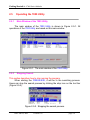
The main window of the 7000 Utility is shown in Figure 2-5-1. All
operations of the 7000 Utility are based on this main window.
Figure 2-5-1. The main window of the 7000 Utility
2.5.2
Stopping Search
This section describes how to stop running the program.
When starting the 7000Util.EXE, it will be in the searching process.
Users can stop the search process by clicking the stop icon on the tool bar
(Figure 2-5-2).
Figure 2-5-2. Stopping the search process.
Date: Jan-08, 2002
Version 1.02
page: 16
Getting Started for I-7000 Series Modules
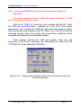
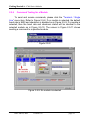
2.5.3
Assigning COM Port, baud rate and checksum setting for
Searching
This section describes how to change the search conditions for COM
port, baud rate and checksum status.
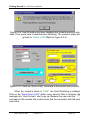
Click on the “COM Port” menu item, and a window with the title “Select
the COM port and Baud Rate…” appears as in Fig 2-5-3. This window
prompts the user to assign the COM port, baud rate and checksum status.
After configuration and clicking on the “OK“ button, the 7000 Utility starts the
searching process again. Any module that meets these conditions will be
recognized and shown in the information window.
These settings (include the COM port number, baud rate and
checksum) of the search conditions will automatically be stored into the
“ICPCON.CFG” when exiting the 7000 Utility.
Figure 2-5-3. Assigning the COM port, baud rate and checksum status for
the search process.
Date: Jan-08, 2002
Version 1.02
page: 17
Getting Started for I-7000 Series Modules
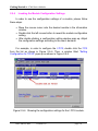
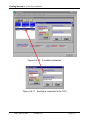
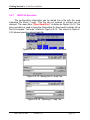
2.5.4
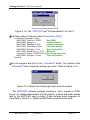
Invoking the Module Configuration Settings
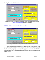
In order to see the configuration settings of a module, please follow
these steps:
• Move the mouse cursor onto the desired module in the information
window.
• Double click the left mouse button to reveal the module configuration
setting.
• After double clicking, a configuration setting window pops up. Adjust
the configuration settings according to the user’s demand.
For example, in order to configure the I-7012; double click the 7012
from the list as shown in Figure 2-5-4. Then, a window titled “Setting
Configuration for 7012D” pops up as shown in Figure 2-5-5.
Figure 2-5-4. Showing the configuration settings for the I-7012 module.
Date: Jan-08, 2002
Version 1.02
page: 18
Getting Started for I-7000 Series Modules
Figure 2-5-5. The “Setting Configuration for 7012D” window pops up.
To set the High/Low alarm, click the “Alarm Setting” tab as shown in
Figure 2-5-6.
Figure 2-5-6 The “Alarm Setting” tabbed page.
Date: Jan-08, 2002
Version 1.02
page: 19
Getting Started for I-7000 Series Modules
2.5.5
Testing for all found modules
In order to test if all of the found modules are working properly, please
click on the menu item “Run”. Next, the “7000 Module Running” window pops
up as shown in Figure 2-5-7.
Figure 2-5-7 The “7000 Module Running” window.
Date: Jan-08, 2002
Version 1.02
page: 20
Getting Started for I-7000 Series Modules
2.5.6
Command Testing for a Module
To send and receive commands, please click the “Terminal / Single
Line” menu item. Refer to Figure 2-5-8. If no module is selected, the default
baud rate is 9600 and checksum is disabled as in Figure 2-5-9. If a module is
selected, then the baud rate and checksum status will be identical to the
selected module as in Figure 2-5-10. The screen in Figure 2-5-11 shows
sending a command to a specified module.
Figure 2-5-8
Figure 2-5-9. No module is selected
Date: Jan-08, 2002
Version 1.02
page: 21
Getting Started for I-7000 Series Modules
Figure 2-5-10. A module is selected.
Figure 2-5-11. Sending a command to the 7012
Date: Jan-08, 2002
Version 1.02
page: 22
Getting Started for I-7000 Series Modules
2.5.7
.MAP File Operation
The configuration information can be stored into a file with the .map
extension file name (*.map). This file can be opened or printed out on
demand. The menu item “Open/Save/Print” is shown as Figure 2-5-12. The
save operation is used to save the information for discovered modules into a
file (for example: “test.map”). Refer to Figure 2-5-13. The screen in Figure 25-14 shows opening a stored map file.
Figure 2-5-12. The “Open/Save/Print” menu item.
Figure 2-5-13. Saving into a “.map” file.
Figure 2-5-14. Opening a “.map” file.
Date: Jan-08, 2002
Version 1.02
page: 23
Getting Started for I-7000 Series Modules
2.6
Changing Baud Rate and Checksum
Before clicking the “Setting” button on the “Setting Configuration for
XXXX” window to change either the baud rate or checksum, please refer to
Figure 2-5-5. Users have to short the “INIT*” and “GND” pins of this module.
Please refer to Figure 2-6-1 ~ 2-6-3.
Change the baud rate or checksum for the specified module.
Turn the "INIT*" and "GND" screws counter-clockwise.
Use a wire to connect the “INIT*” and “GND” of this module. Refer to
Figure 2-6-1.
Figure 2-6-1. Using a wire to short the pin of “INIT*” and “(B) GND”.
Click the “Setting” button.
Then the 7000 Utility window pops up as in Figure 2-6-2.
Setting Configuration OK !!
Please Turn off the pow er of 7000 m odule,
then Turn On again to take effect the setting!!!
Figure 2-6-2. Setting Configuration OK!!
Turn off the power supply of this module and then turn it on again.
Search to ensure that the settings are correct.
A window like the one shown in Figure 2-6-3 indicates failure. Check the
"INIT*" and "GND" connections, and then follow the steps listed above. If the
Figure 2-6-3 is received again, consult your local distributor.
Figure 2-6-3. The “INIT*” and “GND” do not connect correctly.
Date: Jan-08, 2002
Version 1.02
page: 24
Getting Started for I-7000 Series Modules
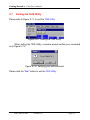
2.7
Exiting the 7000 Utility
Please refer to Figure 2-7-1 to quit the 7000 Utility.
Figure 2-8-1. Exiting the 7000 Utility.
When exiting the 7000 Utility, a window prompt verifies your command
as in Figure 2-7-2.
Figure 2-7-2. Verifying your exit command.
Please click the “Yes” button to exit the 7000 Utility.
Date: Jan-08, 2002
Version 1.02
page: 25
Getting Started for I-7000 Series Modules
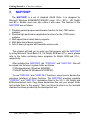
3
NAP7000P
The NAP7000P is a set of standard Win32 DLLs. It is designed for
Microsoft Windows 95/98/ME/NT/2000/XP users. VC++, BC++, VB, Delphi
and BC++ Builder users can also utilize it with ease. The features of the
NAP7000P are as follows:
1. Provides general-purpose send/receive function for the I-7000 series
modules.
2. Provides high performance application functions for the I-7000 series
modules.
3. Multi-speed (baud rates) demo programs.
4. Multi-data-format demo programs.
5. Lots of demo programs with complete source code.
This chapter will lead you to write your first program with the NAP7000P
by using Microsoft Visual Basic 5.0. For Delphi, BCB and VC++ users, please
refer to the folder containing demo programs for Delphi, BCB and VC++,
respectively.
After installing the NAP7000P, the “I7000.DLL” and “UART.DLL” files will
be copied into the user’s system folder as follows :
C:\Windows\system (Windows 95/98/ME)
C:\WinNT\System32 (Windows NT/2000/XP)
To use "I7000.DLL" and "UART.DLL" functions, users have to declare the
prototype (interface) of these functions. The NAP7000P provides complete
"I7000.DLL" and "UART.DLL" declaration files for the VC++, VB, Delphi and
BCB development tools. Copy these declaration files into your project folder
and include them in this project. Then use these functions as the included
standard functions provided by the development tool.
Date: Jan-08, 2002
Version 1.02
page: 26
Getting Started for I-7000 Series Modules
3.1
Writing your first NAP7000P program
Please follow these steps to write your first program :
Create a new folder for user’s project files, for example: E:\Test\Start1
Copy the declaration files into user’s project folder. Refer to Figure 3-1-1.
Open Visual Basic 5.0, and select the “Standard EXE” option. Then click the “OK”
button. Refer to Figure 3-1-2.
Figure 3-1-1. Declaration files for Visual Basic.
Figure 3-1-2. Select the “Standard EXE"
Date: Jan-08, 2002
Version 1.02
page: 27
Getting Started for I-7000 Series Modules
Save the project into the folder that you previously created. Refer to Figure
3-1-3 to 3-1-5.
Figure 3-1-3. Saving Project
Figure 3-1-4. Saving "form1"
Figure 3-1-5. Saving "Project1".
Date: Jan-08, 2002
Version 1.02
page: 28
Getting Started for I-7000 Series Modules
Right mouse button click on the Project manager, and select
“Add”/”Module”. Refer to Figure 3-1-6.
After the “Add Module” window pops up, select the tab page “Existing” and
change to the folder that contains the user’s project files. Then add these
declaration files. Refer to Figure 3-1-7.
Figure 3-1-6. Adding Module
Figure 3-1-7. Adding the declaration files
Date: Jan-08, 2002
Version 1.02
page: 29
Getting Started for I-7000 Series Modules
Figure 3-1-8. Declaration files have been added into this project.
Put a “CommandButton” control on “Form1” of this program. Add the
following codes in the sub routine “Command1_Click() “ :
Private Sub Command1_Click()
Dim wt As Integer
Port = 2
Open_Com Port, 9600, 8, 0, 0
SendTo7000 = "$01M"
ReceiveFrom7000 = Space(100)
Send_Receive_Cmd Port, SendTo7000, ReceiveFrom7000, 100, 0, wt
Command1.Caption = ReceiveFrom7000
Close_Com Port
End Sub
Run the program and click on the “Command1” button. The caption of the
“Command1” button will be changed to “!01xxxx”. The “!” is “OK”. The “01”
means “address at 0x01”. The “xxxx” is the module-ID. Refer to Figure 3-19.
Figure 3-1-9. The module returns “!01xxxx”.
Date: Jan-08, 2002
Version 1.02
page: 30
Getting Started for I-7000 Series Modules
These codes are described as follows :
‘Declare a variable which has the Integer data type.
Dim wt As Integer
‘Specify the COM port number that the user is currently using
Port = 2
‘Call the function “Open_Com”
‘the parameters are COM Port number: 2, Baubrate: 9600,
‘DataBits: 8, ParityBit: 0(None parity bit), StopBits: 0(One stop bit)
Open_Com Port, 9600, 8, 0, 0
‘Use this command “$01M” to get the module name at address 0x01
SendTo7000 = "$01M"
‘Declare a space to store the string of returned value
ReceiveFrom7000 = Space(100)
‘Call the function “Send_Receive_Cmd”
‘Parameters are Command String, Returned String,
‘Timeout value: 100(0.1 second) , Checksum: 0(disabled)
‘wt: will report the time has been used for this command
Send_Receive_Cmd Port, SendTo7000, ReceiveFrom7000, 100, 0, wt
‘Use the caption of “Command1” button to show the returned value
Command1.Caption = ReceiveFrom7000
‘Close the COM port
‘Parameter is COM port number that the user opened previously.
Close_Com Port
Figure 3-1-10. Use function “AnalogIn” to get the analog input value
Date: Jan-08, 2002
Version 1.02
page: 31
Getting Started for I-7000 Series Modules
Put the second “CommandButton” control on the “Form1” of this program.
Add following codes in the subroutine “Command2_Click()” :
Private Sub Command2_Click()
'Use COM2
Port = 2
'Open COM Port with Baud Rate 9600, 8 DataBits,
‘None Paritybits , One stop bit
Open_Com Port, 9600, 8, 0, 0
'Declare the buffer
SendTo7000 = Space(100)
'Declare the buffer
ReceiveFrom7000 = Space(100)
'COM port in use
w7000(0) = Port
'Module Address at 0x01
w7000(1) = 1
'Module ID is 0x7013
w7000(2) = &H7013
'Checksum 0:disabled
w7000(3) = 0
'Timeout value is 0.1 second
w7000(4) = 100
'Call the function "AnalogIn" to get the value from module
'Parameters are w7000(0), f7000(0),
'
SendTo7000, ReceiveFrom7000
AnalogIn w7000(0), f7000(0), SendTo7000, ReceiveFrom7000
'Use the caption of "Command2" button to show the value
Command2.Caption = f7000(0)
'Close the COM port that the user open previously
Close_Com Port
End Sub
Run the program and click the “Command2” button. The caption of
“Command2” button will show the analog input value from the module.
Refer to Figure 3-1-10.
For the first program, it has not processed the returned value of each
function. In normal applications, users have to get the returned value and
process it. For detailed descriptions of every function, please refer to the
NAP7000P user’s manual. The NAP7000P software package provides the
user’s manual in .pdf format (or HTML format).
In the NAP7000P software package, many demo programs are
provided for the VC++, VB, Delphi and BCB. It contains the complete source
code for the demo programs.
Date: Jan-08, 2002
Version 1.02
page: 32
Getting Started for I-7000 Series Modules
4
NAP7000X
The NAP7000X is an ActiveX Control (OCX) for the I-7000 series module.
It enables you to develop programs quickly and easily. Before using the
NAP7000X, users must install it. Please refer to the NAP7000X user’s
manual.
This chapter will teach you to write your first NAP7000X program by using
Microsoft Visual Basic 5.0.
After installation, the “I7000.DLL”, “UART.DLL”, “I7000.TLB”
and
“I7000.OCX” files will be copied into the user’s system folder as follows :
C:\Windows\system (Windows 95/98)
C:\WinNT\System32 (Windows NT/2000/XP)
Date: Jan-08, 2002
Version 1.02
page: 33
Getting Started for I-7000 Series Modules
4.1
Writing your first NAP7000X program
Please follow these steps :
Open Visual Basic 5.0. Select the “Standard EXE” option, and then click the
“OK” button. Refer to Figure 4-1-1.
Figure 4-1-1. Select the “Standard EXE"
Adding the “7000OCX” into user’s project file. Refer to Figure 4-1-2 to 4-13.
Figure 4-1-2. Select “Project” / “Components”.
Date: Jan-08, 2002
Version 1.02
page: 34
Getting Started for I-7000 Series Modules
Figure 4-1-3. Select the “OCX_For_7000” option.
Click on the “7000OCX“ and "CommandButton" from on “Form1”. Refer to
Figure 4-1-4 to 4-1-5.
Figure 4-1-4. The “7000 OCX” icon.
Date: Jan-08, 2002
Version 1.02
page: 35
Getting Started for I-7000 Series Modules
Figure 4-1-5. The “7000 OCX” and "CommandButton" on Form1.
Add these codes in the sub routine “Command1_Click()”
Private Sub Command1_Click()
'Use COM2
NAP7000X1.ComPort = COM2
'module address: 1
NAP7000X1.Address = 1
'setting the baudrate
NAP7000X1.BaudRate = 9600
'checksum disable
NAP7000X1.CheckSum = False
'Open the ComPort
NAP7000X1.PortOpen = True
NAP7000X1.ModuleType = I_7013 'Module ID
Command1.Caption = NAP7000X1.AI 'Get Analog input value
'Close the ComPort
NAP7000X1.PortOpen = False
End Sub
Run the program and click on the “Command1” button. The caption of the
“Command1” button shows the analog input value. Refer to Figure 4-1-6.
Figure 4-1-6. Shows the analog input value from the module.
The NAP7000X software package provides a user’s manual in HTML
format. For detailed descriptions of each property, method and event, please
refer to the NAP7000X user’s manual. It also contains demo programs for
Visual Basic, Visual C++, Delphi and BCB with complete source code.
Date: Jan-08, 2002
Version 1.02
page: 36
Getting Started for I-7000 Series Modules
5
Dual Watchdog
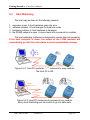
5.1
Operating Principle
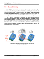
All I-7000 series modules equip both a hardware module watchdog and a
software host watchdog. The I-7000 series modules are specially designed
for industry applications, and can work under any conditions. Harsh
environments may contain excessive noise or energy transient. In this case,
the modules will be adversely affected. However, the built-in hardware
module watchdog resets the module if these forces affect the module
(see Figure 5-3-1) . Sometimes even the host-PC may be down for hardware
or software reasons. The software host watchdog monitors the status of
host-PC. If the host-PC goes down, all output of the I-7000 series modules
will go to predefined safe states for safety protection. Refer to Figure 5-2-1 to
5-2-3) .
If the RS-485 network is open, host commands can not be sent to remote
modules. This is very dangerous in real world applications. The I-7000
output-module (AO/DO) will force the output to go to the pre-defined safe
states for safety consideration if the host watchdog is actived. This dual
watchdog feature increases the reliability of the whole system.
Dual watchdog = module watchdog + host watchdog
Host watchdog: (software/firmware)
if the host is down !
all output goes to safe state (Safe value).
(refer to Figure 5-2-1 ~ 5-2-4).
Module watchdog: (hardware)
if the module is down !
reset this module and the module’s output reverts to PowerOn values.
(refer to Figure 5-3-1 ~ 5-3-2).
Date: Jan-08, 2002
Version 1.02
page: 37
Getting Started for I-7000 Series Modules
5.2
Host Watchdog
The host may be down for the following reasons:
1.
2.
3.
4.
excessive noise ! host hardware goes into error
software problem ! host changes to dead lock mode
hardware problem ! host hardware is damaged
the RS485 network is open ! cannot send out commands to modules
The host-watchdog (software) is designed to monitor the host computer.
If the host computer is down, the output of the I-7000 modules will
automatically go into their safe states to avoid unpredictable damage.
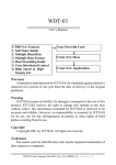
Figure 5-2-1. Host PC sends the “~**” command to every module.
The Host PC is OK.
Figure 5-2-2. Host PC cannot send command to any module.
Every Host-Watchdog sets its module to go into safe state.
Date: Jan-08, 2002
Version 1.02
page: 38
Getting Started for I-7000 Series Modules
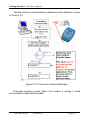
Figure 5-2-3. After Host-Watchdog sets module to safe state, all output
commands will be ignored.
To clear, the host PC must send the “~AA0” command to read the module
status, and the “~AA1” command to clear the module status.
Note the flow chart for the host computer in Figure 5-2-4.
Figure 5-2-4. Flow chart of Host-Watchdog.
Date: Jan-08, 2002
Version 1.02
page: 39
Getting Started for I-7000 Series Modules
Demo: The host-watchdog and safe values for the I-7060 module.
Please refer to hardware manual for more detailed information.
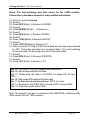
01. Power on and run test.exe
02. Press 2
03. Press $012 [Enter] ! Receive=!01400601
04. Press 2
05. Press #01000F [Enter] ! Receive =>
06. Press 2
07. Press $016 [Enter] ! Receive=!0F0F00
08. Press 2
09. Press ~014S [Enter]! Receive=!0F0F00
10. Press 2
11. Press ~01311E [Enter]! Receive=!01
12. Wait 3 seconds. The led of 7060 should flash and all relay outputs should
be OFF. This action simulates host computer failure. The host watchdog
is now activated. All relay outputs revert to their safe states.
13. Press 2
14. Press $016 [Enter] ! Receive=!01000F00
15. Press 2
16. Press ~011 [Enter] ! Receive = !01
Step 03: This is an I-7000 DIO module. Baud rate=9600.
Step 05: Sets all relay outputs to ON State.
Step 07: Reads back the state of all DI/DO: all relays ON, all input
HIGH
Step 09: Sets current D/O states as the safe-value
Step 11: Enables the host watchdog and timer, 1EH*0.1s = 3 sec.
Step 14: Reads back the DI/DO state: all relays OFF, all input HIGH.
Step 16: Clear the module status to 00
Note: The program “test.exe” is contained in the NAP7000S, a software utility
(DOS version) for all I-7000 modules.
Date: Jan-08, 2002
Version 1.02
page: 40
Getting Started for I-7000 Series Modules
5.3
Module Watchdog
The I-7000 series modules are designed for industry applications. They
can be used under any conditions. Sometimes industry environments will
contain excessive noise or energy transient. The module might be affected
if these noises are excessive. If the working environment is not noisy, the
well-designed firmware will enable the I-7000 modules to run for years.
The $AA5 command is designed to detect module-watchdog
failures. If the module is down, the module-watchdog (hardware circuit)
will reset this module. After reset, the output state of the module will revert
to pre-defined Power-On values. The Power-On values may be different from
the output-values previously used. Therefore, after the module-watchdog
resets, send the output command again to the module to restore the
previous Output State values.
Figure 5-3-1. Module-Watchdog will reset the module
when the module fails.
Date: Jan-08, 2002
Version 1.02
page: 41
Getting Started for I-7000 Series Modules
The flow chart for module-watchdog (hardware) failure detection is given
in Figure 5-3-2.
Figure 5-3-2. Flow chart of Module Watchdog.
Frequently checking module status if the module is working in harsh
environments is highly recommended.
Date: Jan-08, 2002
Version 1.02
page: 42
Getting Started for I-7000 Series Modules
5.3.1
Does the module reset very frequently?
If the module resets frequently, it may occur due to the following
reasons.
Excessive noise
The I-7000 series modules are designed for industry applications
and difficult environments. Often, these environments contain
excessive noise or energy transient which can disable your module.
Reducing your environment's excess noise level improves both
the stability and reliability of your application.
Module(hardware) is going to break down.
When a module cannot read data or produces bad output, it
may because the module is going to break down. The user should
replace this module ASAP.
It is important to check if your module has been reset, because the
module’s output will revert to Power-On values after the module has been
reset. The Power-On value may be not appropriate, or may be dangerous, for
your job. Resetting the module to your desired values ensures your module
will work correctly.
Date: Jan-08, 2002
Version 1.02
page: 43
Getting Started for I-7000 Series Modules
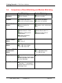
5.4
Comparison of Host Watchdog and Module Watchdog
Host Watchdog
Module Watchdog
Software or
Hardware
Software Watchdog
Built-in firmware
Hardware Watchdog
Circuits in module
Purpose
To monitor the Host PC
For use in all output modules
To monitor the Module
For use in all modules
When activation
occurs
Host is down
Communication line
is broken
What to do
Module goes to safe state
Module status S = 0x04
Module’s output goes to
safe values
All output commands
will be ignored.
CLEAR modulestatus
~AA1
S is set to 0
READ modulestatus
~AA0
S = 4 " Host is down
S = 0 " Host is OK
READ and RESET
module-reset –
status
Module fails
Excessive work environment
noise
Module resets
Module Reset status S = 1
Module’s output goes to
PowerOn values
$AA5
S = 1 " Module Reset
S = 0 " Not reset
Setup steps
Setup safe values
Setup the timer interval value
of Host Watchdog and enable
the Host Watchdog
Send “Host is OK”
~**
Send the "~**" command to
modules before timeout of Host
Watchdog’s timer.
Date: Jan-08, 2002
Version 1.02
Setup Power-On values
page: 44
Getting Started for I-7000 Series Modules
5.5
Functions and Demo Programs
There are several functions designed for the Watchdog. For detailed
information about these functions, please refer to the NAP7000P user’s
manual. These functions are listed as follows:
HostIsOK : Tells all modules "Host is OK" by sending the "~**" command.
ReadModuleResetStatus : Reads the module reset status.
ToSetupHostWatchdog : Sets up the module's Host Watchdog.
ToReadHostWatchdog :
Reads the module's Host Watchdog setup values.
ReadModuleHostWatchdogStatus :
Reads the module's Host Watchdog status.
ResetModuleHostWatchdogStatus :
Resets the module's Host Watchdog status.
SetSafeValueForDo : Sets up the safe values for DO modules.
SetPowerOnValueForDo : Sets up the power on values for DO modules.
SetSafeValueForAo : Sets up the safe values for AO modules.
SetPowerOnValueForAo : Sets up the power on values for AO modules.
SetPowerOnSafeValue :
Sets up the power on and safe values for modules.
There are some sample programs for the Watchdog. They are written
in VB, Delphi and BCB computer languages, and placed into their respective
demo folders. These demo programs are listed as follows:
SafeAI
: Host Watchdog and Safe value demo for analog input modules.
SafeAO
: Host Watchdog and Safe value demo for analog output modules.
SafeDO
: Host Watchdog and Safe value demo for digital output modules.
Watchdog : Host Watchdog and Module Watchdog demo.
Users can find these functions and demo programs in the NAP7000P
version 3.3.
Date: Jan-08, 2002
Version 1.02
page: 45
Getting Started for I-7000 Series Modules
5.5.1
Descriptions of Watchdog Demo
Platform
: Windows 95/98/NT
Software
: NAP7000P v3.30 (or above)
Demo Program : NAP7000P\Demo\Delphi\Watchdog\Project1.dpr
NAP7000P\Demo\BCB\Watchdog\Project1.bpr
NAP7000P\Demo\VB\Watchdog\Project1.vbp
Modules
: 7520 x 1 (RS-232 / RS-485)
70xx x 1 (recommend for use with an output module)
Module Configuration :
Baud rate : 9600
Checksum : disable
Address : 0x01
This program demonstrates the following features:
1. Host Watchdog.
2. Broken communication line detection.
3. Module Watchdog.
Please run the demo program, and follow those steps to test the dual
watchdog. The main window is shown as Figure 5-5-1.
Figure 5-5-1. Choose your configuration
and click the “Active” button to start this demo program.
Date: Jan-08, 2002
Version 1.02
page: 46
Getting Started for I-7000 Series Modules
5.5.1.1
Host Watchdog
Figure 5-5-2. Type in time-interval value
and click on the “Setup Host Watchdog” button.
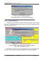
Figure 5-5-3. After setting up the Host-Watchdog, read the status and all preset values. In example 5-5-3, the user has these values:
0:Host is OK.
1:Host Watchdog is enabled.
Host Watchdog time interval is 5 seconds.
Date: Jan-08, 2002
Version 1.02
page: 47
Getting Started for I-7000 Series Modules
Figure 5-5-4. Host-Watchdog Demo.
After 5 seconds, the "host is down" message pops up.
Click on the “OK” button to close this message box.
Since the Host-Watchdog is enabled, if the Host PC does not send the
command “~**” to the module, the module supposes that the Host PC may
break down. All output commands will be ignored when the module is in
safe state.
Figure 5-5-5. Host is down. Module goes into safe state.
After the module goes into safe state, the module’s Host-Watchdog will
be disabled automatically. Click on the “Clear [Host failure mode]” button to
clear this status (refer to Figure 5-5-5). The module’s status will go back to
“0:Host is OK!” (Refer to Figure 5-5-3).
Date: Jan-08, 2002
Version 1.02
page: 48
Getting Started for I-7000 Series Modules
Figure 5-5-6. Host Watchdog has been disabled after module reverts to safe
state. Thus, users have to reset the Host Watchdog. The module’s status will
go back to “0:Host is OK!”(Refer to Figure 5-5-3).
Figure 5-5-7. Send the “[Host is OK]” command to the module every second.
When the module’s status is “0:OK”, the Host Watchdog is enabled.
Click on the “Send [Host is OK]” button every second. After 5 seconds, the
message box “Host is down” won’t pop up. Because the user sent the “~**“
command to this module, the module knew that the connection with the Host
was active.
Date: Jan-08, 2002
Version 1.02
page: 49
Getting Started for I-7000 Series Modules
Figure 5-5-8. Type 0 in the Host-Watchdog’s time interval edit box. Click the
“Setup Host Watchdog” button to disable it.
5.5.1.2
Broken communication line detection
Figure 5-5-9. Normally, the Module Reset Status is 0.
Now, please disconnect the RS-232 cable from the I-7520 module. This
is used to simulate a broken communication line. After x seconds (determined
by the sample program), a message box pops up to tell the user that the
communication line is broken between the computer and the module (refer to
Figure 5-5-10).
Date: Jan-08, 2002
Version 1.02
page: 50
Getting Started for I-7000 Series Modules
Figure 5-5-10. Communication line is broken.
Click on the “OK” button to close it.
(This feature doesn’t involve the Dual Watchdog.)
5.5.1.3
Module Watchdog
Please connect the RS-232 cable to the I-7520 module again. Unplug
the user’s I-70xx module, then plug it in again. The "Reset" message box will
pop up as in Figure 5-5-11.
Figure 5-5-11. Module-Watchdog Demo.
Module has been reset. Output goes to Power-On values.
Click on the “OK” button to close it.
The Power-On value may be not appropriate and may be dangerous for
your job. Thus, correct the output values again to fit your specifications.
Date: Jan-08, 2002
Version 1.02
page: 51
Getting Started for I-7000 Series Modules
6
FAQ
6.1
7000 FAQ
Q: How to compute the checksum?
A:
The steps to compute the checksum are given as follows:
Step 1: Checksum=0;
Step 2: Sums all "Command byte" with index conduct this loop:
Checksum = Checksum + Command byte [index]
Step 3: Checksum = Checksum & 0xff
Step 4: Convert Checksum to ASCII high byte and ASCII low byte
For example,
Command = $012[Enter]
Checksum = '$'+'0'+'1'+'2' = 0x24+0x30+0x31+0x32 = 0xB7
Checksum & 0xff = 0xB7
Checksum high byte = 'B'
Checksum low byte = '7'
Command with checksum = $012B7[Enter]
Q: When to use a repeater in the RS-485 network?
A:
Users should use a repeater if the network has more than 256 modules,
or if it is being sent farther than 1.2 km.
Date: Jan-08, 2002
Version 1.02
page: 52
Getting Started for I-7000 Series Modules
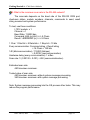
Q: What is the maximum scan-rate in the RS-485 network?
A:
The scan-rate depends on the baud rate of the RS-232 COM port,
checksum status, module numbers, channels, commands to send, result
string received and system performance.
To test, use those conditions:
I-7012 module: x 1
Channel: x 1
Baud Rate: 115200 bps
Command: #AA (cr)(null) ==> 5 Chars
Result: >SDDDDDD (cr) ==> 9 Chars
1 Char: 1 Start bit + 8 Data bits + 1 Stop bit = 10 bits
Every communication: Command string + Result string
= 14 Chars = 140 bits
140 (bits/communication) / 115200 (bits/sec)
= 0.00122 (sec/communication)
Hardware delay (every communication): 1 mSec
Scan rate: 1/ (0.00122 + 0.001) = 450 (communication/sec)
Estimated scan rate:
450 times/sec maximum.
Tested value of scan rate:
440 times/sec maximum without system message processing.
360 times/sec maximum with system message processing.
Note: System message processing lets the OS process other tasks. This may
reduce the program performance.
Date: Jan-08, 2002
Version 1.02
page: 53
Getting Started for I-7000 Series Modules
6.2
MISC FAQ
Q: Why doesn't the ComboBox's CHANGE event work with VB?
A:
In Delphi and Borland C++ Builder, the "CHANGE" event works
correctly when users choose the item from "ComboBox". But, Visual Basic,
this event only occurs when users code in the “CLICK” event to do the same
work. This “CLICK” event also works correctly in Delphi and Borland C++
Builder.
Q: How do you prevent TIMER events from reoccurring?
A:
If the “TIMER” object is used, please ensure the set Interval values of
the “TIMER” object are appropriate for your program, system and hardware.
Suppose the “TIMER” object triggers an event to do something, and
then re-triggers the event to do the same work before the prior job has ended.
This may cause two jobs run concurrently. Over time, this might crash the
user’s system. If many jobs are running at the same time; the system could
overload.
To prevent a system crash with the “TIMER” object, note the following
"TIMER" event situation. Please do not give the TIMER object simultaneous
jobs, per the example below.
bool bProcessing ; // declare a flag
void __fastcall TForm1::FormCreate(TObject *Sender)
{ bProcessing = false; }
void __fastcall TForm1::Timer1Timer(TObject *Sender)
{ if (bProcessing == true)
return ; // avoid reenter
else
Date: Jan-08, 2002
Version 1.02
page: 54
Getting Started for I-7000 Series Modules
bProcessing = true;
........................
........................
// if (something wrong ) {
//bProcessing = false; // enable next timer event to enter
//return;
//}
........................
........................
bProcessing = false; // enable next timer event to enter
}
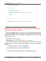
Q: What if I receive the "Unable to create process" error message with
Borland C++ Builder and Delphi?
A:
This error message could have occurred if a .DLL file could not be found in
your system. Please create a .exe file for this program and then run the
execution file. Different error messages may appear as follows; here are
explanations for each.
Error Title: Error Starting Program
Error Message: A required .DLL file, XXXX.DLL, was not found.
Note what .DLL files are missed. Copying the specific .DLL files into the
system folder of Windows will solve this problem. In general, the system
folder is:
C:\Windows\system (for Windows 95/98/ME)
Or C:\WinNT\System32 (for Windows NT/2000/XP)
If needed, check the Windows settings to find the system folder.
Date: Jan-08, 2002
Version 1.02
page: 55
Getting Started for I-7000 Series Modules
7
Reporting Problems
Technical support is available at no charge. The best way to report
problems is sending e-mail to
[email protected]
on the Internet.
When reporting problems, please include the following information:
1) Is the problem reproducible? If so, how?
2) What operation system is being used? For example, DOS, Windows 3.1, Windows
95/98/ME, Windows NT 4.0 and Windows 2000/XP, etc.
3) Which ICPDAS product are you using? Please see the product manual for the product
number. For example: I-7012, I-7017, I-7060, I-8410 and I-87056, etc.
4) If a dialog box with an error message was displayed, please include the full text of the
dialog box, including the text in the title bar.
5) If the problem involves other programs or hardware devices, what devices and/or
version of the other program are you using?
6) Other comments related to this problem or any suggestions will be welcomed.
After we have received your comments, our engineers will take about two
business days to test for your problem, and will reply on the results as soon
as possible. Please verify that you have received our comments… and please
keep in touch with us.
E-mail: [email protected]
Date: Jan-08, 2002
Version 1.02
page: 56