1
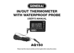
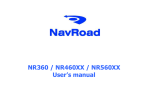
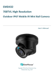
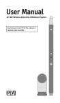
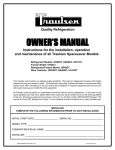
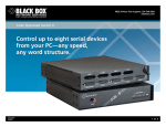
INSIDE-OUTSIDE
THERMOMETER
WITH MIN/MAX MEMORY
USER’S MANUAL
DTR900
Please read this manual carefully
and thoroughly before using this product.
TABLE OF CONTENTS
Introduction . . . . . . . . . . . . . . . . . . . . . . 3 – 4
Key Features . . . . . . . . . . . . . . . . . . . . . . . . 4
What’s In the Box . . . . . . . . . . . . . . . . . . . . . 5
Product Overview . . . . . . . . . . . . . . . . . 5 – 7
Setup Instructions . . . . . . . . . . . . . . . . 7 – 13
Activate the Unit . . . . . . . . . . . . . . . 7 – 8
Choose Your Temperature
Unit & Time and Date Format . . . . 9 – 10
Set the Time and Date . . . . . . . . 11 – 12
Extend and Secure the
External Sensor Cable . . . . . . . . . . . . 13
Operating Instructions . . . . . . . . . . . . 14 – 17
Specifications . . . . . . . . . . . . . . . . . . . . . . 17
Maintenance Tips . . . . . . . . . . . . . . . . . . . 18
Warranty Information . . . . . . . . . . . . 18 – 19
Return for Repair Policy . . . . . . . . . . 19 – 20
2
INTRODUCTION
Thank you for purchasing General Tools &
Instruments’ DTR900 Inside-Outside Thermometer
with MIN/MAX Memory. Please read this user’s
manual carefully and thoroughly before using the
product.
The DTR900 is an affordable instrument that is
accurate enough (±1.8°F) for residential or office
monitoring of indoor and remote temperatures. Its
ability to store and recall two sets of maximum and
minimum temperatures—one sensed by the
display unit (installed indoors) and the other
sensed by a probe at the end of a 6.5 ft. (2m) long
cable—makes the DTR900 suitable for household
use or for monitoring the temperature of a
greenhouse or a food market’s walk-in and reachin refrigeration cases. In a food market, for
example, the display unit could be mounted
outside a refrigeration case and the external
sensor could be placed inside the case. In such an
installation, recalled time- and date-stamped
minimum and maximum temperature readings
3
could help the market operator determine the
impact of a power failure on the temperature of
stored food.
The DTR comes in a box along with a nondetachable external sensor-tipped probe, one
“AAA” battery and this user’s manual.
WHAT’S IN THE BOX
KEY FEATURES
PRODUCT OVERVIEW
• Simultaneously displays the time and inside and
remote probe temperatures, or the time and date
and the remote probe (outside) temperature
• Stores and recalls minimum and maximum
inside and outside temperatures with time and
date stamps
• Fast response
• Waterproof exterior probe cable is thin enough to
fit under a window
• One switch selects ºF or ºC temperature unit and
time and date format
• Mounts on a wall or a flat surface
Figure 1 shows the front of the DTR900. Note the
three separate liquid-crystal displays within one
window (callout 1), the bundled external cable and
probe (callout 2) and the MIN/MAX (callout 3) and
IN/DATE (callout 4) buttons.
Fig. 1. The DTR900 with
its display window in
“normal” configuration
(showing the time and IN
and OUT temperatures)
햳
햴
햵
4
The DTR900, including its non-detachable external
temperature probe, is packaged in a box along
with this user’s manual. A single “AAA” battery
with an activation tab is pre-installed in a
compartment accessible from the rear of the unit.
5
햷
햶
햸
Fig. 2.
The back of
the DTR900
with the battery
compartment
closed
햺
햹
햻
Figure 2 shows the back of the unit with the
battery compartment closed. Note:
• The °F/°C switch (callout 5) at the top of the
case.
• The two hanger holes (callouts 6 and 7) at the
top corners of the case. Use these to wall-mount
the unit.
• The rectangular recess (callout 8) near the
bottom of the case. Use this recess to raise the
unit’s kickstand for mounting on a horizontal
surface.
6
• The cutouts (callouts 9 and 10) on the bottom
corners of the case, with the external probe
cable threaded through the left cutout.
SETUP INSTRUCTIONS
ACTIVATE THE UNIT
To begin, remove the plastic film protecting the
display. Holding the unit in your hand with the back
facing you, open the battery compartment by
pushing its cover down (in the direction of the
arrow on it) and away from the unit. Remove the
external sensor cable from the large well of the
compartment so it hangs loosely below the unit,
but do not remove the twist tie keeping the cable
in a bundle.
Note from Fig. 3 that an “AAA” battery (callout 11)
is already installed in the battery compartment.
To extend the battery’s life and to protect the unit
from possible battery leakage during storage, the
unit ships with a plastic tab (callout 12) between
the battery’s anode and the metal plate it connects
7
to on the right side of the unit (marked by a
+ sign). This tab must be removed by the end
user to activate the unit.
햾
햽
Fig. 3.
The back of
the DTR900
with the
battery
compartment
open
Before removing the activation tab, make sure you
know the current date and have access to an
accurate clock. Once you remove the tab (applying
battery power to the unit), the TIME display at right
will start flashing, indicating that it is waiting for
an input. You will then have 15 seconds to begin
setting the minutes field. You also will have
15 seconds to finish setting each of the three
remaining fields (hour, month and day) in order.
If you allow any field to flash for more than
8
15 seconds, the unit’s software assumes that
the displayed time and date are correct as
shown, so it will stop the display from flashing
and begin operating the unit in dual
temperature display mode. Once the display
has stopped flashing, you cannot set or adjust
an individual time or date field. You must
remove and reinstall the battery and reset all
four fields in order.
CHOOSE YOUR TEMPERATURE
UNIT & TIME AND DATE FORMAT
The position of the °F/°C switch on the back of
the DTR900 (callout 5 of Fig. 2) determines more
than just whether the unit displays temperatures
in Fahrenheit (°F) or Celsius (°C) units. It also
determines the format of displayed times and
dates.
If the switch is in the °F position:
• The DTR900 uses a 12-hour clock and the TIME
display indicates whether the reading is AM or
PM. For example, pressing the MIN/MAX button
9
when the display is flashing “11:XX AM”
advances the display to “12:XX PM”.
• The DTR900 will show the date in a “MonthDay” format (as in the U.S., China and Japan).
If the switch is in the °C position:
• The DTR900 uses a 24-hour clock (also called
military or railway time). For example, pressing
the MIN/MAX button when the TIME display is
flashing “12:XX” advances the display to
“13:XX”.
• The DTR900 will show the date in a
“Day-Month” format (as in South America
and most of Europe).
Move the °F/°C switch to the position you prefer.
Then—if you are prepared to enter the time and
date quickly—remove the tab between the
battery’s + terminal and its connector. This
activates the unit. You must then begin within
15 seconds to…
10
SET THE TIME AND DATE
Flip the unit over in your hand so its front faces you
and note that the minutes field of the TIME display
at right is flashing. Press the MIN/MAX button as
many times as necessary to advance the minutes
reading to the correct value. Then press the
IN/DATE button to store the setting.
Note that storing the minutes setting causes the
hour field of the TIME display to begin flashing.
Without delay, press the MIN/MAX button as many
times as necessary to advance the hour reading to
the correct value (including AM or PM if you have
chosen °F units). Then press the IN/DATE button to
store the setting.
Immediately after the hour setting is stored, the
month field of the DATE display at lower left will
begin flashing. (If you have chosen °F units, the
month field will be on the left; if you have chosen
°C units, the month field will be on the right).
Without delay, press the MIN/MAX button as many
times as necessary to advance the month to the
correct value. Then press the IN/DATE button to
store the setting.
11
Immediately after the month setting is stored, the
day field of the DATE display will begin flashing.
(The field will be on the right if you have chosen
the °F setting, and on the left if you have chosen
°C.) Without delay, press the MIN/MAX button as
many times as necessary to advance the day to
the correct value. Then press the IN/DATE button
to store the setting. Once you have stored the day
setting, the OUT display at upper left will
automatically begin tracking temperature. Until you
extend the external sensor cable (see the next
section), the OUT display will track the inside
temperature, as sensed by the DTR900 display
unit’s internal sensor.
Once you have set the time and date, flip the
DTR900 over in your hand and carefully thread the
external sensor cable first through the cutout on
either side of the battery compartment cover, and
then through the slot in the bottom of the well on
the same side. Then snap the battery compartment
cover back into place, first at the top and then at
the bottom, squeezing the bottom of the unit’s case
to make the cover fit.
12
EXTEND AND SECURE THE
EXTERNAL SENSOR CABLE
To complete setup, the metal tip of the external
sensor cable must be placed in a different
environment than the display if you wish to
simultaneously monitor two different temperatures.
To install the sensor, remove the twist tie keeping
the external sensor cable in a bundle. Then extend
the cable under a window or through a hole in a
wall or frame. Attached to the cable is an L-shaped
piece of metal with loops at both ends. Detach this
component from the cable and slip the larger loop
over the white plastic cylinder that serves as a
socket for the metal sensor. Secure the tip of the
cable by placing a nail or screw through the
smaller loop of the metal piece and attaching
it to the frame or apron of a window or door or to
an outside wall.
13
OPERATING INSTRUCTIONS
Once you have installed the external sensor cable,
the DTR900 will monitor both inside (IN) and
outside (OUT) temperatures. This display
configuration—with IN and OUT temperatures
shown on the left and the TIME shown at right—
is the “normal” configuration, as shown in Fig. 1.
To switch the IN display at lower left to display the
current date (see Fig. 4), press the IN/DATE button.
Use the IN/DATE button to toggle the display on
the lower left between the inside temperature and
the date.
Fig. 4. The DTR900
displaying the time,
date and outside
temperature
14
To recall time- and date-stamped maximum
and minimum inside and outside temperatures,
use the MIN/MAX button as follows:
• Press the MIN/MAX button once and the upper
left display will show the maximum remote
temperature measured since the battery was
installed or the unit was reset (see below),
indicated by the words MAX and OUT. The lower
left and right displays will indicate the date and
time when this maximum temperature occurred.
The three display readings
will remain on-screen for
15 seconds. After 15 seconds, the three displays
will return to the “normal” configuration.
• Press the MIN/MAX twice (within 15 seconds)
and the upper left display will show the
minimum remote temperature measured since
the battery was installed or the unit was reset,
indicated by the words MIN and OUT. The lower
left and right displays will indicate the date and
time when this minimum
temperature occurred.
15
• Press the MIN/MAX button three times and the
upper left display will show the maximum inside
temperature measured since the battery was
installed or the unit was reset, indicated by the
words MAX and IN. The lower left and right
displays will indicate the
date and time when this
maximum temperature occurred.
• Press the MIN/MAX button four times and the
upper left display will show the minimum inside
temperature measured since the battery was
installed or the unit was reset, indicated by the
words MIN and IN. The lower left and right
displays will indicate the date
and time when this minimum
temperature occurred.
To reset (erase) stored maximum and minimum
readings, press the MIN/MAX button and hold it
for at least three seconds. Then press the IN/DATE
button. This will clear the stored Min and Max
values. The display will confirm the reset by
showing this pattern: “--.-”. It will then show the
16
next highest and lowest temperatures measured
since the battery was installed.
SPECIFICATIONS
Inside temperature range: 14° to 122°F
(-10° to 50°C)
Probe temperature range: -40° to 176°F
(-40° to 80°C)
Accuracy:
±1.8°F (±1°C)
Resolution:
0.1° (F or C)
Probe length:
6.5 ft. (2m)
Display window size:
2.53(W) x 0.91(H) in.
(64.3 x 23.1mm)
Unit size:
3.5 x 3.5 x 1 in.
(88.9 x 88.9 x 25.4mm)
Unit weight:
3.76 oz. (106g)
Power source:
1 “AAA” battery
17
MAINTENANCE TIPS
Although the external sensor cable is waterproof,
the display unit is NOT waterproof. Do not install
the display unit outdoors.
To clean the display unit, wipe it gently with a dry
or damp cloth. Avoid using chemical cleaners.
To replace the battery, refer to the Setup
Instructions on page 7.
WARRANTY INFORMATION
General Tools & Instruments’ (General’s) DTR900
Inside-Outside Thermometer with MIN/MAX
Memory is warranted to the original purchaser to
be free from defects in material and workmanship
for a period of one year. Subject to certain
restrictions, General will repair or replace this
instrument if, after examination, the company
determines it to be defective in material or
workmanship.
This warranty does not apply to damages that
General determines to be from an attempted repair
18
by non-authorized personnel or misuse, alterations, normal wear and tear, or accidental damage.
The defective unit must be returned to General
Tools & Instruments or to a General-authorized
service center, freight prepaid and insured.
Acceptance of the exclusive repair and replacement remedies described herein is a condition of
the contract for purchase of this product. In no
event shall General be liable for any incidental,
special, consequential or punitive damages, or for
any cost, attorneys’ fees, expenses, or losses
alleged to be a consequence of any damage due to
failure of, or defect in any product including, but
not limited to, any claims for loss of profits.
RETURN FOR REPAIR POLICY
Every effort has been made to provide you with a
reliable product of superior quality. However, in the
event your instrument requires repair, please
contact our Customer Service to obtain an RGA
(Return Goods Authorization) number before
forwarding the unit via prepaid freight to the
attention of our Service Center at this address:
19
General Tools & Instruments
80 White Street • New York, NY 10013
212-431-6100
Remember to include a copy of your proof of
purchase, your return address, and your phone
number and/or e-mail address.
GENERAL TOOLS & INSTRUMENTS
80 White Street
New York, NY 10013-3567
PHONE (212) 431-6100 • FAX (212) 431-6499
TOLL FREE (800) 697-8665
e-mail: [email protected]
www.generaltools.com
DTR900 User’s Manual
Specifications subject to change without notice
©2012 GENERAL TOOLS & INSTRUMENTS
NOTICE - WE ARE NOT RESPONSIBLE
FOR TYPOGRAPHICAL ERRORS.
MAN#DTR900 10/2/12