1
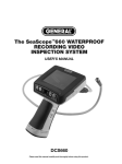
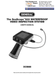
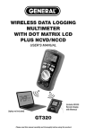
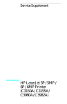
IN/OUT THERMOMETER
WITH WATERPROOF PROBE
USER’S MANUAL
AQ150
Please read this manual carefully and thoroughly before using this product.
TABLE OF CONTENTS
Introduction . . . . . . . . . . . . . . . . . . . . . . . . . . . . . . . . . . . . . . . . . . . . . . . . . . . . . . . . . . . . 3
Key Features . . . . . . . . . . . . . . . . . . . . . . . . . . . . . . . . . . . . . . . . . . . . . . . . . . . . . . . . . . . 4
What’s In the Blister Pack . . . . . . . . . . . . . . . . . . . . . . . . . . . . . . . . . . . . . . . . . . . . . . . . 4
Product Overview . . . . . . . . . . . . . . . . . . . . . . . . . . . . . . . . . . . . . . . . . . . . . . . . . . . . 5 – 6
Setup Instructions . . . . . . . . . . . . . . . . . . . . . . . . . . . . . . . . . . . . . . . . . . . . . . . . . . . 6 – 8
Activate the Thermometer . . . . . . . . . . . . . . . . . . . . . . . . . . . . . . . . . . . . . . . . . . . . . 6 – 7
Choose a Temperature Unit . . . . . . . . . . . . . . . . . . . . . . . . . . . . . . . . . . . . . . . . . . . 7
Mount the Display Unit . . . . . . . . . . . . . . . . . . . . . . . . . . . . . . . . . . . . . . . . . . . 7 – 8
Extend and Secure the Probe . . . . . . . . . . . . . . . . . . . . . . . . . . . . . . . . . . . . . . . . . 8
Operating Instructions . . . . . . . . . . . . . . . . . . . . . . . . . . . . . . . . . . . . . . . . . . . . . . . 9 – 11
Displaying Real-time Temperature . . . . . . . . . . . . . . . . . . . . . . . . . . . . . . . . . . . . . 9
Displaying MAX and MIN Temperatures . . . . . . . . . . . . . . . . . . . . . . . . . . . . . . . . . 9
Setting High and Low Temperature Alarms . . . . . . . . . . . . . . . . . . . . . . . . . 10 – 11
Specifications . . . . . . . . . . . . . . . . . . . . . . . . . . . . . . . . . . . . . . . . . . . . . . . . . . . . . . . . . 12
Maintenance Tips . . . . . . . . . . . . . . . . . . . . . . . . . . . . . . . . . . . . . . . . . . . . . . . . . . . . . . 13
Warranty Information . . . . . . . . . . . . . . . . . . . . . . . . . . . . . . . . . . . . . . . . . . . . . . . . . . . 13
Return for Repair Policy . . . . . . . . . . . . . . . . . . . . . . . . . . . . . . . . . . . . . . . . . . . . . . . . . 14
2
INTRODUCTION
Thank you for purchasing General Tools & Instruments’ AQ150 In/Out Thermometer with Waterproof
Probe. Please read this user’s manual carefully and thoroughly before using the product.
The AQ150 has two separate temperature sensors: one inside the display unit and the other inside a
remote probe at the end of a 10 ft. (3m) long detachable cable. The remote circuit can be configured
to sound an alarm when the temperature it senses rises above or falls below a set limit. This
technology makes the AQ150 suitable for three different kinds of service:
• Maintaining the water temperature of an aquarium. In this application, the display unit is
magnetically attached to the frame of the aquarium and the remote probe is attached by
suction cup to the inside of a glass wall below the water level. The high and low alarms
would both be set to keep the water temperature within a band that is healthy for fish.
• Monitoring food temperature. The dual alarms make it possible to track the temperature
of a refrigerated case or heating table. Magnets on the back of the display unit could be used
to attach it to a metal part of the case or table. The high temperature alarm would be used to
guarantee that cold beverages and cold or frozen food remain that way. Use of the low
temperature alarm would ensure that hot food remains above a certain temperature, keeping
it safe to eat.
• Comparing indoor and outdoor temperature. The cable of the remote probe is thin
enough to fit under a window. A front panel switch lets you toggle the display between
INT (interior) and EXT (exterior) measurements.
3
KEY FEATURES
• Displays ambient or remote (INT or EXT) temperature
• Tracks MAX and MIN temperatures
• High and low temperature alarms for remote circuit
• ºC/ºF button
• Backlit LCD and detachable cable of remote probe
• Foldaway stand and magnets on back of display unit
• Includes battery and mounting hardware
• CE approved
WHAT’S IN THE BLISTER PACK
The thermometer comes in a blister pack along with:
• A remote probe at the end of a detachable cable
• A suction cup for mounting the probe inside an aquarium or on a window
• A plastic bracket and screw for attaching the probe to wood
• Two Velcro strips for mounting the display unit
• (1) preinstalled “CR2032” battery with an activation tab
• This user’s manual
4
PRODUCT OVERVIEW
Fig. 1 shows the LCD and controls on the front of the AQ150. Fig. 2 shows the key areas and
components on the back of the unit.
1
2
3
4
Fig. 1. The controls and indicators
5
on the front of the AQ150
1. LCD. Display shown indicates that the
6
current (real-time) temperature sensed
by the remote (EXT) probe is 82.2°F.
2. Max/Min button. Switches display out
of real-time mode to show maximum and
minimum temperatures recorded since the
unit’s battery was installed or its memory was reset.
3. Ext/Int button. Toggles display between internal and external temperature sensors.
4. button. Used to arm and disarm alarm and set high and low temperature alarm limits.
5.
button. When pressed and held, turns display backlight on. When released, turns backlight off.
6. Remote temperature-sensing probe at the end of a detachable 10 ft. (3m) long cable.
5
8
Fig. 2. The back of the AQ150
9
7
7. Foldaway stand for table or desktop
mounting
8. Display unit Velcro mounting area
9. Mounting magnets
10. °C /°F button. Used to select displayed temperature
unit and set high and low temperature alarm limits
11. Alarm speaker
12. Battery compartment
10
11
12
SETUP INSTRUCTIONS
ACTIVATE THE THERMOMETER
If you are reading this, you have already removed the unit, the detachable probe, the suction cup and
the plastic bag of mounting hardware from the bubble-wrap bag. At this time, DO NOT remove the
twist tie keeping the 10-ft. probe cable in a neat bundle.
6
To activate the thermometer, open the battery compartment in the back of the unit (Fig. 2, Callout
12) by lifting the left side of the hinged door with your fingertip. Remove the battery activation tab. The
beeper will sound quickly four times. Discard the tab and swing the battery compartment cover shut.
CHOOSE A TEMPERATURE UNIT
Before proceeding, remove the protective plastic film covering the display. Then turn the unit over and
press the red °C /°F button (Fig. 2, Callout 10) to select a Celsius (°C) or Fahrenheit (°F) temperature
unit. °C is the default setting.
MOUNT THE DISPLAY UNIT
To leave the unit free to move on a horizontal surface, lift the foldaway stand on the back of the unit
(Fig. 2, Callout 7) by placing your fingertip in the recess adjacent to the Velcro mounting area.
To attach the unit to the metal frame of an aquarium, refrigerated case or heating table, use the
two magnets on the top edge of the back of the case.
To attach the unit to a wall or any non-metal surface:
1) Remove the two Velcro strips from the mounting hardware bag.
Do not separate them.
2) Remove the paper backing from one strip and press its exposed sticky side into the unit’s
recessed rectangular mounting area (Fig. 2, Callout 8).
3) Remove the paper backing from the other strip.
4) Press the unit against the wall at the desired position.
7
To detach the unit (to change the battery, change the temperature unit, or reset the high and/or low
alarm limits), grab it and pull until the two Velcro strips separate.
EXTEND AND SECURE THE PROBE
Remove the twist tie keeping the probe cable in a bundle. Extend the probe cable to the desired
length.
To install the remote probe in an aquarium,
1) Slide the probe tip through the hole in the base of the suction cup.
2) Press the suction cup firmly against the glass inside the aquarium about 4 in. (100mm) below
water level.
To attach the probe to the inside of a refrigerated case or heating table, or to the outside
of a window,
1) Slide the probe tip through the hole in the base of the suction cup.
2) Moisten the inside of the suction cup and press it firmly against the inside frame or glass of
the refrigerated case, heating table or window.
To attach the probe to a wooden outside window frame or apron,
1) Slide the probe into the channel of the supplied black plastic bracket. Push the probe until its
tip reaches the end of the channel.
2) Using the supplied Phillips-head wood screw, secure the bracket to the frame or apron.
8
OPERATING INSTRUCTIONS
DISPLAYING REAL-TIME TEMPERATURE
To display the ambient temperature at the display unit, press the Ext/Int button until INT appears at
the right of the readout. To display the temperature sensed by the probe, press the Ext/Int button
until EXT replaces INT.
DISPLAYING MAX AND MIN TEMPERATURES
Pressing the Max/Min button briefly (for less than 1 second) cycles through three readings: maximum,
minimum and real-time temperatures. After the unit is activated, the initial readout is the real-time
EXT temperature.
Press the Max/Min button once and the display will switch to the highest (maximum) temperature
recorded since the unit’s battery was installed or since the memory was reset. The term MAX will
appear, flashing, at the left of the display.
Press the Max/Min button again and the display will switch to the lowest (minimum) temperature
recorded since the unit’s battery was installed or since the memory was reset. The term MIN will
appear, flashing, at the left of the display.
Press the Max/Min button a third time and the display will return to showing the real-time INT or
EXT temperature.
To reset the Max/Min memory, press the Max/Min button and hold it for at least 1 second.
9
SETTING HIGH AND LOW TEMPERATURE ALARMS
Temperature alarms can only be set for the sensor in the external probe. You cannot set alarms with
the display unit mounted on a wall or frame because setting alarm levels requires access to the °C /°F
button on the back of the unit. Before proceeding, detach the unit by pulling it off the metal frame or
separating the Velcro mounting strips.
1. To set either or both alarms, begin by pressing the button and holding it for 3+ seconds.
This will cause the display to begin flashing a value, along with the non-flashing terms HIGH
and EXT. The term AL will also appear (not flashing), in the lower left corner. You now have
1 minute to set the high temperature alarm limit at any level within the remote probe’s range
of -58° to 158°F (-50° to 70°C) by following Step 2. If you do not wish to set the high
temperature alarm, skip ahead to Step 3 below.
2. To set the high temperature alarm limit, hold the unit in one hand in front of your face.
With your other hand, reach behind the unit and begin pressing the °C /°F button. Each press
of the button increases the alarm temperature level (as shown on the display) by 1.8° with
the display in °F mode and by 1° with the display in °C mode. To speed up the process by
increasing the temperature in multiple steps, press and hold the °C /°F button.
When the desired high temperature alarm level is displayed, press the button
to store the setting. The beeper will sound once and the display will begin to flash a value,
along with the terms LOW and EXT. You now have 1 minute to set the low temperature alarm
level at any value within the remote probe’s range of -58° to 158°F (-50° to 70°C). If you do
not wish to set the low temperature alarm, press the button again and skip ahead to
Step 4 on next page.
10
3. To set the low temperature alarm limit, follow the instructions in Step 2 on previous page,
subtituting “low” for “high” and “decreases/decreasing” for “increases/increasing.”
4. When the desired low and/or high temperature alarm level(s) is/are displayed, press the
button to store the setting(s).
Once you have stored the high and/or low alarm temperature level(s), the display will stop flashing and
resume showing the Int or Ext temperature it was showing when the alarm setting process began.
However, the term AL will remain in the lower left corner. Whenever the display is not flashing, the
button serves as the vehicle for arming and disarming the alarms. If AL appears on the display,
any alarms are armed. If it does not, any alarms are disarmed.
Note: If you set a high alarm limit that is below the real-time Ext temperature, the alarm will sound
within 10 seconds of storing the setting. The alarm will also sound if you set a low alarm limit that is
above the real-time Ext temperature.
To stop the alarm from sounding, press any button.
11
SPECIFICATIONS
Ambient Temperature Range:
Remote Temperature Range:
Measurement Accuracy:
Display Resolution:
Sampling Period:
Probe Cord Length:
Display Size:
Digit Height:
Dimensions:
Weight:
Power Source:
12
14° to 122°F (-10° to 50°C)
-58° to 158°F (-50° to 70°C)
±1°F (0.5°C) from -4° to 122°F
(-20° to 50°C); ±1.8°F (±1°C)
outside this range
0.1° (C or F)
10 seconds
10 ft. (3m)
1.88 x 0.82 in. (48 x 21mm)
5/8 in. (16mm)
2.9 x 2.1 x 0.7 in. (73 x 52 x 18mm)
3.76 oz. (106g)
1 “CR2032” battery (included)
MAINTENANCE TIPS
Although the sensor, probe and cable are waterproof, the display unit is NOT waterproof. Do not install
the display unit outdoors.
To clean the display unit, wipe it gently with a dry or damp cloth. Avoid using chemical cleaners.
To replace the battery, follow the instructions at the top of p. 7.
WARRANTY INFORMATION
General Tools & Instruments’ (General’s) AQ150 In/Out Thermometer with Waterproof Probe is
warranted to the original purchaser to be free from defects in material and workmanship for a period
of one year. Subject to certain restrictions, General will repair or replace this instrument if, after
examination, the company determines it to be defective in material or workmanship.
This limited warranty does not apply to damages that General determines to be from an attempted
repair by non-authorized personnel or misuse, alterations, normal wear and tear, or accidental
damage. The defective unit must be returned to General Tools & Instruments or to a Generalauthorized service center, freight prepaid and insured.
Acceptance of the exclusive repair and replacement remedies described herein is a condition of the
contract for purchase of this product. In no event shall General be liable for any incidental, special,
consequential or punitive damages, or for any cost, attorneys’ fees, expenses, or losses alleged to be
a consequence of any damage due to failure of, or defect in any product including, but not limited to,
any claims for loss of profits.
13
RETURN FOR REPAIR POLICY
Every effort has been made to provide you with a reliable product of superior quality. However, in the
event your instrument requires repair, please contact our Customer Service to obtain an RGA (Return
Goods Authorization) number before forwarding the unit via prepaid freight to the attention of our at
this address:
General Tools & Instruments
80 White Street
New York, NY 10013
212-431-6100
Remember to include a copy of your proof of purchase, your return address, and your phone number
and/or e-mail address.
14
NOTES
______________________________________________________________________
______________________________________________________________________
______________________________________________________________________
______________________________________________________________________
______________________________________________________________________
______________________________________________________________________
______________________________________________________________________
______________________________________________________________________
______________________________________________________________________
______________________________________________________________________
______________________________________________________________________
______________________________________________________________________
______________________________________________________________________
15
GENERAL TOOLS & INSTRUMENTS
80 White Street
New York, NY 10013-3567
PHONE (212) 431-6100 FAX (212) 431-6499
TOLL FREE (800) 697-8665
e-mail: [email protected]
www.generaltools.com
AQ150 User’s Manual
Specifications subject to change without notice
©2012 GENERAL TOOLS & INSTRUMENTS
NOTICE - WE ARE NOT RESPONSIBLE FOR TYPOGRAPHICAL ERRORS.
MAN#AQ150 9/25/12