1
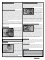
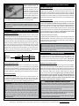
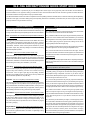
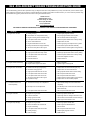
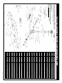
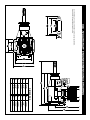
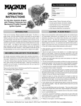
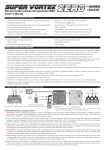
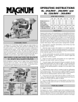
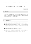
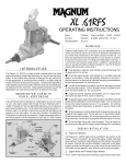
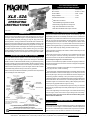
XLS .52A AIRCRAFT ENGINE
SPECIFICATIONS AND FEATURES
XLS .52A
AIRCRAFT ENGINE
OPERATING
INSTRUCTIONS
P/N 210760
INTRODUCTION
Thank you for choosing a Magnum XLS series aircraft engine. The XLS .52A
is a single cylinder, two-stroke engine incorporating ABC (Aluminum piston,
Chrome plated Brass sleeve) technology for long life, high power output
and easy break-in. The engine features a dual needle valve carburetor with
optional rear-mounted needle valve for precise fuel/airflow metering, dual
ball bearing-supported crankshaft, dual bushing-supported connecting rod,
and a high-flow quiet muffler. Your Magnum XLS series engine was designed
by expert engineers and built by master craftsmen using only the highest
quality materials and CNC machinery. These qualities provide the long life
and dependability you have come to expect from an engine of this caliber.
BECOMING FAMILIAR WITH YOUR ENGINE
If you are familiar with the operation of two-stroke model engines or just
can't wait to run your new engine, please read through the Quick-Start
Guide included. The Quick-Start Guide will help you get started right away
and also includes some good recommendations. We do recommend reading
through these Operating Instructions in their entirety to familiarize yourself
with the features and operation of your new engine. We have also included
a Troubleshooting Guide should you encounter any problems.
Please use the photos below to familiarize yourself with the components of
your new Magnum XLS series engine.
Displacement..................................................52ci (8.47cc)
Bore / Stroke..................................................22.4mm / 21.5mm
Practical RPM................................................2,200 - 18,000
Weight w/Muffler............................................17.4oz
Crankshaft Thread Size.................................1/4-28
l
ABC Piston and Sleeve
l
Dual Ball Bearing-Supported Crankshaft
l
Dual Bushing-Supported Connecting Rod
l
High-Flow Quiet Muffler for More Power
l
Rear-Mounted Needle Valve Option Included
CAUTION - PLEASE READ BEFORE USE!
Magnum XLS series model aircraft engines will consistently give you
dependable performance and reliability and will be a source of satisfaction
and pleasure if you follow these instructions as to the engine’s proper and
safe use. You alone are responsible for the safe operation of your engine,
so act sensibly and with care at all times. This Magnum XLS series model
aircraft engine is not a toy. It is a precision-built machine whose power is
capable of causing serious injury to yourself and others if abused or misused,
or if you fail to observe proper safety precautions while using it.
l Keep spectators, especially small children, at least 20 feet away from the
engine while it is running.
l Mount the engine securely in the aircraft or on a suitable engine test stand
to run the engine. Follow the mounting instructions in your aircraft's
instruction manual or on the plans for individual mounting recommendations.
Do not clamp the engine in a vise to test-run it.
l Use the recommended size propeller and follow the proper procedure for
mounting the propeller. Use the correct size wrench to tighten the propeller
nut. Do not use pliers.
l Inspect the spinner, propeller, and propeller nut on a regular basis, looking
for any signs of nicks, cracks or loosening.
l To stop the engine, adjust the throttle linkage to completely close the throttle
barrel and therefore cut off the fuel/air supply. You can also pinch the fuel
line to stop the engine, but only if it is accessible. Do not throw anything into
the spinning propeller or attempt to use your hands to stop the engine.
l While the engine is running, stand behind the engine to make any adjustments
to the needle valves. Do not reach over or around the propeller. Do not lean
toward the engine. Do not wear loose clothing or allow anything to be drawn
into the spinning propeller while the engine is running.
l If you need to carry your model while the engine is running, be conscious
of the spinning propeller. Keep the aircraft pointed away from you and others
at all times.
l Do not use a tight-fitting cowl over the engine. It can restrict air from flowing
over the engine, which could result in engine damage from overheating.
For proper cooling, the total cowl air-exit area should be 30% greater
than the total air-intake area.
*Due to running manufacturing
changes and improvements,
your engine may differ slightly
from that shown.
For product warranty information, please refer to the
warranty card provided with your engine.
Magnum XLS series engines are distributed exclusively by Global Hobby Distributors
All contents copyright © 2009, Global Hobby Distributors, August 2009
ENGINE INSTALLATION
Engine Orientation
Your XLS series engine can be orientated in any position on the firewall. Keep
in mind that when the engine is mounted inverted, carburetor adjustments
will need to be made differently and the fuel tank may need to be lowered.
(See fuel tank size and orientation to carburetor on the next page.)
Global Services l 18480 Bandilier Circle l Fountain Valley, CA 92708 l Phone: (714) 963-0329 l Fax: (714) 964-6236 l Email: [email protected]
1
Engine Bolts and Firewall Requirements
Rear Needle Valve Assembly Installation - Optional
The engine should be mounted to either a glass-filled nylon engine mount,
a machined aluminum engine mount, or an integrated hardwood beam
mount. Use only high-quality 6-32 or 4mm steel socket-cap screws and
related hardware to mount the engine to the engine mount. The firewall in the
aircraft should be aircraft grade 5-ply plywood no less than 1/4" thick and the
firewall should be reinforced to meet the torque and weight of the engine.
Your XLS Series engine comes with the needle valve preinstalled in the
carburetor. Also included is a rear needle valve assembly which can be
installed in place of the carburetor mounted needle valve assembly. By using
the rear needle valve assembly, adjusting the needle valve is safer because
it's further behind the spinning propeller.
Fuel Tank Size and Orientation to Carburetor
Ideally, the stopper in the fuel tank should be level with the high speed needle
valve or just slightly below it. Some models will only allow the fuel tank to be
mounted higher than the ideal location. A fuel tank that is positioned higher
than the ideal location usually doesn’t pose any problem except when it is
mounted excessively higher and/or is used in conjunction with an inverted
mounted engine or during extreme aerobatic flight. If you mount the engine
inverted, we strongly suggest lowering the fuel tank so the stopper assembly
is slightly below the high speed needle valve. Doing this will prevent fuel
from siphoning into the engine and flooding it. If you cannot lower the fuel
tank far enough, we suggest lowering it as far as can be allowed in your
particular application.
The size of the fuel tank used should be 10oz.~12oz., depending on the
model and the length of flights desired. Use of a 12oz. tank will provide
approximately 15 minutes of run time at full throttle. Use of a fuel tank any
larger than 12oz. can lead to excessive leaning of the engine during flight
and is not recommended.
Carburetor Installation
The carburetor is held in place using two socket-cap screws provided. Slide
the base of the carburetor into the
crankcase, being careful to keep
the carburetor perpendicular to
the front of the engine. Using
your thumb, push down firmly on
the carburetor so that the base of
the carburetor sets completely
into the crankcase. An o-ring is
installed on the carburetor throat
to seal the joint. While holding the
carburetor firmly down into place, install and GENTLY tighten the socket-cap
screws using the hex wrench provided.
WARNING Do not overtighten the socket-cap screws or you might strip
the threads in the carburetor, resulting in replacement of the carburetor.
Muffler Installation
The muffler is mounted to the engine using the two socket-cap screws, two
split washers and one of the two
gaskets provided. The second
gasket should be kept as a spare.
Tighten both screws firmly to
prevent the muffler from loosening
during flight. The exhaust cone
on the back of the muffler can
be adjusted to better match the
installation of your particular
application. To adjust the exhaust
cone, loosen the retaining nut, rotate the cone to the desired angle, then
tighten the retaining nut firmly while holding the axial bolt in place from the
front of the muffler. It is important to tighten the retaining nut firmly to
prevent the exhaust cone from loosening during flight.
2
To mount the rear needle valve
assembly, use an adjustable
wrench to unscrew and remove
the needle valve assembly from
the carburetor and to unscrew
and remove the plug from the
rear needle valve mount.
Carefully thread the needle valve assembly into the rear needle valve mount
and tighten it firmly, then carefully thread the plug into the carburetor and
tighten it firmly. Remove the two upper backplate mounting screws, then
install and tighten the two longer socket-cap screws and split washers
(included with the rear needle valve assembly) to secure the rear needle
valve assembly to the engine backplate. Connect the length of fuel tubing
provided between the chrome fuel nipples on the rear needle valve assembly
and the carburetor. The fuel pick-up line from your fuel tank should be
connected to the larger brass nipple on the rear needle valve assembly.
Carburetor Idle Stop Screw and Adjusting the Idle Speed
The idle stop screw holds the throttle barrel in the carburetor body and
also adjusts the closure of the
throttle barrel. We recommend
adjusting the idle stop screw to
allow the throttle barrel to close
completely. This will allow you
to adjust the idle speed via your
transmitter; therefore, you will
need to set up your transmitter throttle trim lever to keep the engine at a low
idle when the trim lever is centered, then to shut off the engine when the trim
lever is pulled all the way back. To adjust the idle stop screw, first loosen the
hex nut using an adjustable wrench, then loosen the idle stop screw (turn
counter-clockwise) to allow throttle barrel to close more, or tighten the idle
stop screw (turn clockwise) to make the throttle barrel stay open more.
When satisfied with the adjustment, tighten the hex nut firmly.
Throttle Arm Position
The throttle arm angle can be adjusted to better suit your particular
application. Using a 1.5 hex wrench, loosen grub screw in the side of the
throttle arm, then adjust the angle of the throttle arm either forward or
backward, and firmly tighten the grub screw.
Needle Valve Extension
If an extension is required to adjust the high speed needle valve, use a
1.5mm diameter wire of the necessary length (not included). Loosen the
grub screw in the side of the needle valve using a 1.5mm hex wrench, insert
the wire into the end of the needle valve, then tighten the grub screw firmly.
Propeller Installation
WARNING Before installing the propeller it must be balanced. Running
your engine using an out-of-balance propeller can lead to excessive vibration,
which will result in excessive stress and wear on both the engine and the
airframe. Balance the propeller using the method recommended by the
propeller manufacturer. Several products are available to properly balance
propellers. Ask your local retailer for more information about these items.
Global Services l 18480 Bandilier Circle l Fountain Valley, CA 92708 l Phone: (714) 963-0329 l Fax: (714) 964-6236 l Email: [email protected]
Using a 1/4" drill bit or a propeller
reamer, enlarge the hole in the
propeller hub to fit the crankshaft.
Slide the propeller onto the
crankshaft, up against the drive
washer, then slide the propeller
washer up against the propeller
and thread the propeller nut into
place. Tighten the propeller nut
firmly to secure the propeller into place. When tightening the propeller nut,
use an adjustable wrench or a 4-way wrench. Do not use pliers.
WARNING If you are installing a spinner onto your engine, the spinner
cone must not rub against the propeller. Allowing the spinner cone to
rub against the propeller could lead to propeller damage and eventual
propeller failure.
PROPELLER, GLOW PLUG AND FUEL
Propeller Recommendation
The diameter and pitch of the propeller needed for the XLS .52A engine will
vary greatly depending on the application the engine is used in. The weight,
drag, and the type of model and how you intend to fly it are all factors
in determining the correct size propeller to use. Experimentation will be
necessary to find the optimal size propeller for your particular application.
Ideally you want a propeller that the engine will turn in the 10,000 - 15,000
rpm range on the ground, yet power the aircraft sufficiently. Using a propeller
that is too small will cause the engine to run at too high an rpm. Using a
propeller that is too large will cause the engine to run at too low an rpm,
cause it to lug down too much and make tuning difficult. In both instances
this can lead to premature engine wear and eventual failure.
HIGH AND LOW SPEED NEEDLE VALVES
High Speed Needle Valve
The high speed needle valve is used to meter the air/fuel mixture at full
throttle. Turn the needle valve clockwise to lean the mixture or turn the
needle valve counterclockwise to richen the mixture. When you start the
engine for the very first time the needle valve should be turned in completely,
then backed out 2-1/2 turns. When you start the engine after that, leave the
needle valve in the same position it was in when you shut down the engine.
Low Speed Needle Valve
The low speed needle valve is preset from the factory for initial starting and
break-in. Do not adjust it until after the engine is broken in. The low speed
needle valve regulates the air/fuel mixture at idle and during transition from
idle to full throttle. Turn the needle valve clockwise to lean the mixture or
turn the needle valve counterclockwise to richen the mixture. The low speed
needle valve is preset from the factory, but minor adjustments may need
to be made after the engine is broken in. To reset the low speed needle
valve to the factory setting, follow these procedures:
l
Open the throttle barrel completely.
While holding the throttle barrel open, turn the low speed needle valve
clockwise GENTLY until it stops. From this point, while still holding the
throttle barrel open, turn the low speed needle valve counter-clockwise 3
full turns. This is the factory setting.
l
WARNING It is possible to adjust the low speed needle valve so lean
that the engine will not draw fuel. The low speed needle valve should not
need to be adjusted more than one full turn in either direction from the
factory setting. If the engine does not idle or transition, reset the low speed
needle valve to the factory setting.
Propeller Size Recommendations
Use for
Break-In
9x6
11 x 4 - 8
10 x 6
10 x 5 - 8
12 x 3 -6
STARTING PROCEDURE
Your XLS series engine can be started using an electric starter or it can
be started by hand. For safety and ease of starting, especially when the
engine is new, we recommend using an electric starter. The following
two procedures should be done with the power to the glow plug off.
Glow Plug Recommendation
Starting Using an Electric Starter
Glow plugs can make a big difference in the performance of your engine.
We recommend using a long-reach, hot heat-range glow plug intended
specifically for high-performance two-stroke engines. Do not use a cold
heat-range plug and do not use glow plugs that use an idle bar. This can lead
to erratic engine runs, difficult tuning and eventual engine wear and failure.
It's best to use an electric starter only when your engine as a spinner installed.
Prior to use, make sure that the electric starter is turning counter-clockwise.
When using an electric starter it is not necessary to prime the engine. The
starter turns the engine over fast enough that the engine draws fuel on its
own. Priming the engine prior to using an electric starter can cause the
engine to hydro-lock (flood). Turning the engine over with an electric
starter while the engine is flooded can cause extreme damage to the
engine and/or cause the propeller assembly to come loose. Turn the
propeller through the compression stroke one time by hand to check
for a hydro-locked state before applying the starter.
Fuel Recommendation
Fuel can make a big difference in the way your engine performs. We
recommend using a fuel containing 10%~20% nitro and 18%~20% castor
oil/synthetic oil blend lubricant. The same fuel can be used for both break-in
and normal running. Do not use a fuel containing less the 18% oil.
IMPORTANT We highly recommend that the first gallon of fuel run
through the engine contains either a castor oil/synthetic oil blend, or all
castor oil. Do NOT use an all-synthetic oil fuel for the break-in period.
After the first gallon of fuel, you can switch to an all-synthetic oil fuel, but
only if the fuel is of high quality. For example, some 'sport' all-synthetic
fuels use low-grade oils or oils with the wrong thermal properties (they
do not transfer heat well), and do NOT work well in Magnum engines.
If there is any question, it's always safe to use a castor oil/synthetic oil
blended fuel, regardless of brand, as long as the oil content matches what
is specified above.
WARNING ABOUT ENGINE HYDRO-LOCKING
If the engine becomes hydro-locked, do not force the propeller through the
compression stroke. The excess fuel should be expelled from the engine.
Completely close the high speed needle valve until it bottoms out, then
remove the glow plug from the cylinder head.
l
l With a rag over the top of the engine, turn the crankshaft several times,
using your electric starter or flipping the propeller by hand. The excess
fuel will be expelled out of the engine and into the rag.
l Check to make sure that the glow plug has not been fouled, then reinstall
it and reset the high speed needle valve.
Global Services l 18480 Bandilier Circle l Fountain Valley, CA 92708 l Phone: (714) 963-0329 l Fax: (714) 964-6236 l Email: [email protected]
3
Starting by Hand
OPTIMIZING THE MIXTURE SETTINGS
When starting the engine by hand always use a chicken stick or a heavy
leather glove. Never just use your bare hand or serious injury could result.
To make the engine easier to start by hand it should first be primed. This is
done by opening the throttle barrel completely and covering the tip of the
muffler with your finger. Fuel can then be drawn into the engine by 'pulling'
the propeller through the compression stroke 2-3 times. This will draw fuel
into the engine. After fuel begins to enter the carburetor, remove your finger
from the muffler and pull the propeller through the compression stroke once
to check for a hydro-locked condition.
BREAK-IN PROCEDURE
IMPORTANT Your XLS series engine is an ABC engine. The cylinder
sleeve is tapered at the top, causing severe resistance when the piston
moves through the top of the stroke. This is normal. When the engine
heats up to operating temperature, this resistance will decrease and the
proper clearance will be achieved. The break-in procedure will guide you
through the steps necessary to properly break in your new ABC engine.
The break-in process allows the engine parts to perfectly fit each other
and properly protect each part from premature wear. The engine should be
broken in using the type of fuel recommended in the Fuel Recommendation
section on page 3. Fuel containing only synthetic lubricants should not
be used during the break-in procedure. For the break-in procedure we
recommend mounting the engine into the aircraft it will be used in. This way
the muffler, fuel tank and throttle linkage can all be tested in combination
with the engine. If your aircraft uses a cowl, it should be removed during
the break-in procedure.
WARNING Be careful never to lean the engine out too much. Remember
that the lubricants for your engine are suspended in the fuel. If you lean out
the fuel mixture too much you will also be lowering the amount of lubricant
entering your engine. Less lubricant means more chance of your engine
overheating and possible engine failure.
Setting the High Speed Needle Valve
q 1) Start the engine and remove the power from the glow plug. Allow the
engine to warm up for about 30 seconds.
q 2) After the engine has warmed up, slowly lean the high speed mixture
until the engine reaches peak rpm. After reaching peak rpm, richen the
mixture slightly until an audible drop in rpm is heard. If you are using a
tachometer this should be between a 200~300 rpm drop.
q 3) With the engine running at full power, carefully lift the nose of the aircraft
about 45º into the air. The mixture should not become too lean, but you may
hear a slight increase in rpm. If the engine sags, or loses rpm when you
hold the nose up, the mixture is too lean. If this is the case, slightly richen
the mixture and follow the test once more.
IMPORTANT Rpm will increase about 10%~30% in the air. This is
due to the forward motion of the aircraft as it is flying. Because of this,
more air is entering the carburetor, at a higher force, which causes the
mixture to lean out. Additionally, as the fuel level in the fuel tank goes
down, fuel draw becomes more difficult for the engine, especially during
aerobatics, thus causing the mixture to go lean. It is imperative that you
set the mixture rich while on the ground to compensate for the leaning
tendencies that will happen in the air. Always watch the exhaust during
your flight. The engine should leave a noticeable white smoke trail at all
times. If there is no smoke trail, the engine is running too lean. You should
land immediately and reset the mixture.
q 1) Turn the high speed needle valve out 2-1/2 turns from the fully closed
position.
q 2) If you are using an electric starter to start the engine, follow the
procedure in the previous section on page 3. If you are starting the engine
by hand, follow that procedure in the previous section above.
q 3) Open the throttle barrel to approximately 1/4 throttle, then connect the
power to the glow plug. Start the engine using an electric starter or by hand.
If starting by hand you will need to vigorously flip the propeller through the
compression stroke several times before the engine will start.
q 4) Once the engine starts, open the throttle barrel to about 1/2 throttle.
You may need to lean the high speed needle valve in about 1/4 turn to keep
the engine running at half throttle.
q 5) After the engine has been running about 1 minute, remove the power
from the glow plug and slowly advance the throttle barrel to full throttle.
Adjust the high speed needle valve so that the engine is running very rich.
You should notice excessive white smoke coming from the exhaust. Let the
engine run for approximately 10 minutes then stop the engine.
q 6) Let the engine cool for approximately 10 minutes then restart it. Set
the high speed needle valve mixture to a slightly leaner setting, about 1/4
turn more in. Let the engine run for about 5 minutes at this setting, then stop
the engine and let it cool for approximately 10 minutes.
Setting the Low Speed Needle Valve
q 1) Start the engine and lean out the high speed needle valve as per the
previous steps. Close the throttle until the slowest reliable idle is reached.
Allow the engine to idle for about 15~20 seconds.
q 2) Quickly advance the throttle to full. If the engine just stops running as
soon as the throttle is advanced, the idle mixture is too lean. With the engine
stopped, richen the idle mixture about 1/8 of a turn.
q 3) Repeat steps 1 and 2 until the engine will transition from idle to full
throttle smoothly. Minor hesitation in the transition is normal.
q 4) If you quickly advance the throttle from idle to full and the engine seems
to be very rich during transition (i.e., lots of smoke coming from the exhaust),
the mixture is too rich. With the engine stopped, lean the idle mixture about
1/8 of a turn.
q 5) Repeat steps 1 and 4 until the engine will transition from idle to full
throttle smoothly. Minor hesitation in the transition is normal.
BASIC ENGINE MAINTENANCE
Avoid running the engine under dusty conditions. If you are in a dusty
environment we suggest using an air filter over the carburetor.
l
q 7) Repeat the procedure in step 6, while leaning the needle valve slightly
more each time. In all, you should run the engine about a total of 45 minutes
of actual running time. After 45 minutes of run-time the engine is ready
for flight. Fly the aircraft with the engine set as rich as possible, but with
adequate power to fly the aircraft. After each flight, lean the mixture slightly.
Continue to do this for about 5 flights. At this point the engine should hold a
good setting on the high speed needle valve and you can begin to fine tune
the needle valve settings to increase performance.
4
At the end of every flying day, purge the engine of fuel by disconnecting
the fuel line and allowing the engine to run dry of fuel.
l
Use a high quality after-run oil in the engine after you have purged the
engine of fuel. Inject the oil into the engine through the carburetor and through
the glow plug hole. Rotate the crankshaft several times to distribute the oil
throughout the engine. This will prevent the engine from forming rust.
l
Global Services l 18480 Bandilier Circle l Fountain Valley, CA 92708 l Phone: (714) 963-0329 l Fax: (714) 964-6236 l Email: [email protected]
XLS .52A AIRCRAFT ENGINE QUICK-START GUIDE
The following information is provided to get your new Magnum XLS series engine running right away with minimal effort. We have listed our
recommendations for fuel, propeller, starting procedures and other recommended accessories. Also included is general information about the
accessories needed for the engine that we hope you will find helpful.
This Quick-Start Guide should not be used as a replacement for the Operating Instructions included; rather, it should be used along with the Operating
Instructions. We highly recommend reading through the Operating Instructions to familiarize yourself with each part of the engine, along with the
proper procedures for engine break-in and tuning.
OUR RECOMMENDATIONS
QUICK-STARTING PROCEDURES
The following items are recommended for use with your Magnum XLS
series aircraft engine. These items are recommended for initial start-up and
running. Please read through the Operating Instructions for further details.
Engine Preparation
Fuel: Power Master 15% 2-Stroke Premium Sport Fuel Blend for Break-In
q 2) Install the muffler onto the engine using the hardware provided. The
muffler cone can be rotated to better suit the installation in your model. Be
sure to tighten the nut securely to prevent the muffler cone from loosening.
and for Normal Use
We suggest using Power Master brand fuels. Power Master fuel comes
in many different nitromethane contents that can be used in your XLS
series engine. Power Master fuels are blended using only high-quality
nitromethane, methanol, castor oil and synthetic lubricants to provide
high power output, along with easy starting and unmatched lubricating
and heat dissipation qualities.
Fuel Tank: Dubro 12oz. Fuel Tank (Product Number 412)
Dubro fuel tanks are a perfect match for your XLS series engine. This
size recommendation will give you about 10~15 minutes of run-time at full
throttle. Dubro fuel tanks are possibly the easiest fuel tanks to assemble
and maintain, and feature a chin at the base of the fuel tank that prevents
the fuel tubing from kinking when installed in your aircraft.
Glow Plug: Thunderbolt # 3 Glow Plug (Product Number 115559)
The Thunderbolt # 3 glow plug is designed to be used in high-performance
engines using fuels containing 10%~30% nitro content and in any
environment. It is a ‘hot’ type of glow plug for easy starting, excellent
transition and incredible top end. The glow plug is also very durable and
able to withstand repeated use, day after day.
Propeller: APC 10 x 6 Propeller (Product Number LP10060)
We have found that XLS series engines run best using APC brand props.
They are designed to be very efficient and run quiet at high rpm’s, and
they are also durable. Use this size propeller to break in your engine, then
change to the propeller that best suits your application. Use the guide in
the Operating Instructions to help you find the right size propeller.
Glow Starter: Magnum Glow Starter w/Meter (Product Number 237438)
The Magnum glow starter is an excellent choice for heating the glow plug.
It uses a Sub-C NiCD, includes a meter to determine the quality of your
glow plug, and it also includes a charger to recharge the battery. It’s a
very economical product to purchase and can be used with any engine
that uses a glow plug.
Engine Mount: Dave Brown Engine Mount (Product Number 4650)
The Dave Brown engine mount is a glass-filled reinforced nylon mount
that mounts to a plywood firewall in the model. It is lightweight, strong
and easy to install.
q 1) Mount the engine to the recommended engine mount. A wood beam
mount built into the airframe would also be sufficient.
q 3) Install a glow plug into the cylinder head, making sure to use the
copper gasket provided with the glow plug.
q 3) Install the propeller to the engine using the propeller nut and washer
provided. Tighten the nut securely using an adjustable wrench.
q 4) Connect the fuel lines from the fuel tank to the engine. The fuel
pick-up line should be connected to the fuel nipple on the carburetor and
the pressure line should be connected to the pressure nipple on the muffler.
Engine Starting
q 1) Carefully turn the high speed needle valve in completely until it stops,
then turn the needle valve out 2-1/2 turns. This is the mixture setting for
initial starting.
IMPORTANT Do not adjust the low speed needle valve at this time.
It’s factory-adjusted for the break-in process.
q 2) If hand starting, prime the engine by opening the throttle barrel
completely, placing your finger over the carburetor opening and flipping
the propeller through compression 2~3 times. If you will be using an
electric starter, do not prime the engine. The starter will turn the engine
over fast enough to draw fuel on its own.
q 3) Connect the glow starter to the glow plug. Open the throttle barrel
to about 1/4 throttle and start the engine. If you are starting the engine by
hand, you will need to vigorously flip the propeller several times before
the engine will start. Once the engine begins running, immediately turn
the high speed needle valve in about 1/4 turn to keep the engine running.
q 4) Advance the throttle to full while turning the high speed needle
valve in to keep the engine running. The engine should be producing a
very noticeable white exhaust from the muffler and sound like it is running
rough. Allow the engine to run only for about 5 minutes, then shut the
engine off.
q 5) Now that you have started your engine, it must be properly broken
in. Proper break-in will seat all of the moving parts, particularly the piston
and cylinder. This procedure takes about 20~30 minutes of run-time and
is highly recommended. An engine that is properly broken in will produce
more power, be more user-friendly and last much longer than an engine
that does not receive a break-in period. For this reason we highly
recommend following the break-in procedure detailed in the Operating
Instructions before running the engine further.
XLS .52A AIRCRAFT ENGINE TROUBLESHOOTING GUIDE
This troubleshooting guide has been provided to help you diagnose and solve most problems that you may encounter with your XLS series engine.
Most problems encountered can be solved by carefully following the problem-cause-solution sections below. If you cannot solve the problem using
this troubleshooting guide, please feel free to contact us using the information below.
Global Services
18480 Bandilier Circle
Fountain Valley, CA 92708
Phone (714) 963-0329
Fax (714) 964-6236
Email: [email protected]
For product warranty information, please refer to the warranty card provided with your engine.
PROBLEM
CAUSE
SOLUTION
1) Engine does not start
A) Failed glow plug
A) Replace glow plug with new one
B) Glow starter not charged and/or faulty
B) Fully charge glow starter and/or replace
C) Engine not being turned over fast enough
C) Use an electric starter to start engine
D) Low speed needle valve set too lean
D) Reset low speed needle valve to factory setting
E) Old or contaminated fuel
E) Replace with new fuel
F) Engine flooded with too much fuel
F) Remove glow plug and expel fuel from cylinder
G) Faulty fuel tank and/or stopper assembly
G) Check and/or replace fuel tank assembly
H) Air leak in fuel system and/or engine
H) Replace fuel lines and/or tighten all engine bolts
2) Engine does not draw fuel
A) Air leak in fuel system and/or engine
A) Replace fuel lines and/or tighten all engine bolts
B) High speed needle valve fully closed
B) Reset high speed needle valve to factory setting
C) Low speed needle valve set too lean
C) Reset low speed needle valve to factory setting
D) Fuel lines kinked
D) Check and straighten fuel lines
E) Defective fuel tank
E) Replace fuel tank
3) Engine vibrates excessively
A) Propeller out of balance
A) Balance propeller
B) Engine and/or engine mount loose
B) Tighten engine mounting bolts
4) Engine does not transition
A) Failed and/or wrong type glow plug
A) Replace with new recommended glow plug
B) Old and/or wrong type fuel
B) Replace with new recommended fuel
C) High speed needle valve set too rich
C) Set high speed needle valve to leaner setting
D) Low speed needle valve set too lean
D) Set low speed needle valve richer
E) Low speed needle valve set too rich
E) Set low speed needle valve leaner
F) Air leak in fuel system and/or engine
F) Replace fuel lines and/or tighten all engine bolts
G) Propeller too large
G) Replace with one size smaller propeller
5) Throttle barrel does not
A) Throttle servo linkage out of adjustment
A) Adjust throttle linkage to close throttle barrel close completely
B) Idle stop screw out of adjustment
completely
B) Turn idle stop screw counter-clockwise until throttle barrel closes fully
C) Low speed needle valve set too lean
C) Set low speed needle valve richer
6) Engine overheats
A) Engine running too lean
A) Richen high speed needle valve
B) Cowl too restrictive
B) Open larger vents in cowling to allow air to exit
C) Wrong type of fuel used
C) Use fuel with recommended oil content and type
D) Engine not fully broken in
D) Allow engine further break-in time
7) Engine stops abruptly
A) Engine running too lean
A) Richen high speed needle valve
B) Piston and sleeve out of tolerances
B) Return engine to Global Services
C) Engine overheating
C) See # 6 above
D) Low speed needle valve set too lean
D) Set low speed needle valve richer
E) Failed glow plug
E) Replace glow plug with new one
F) Fuel tank empty
F) Refill fuel tank
284220
284222
284221
281160
281242
281154
281244
282002
283023
281240
281799
281160
281720
281159
281155
284225
281798
281901
281166
284206
281903
280201
282452
281800
280110
280201
280713
281151
281154
281155
281159
281160
281163
281166
281168
281240
281242
281244
281245
281246
281265
281306
281420
281601
281715
281720
281798
281799
281800
281901
281903
282002
282004
282130
282159
282201
282310
282401
282412
282452
282501
282608
283022
283023
284206
284220
284221
284222
284223
284225
284226
284227
284228
284229
284230
284231
ORDER #
46609
40228
S52204
400160
S91225
S91109
40120
80841
91130
12862
46871F
S40119
S40219
S40873F
S40813
S40901
S40863
28123
40110
40134
120616
S40120
S15860
S15861
S40874F
12833
12847
12819
12114
46814A
S32868F
46866
46810F
40816
40845
46845F
91137
46837F
S40801F
S40803F
12830
S52103X
S52112
S52203
S52213
S52101
S52210
S52111
S52102
S52601X
S52604X
S52416
REFERENCE #
Muffler Gasket
Propeller Nut and Washer
Connecting Rod
Sleeve Index Pin
Drive Washer Spacer
Ball Bearing - Front
Cylinder Head Mounting Bolts (6)
Lock Washers (2)
Lock Washer
High Speed Needle Valve Seat - Complete
Rear Needle Valve Mount Plug
Carburetor Retaining Bolts (2)
Drive Washer
Rear Needle Valve Mount Only
Throttle Barrel
Bolt Set - Cylinder Head and Backplate
Carburetor Body with Spray Bar
Rear Needle Valve Mounting Bolts (2)
Ball Bearing - Rear
Backplate Mounting Bolts (4)
Muffler Axial Bolt with Nut
Muffler Mounting Bolts (2)
High Speed Needle Valve Assembly - Complete
High Speed Needle Valve with O-Ring
Rear Needle Valve Assembly - Complete
High Speed Needle Valve Detent Spring
Needle Valve Seat/Plug Gasket
Fuel Nipple with Gasket
Fuel Nipple without Gasket
Throttle Barrel Spring
Carburetor Plug
Throttle Arm
Low Speed Needle Valve with O-Ring
Carburetor Base O-Ring
Low Speed Needle Valve O-Ring
High Speed Needle Valve O-Ring
Fiber Washer
Idle Stop Screw with Nut
Carburetor Assembly - Complete
Carburetor and Rear Needle Valve Assemblies
High Speed Needle Valve Seat
Cylinder Head
Cylinder Head Gaskets (2)
Piston and Sleeve Set
Wrist Pin and Retainer Set
Crankcase
Crankshaft
Backplate Gasket
Backplate
Muffler - Complete
Muffler Middle
Gasket Set - Cylinder Head and Backplate
DESCRIPTION
XLS .52A AIRCRAFT ENGINE EXPLODED PARTS VIEW
281151
281240
282159
282501
281168
281265
281903
281246
280110
280713
Replacement parts can be ordered directly from your local Magnum engine
hobby retailer. If your hobby retailer does not stock Magnum engines,
you can order replacement parts direct from us.
281420
282002
284223
Global Services
18480 Bandilier Circle, Fountain Valley, CA 92708
281160
284228
282004
284226
281800
284230
282130
282310
282401
282608
281715
284227
Phone: (714) 963-0329 / Fax: (714) 964-6236
Email: [email protected]
281306
281160
281601
281715 281163
284229
284231
281245
282412
282201
283022
Revision 3 August 2009
XLS .52A AIRCRAFT ENGINE DIMENSIONAL DRAWING
Use this drawing to help you determine engine mounting requirements.
Drawing is not to scale and is generic in nature.
XLS
F
E
D
C
B
A
1-1/8"
11/16"
3-1/2"
2-7/8"
4-3/4"
3-1/2"
3-3/8"
N
M
L
K
J
I
H
7/16"
1-3/4"
1-7/16"
1-1/16"
2-1/16"
1-3/4"
1-7/16"
DIMENSIONS
G