1
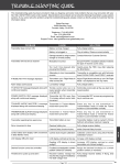
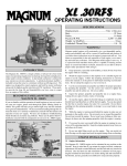
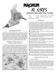
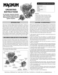
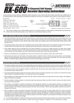
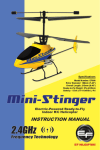
Fail Safe Programming, continued....
Fail Safe Programming
The Fail Safe function automatically moves the servos to a predetermined position in the event that the signal between
the transmitter and the receiver is interrupted, whether due to signal degradation or to low transmitter battery. Several
different setting options are available. The Fail Safe function can be set to Hold the servos in the last position they were
in when the signal was lost, or each of the servos can be set to move to a custom position when the signal is lost. For
example, the throttle servo moves to the Brake Side to engage the brakes and stop your model. If you're driving a
gas- or glow-powered boat, the Fail Safe function could be set to lower the throttle to idle and turn the rudder slightly
left or right so that the boat will continue in slow circles.
3) Press the ENTER key, then scroll UP or DOWN to choose the desired
Receiver Battery Fail Safe Voltage value.
F/S B-F/S setting range is 3.5v to 7.4v. The default setting is OFF.
In addition, a Receiver Battery Voltage Fail Safe function is available which allows you to set a custom voltage that the
Receiver Battery Fail Safe function will Activate at. This is useful if you're using servos with a higher than normal current
draw that might run out of power before the receiver does.
IMPORTANT: The Fail Safe function will NOT OPERATE if the receiver loses power. It will operate only if the
transmitter and receiver signal is interrupted or if the transmitter loses power.
The 92011 (RX-462) 2.4GHz FHSS-4T 4-Channel receiver is a Super Response, Telemetry receiver that is used with
the Airtronics MT-4 2.4GHz FHSS-4T transmitter. This receiver supports Airtronics Telemetry and features an extremely
low latency time and high frame rate, which makes you feel more connected to your model than ever.
The receiver will operate down to 2.5 volts, however, the minimum operating voltage of most servos is higher
than that. The Receiver Battery Fail Safe Voltage should be set to a value that will allow all of your servos to
operate. You will need to check your servo's specifications to determine the minimum voltage required for the compliment
of servos you're using.
Setting the Fail Safe
Fail Safe settings can be programmed for each of the four channels individually. In addition, Fail Safe settings are
Model-specific, meaning you can have different Fail Safe settings for each Model in memory. The Fail Safe settings will
be retained even if the transmitter loses power or if the transmitter and receiver must be paired again. Three Fail Safe
options can be programmed from your MT-4 2.4GHz FHSS-4T transmitter:
FREE - Fail Safe is disabled for this channel. Servos can move freely when the signal is lost.
HOLD - When Fail Safe Activates, the servo will be held in the last position it was in when the signal was lost.
% (PERCENTAGE) - When Fail Safe Activates, the servo will travel to the programmed position when the signal is lost.
92011
2.4GHz FHSS-4T
(RX-462) 4-Channel Telemetry
Receiver Operating Instructions
In addition to providing Telemetry readings for two temperature sources, RPM and receiver battery voltage, when used
with an electric-powered vehicle, the 92011 (RX-462) receiver is capable of reading the voltage of your vehicle’s motor
battery. This allows you to monitor the motor battery’s voltage in real-time during use.
This receiver is currently compatible only with the Airtronics MT-4 2.4GHz FHSS-4T transmitter. It is not compatible
with Airtronics 2.4GHz FHSS-2 or FHSS-3 transmitters. In addition, due to differences in the implementation of
2.4GHz technology among different manufacturers, this receiver is not compatible with any other transmitter brands.
For compatibility information with new Airtronics 2.4GHz surface transmitters released after this receiver, please visit
your local Airtronics retailer or visit our website at www.airtronics.net.
receiver features diagram and specifications
Voltage Connector
Fuse
Bind Button
Coaxial Cable
1) From the Top Screen, press the ENTER key to open the Programming
Menu list.
Auxiliary 2 (CH 4)
Auxiliary 1 (CH 3)
Throttle/ESC (CH 2)
Steering (CH 1)
2) Scroll UP or DOWN to highlight the F/S menu, then press the ENTER
key. The F/S menu will be displayed and [ST] : FREE will be highlighted.
Bind LED
Telemetry Inputs
To
Motor Battery
= Signal
= Positive
= Negative
Model: 92011 (RX-462) Telemetry
Frequency/Modulation: 2.4GHz/FHSS-4T
Nominal Input Voltage: 4.8v ~ 7.4v
Weight: 0.34oz (9.6gr)
Dimensions: 1.43 x 1.04 x 0.64in (36.2 x 26.5 x 16.3mm)
Fail Safe Support: Yes (All Channels Programmable)
Receiver Battery Fail Safe Support: Yes (3.5v ~ 7.4v)
3) Scroll UP or DOWN to highlight the desired channel you would like to
change the Fail Safe option for.
This receiver operates on the 2.4GHz frequency band. The 2.4GHz connection is determined by the transmitter
and receiver pair. Unlike ordinary crystal-based systems, your model can be used without frequency control.
4) Press the ENTER key, then scroll UP or DOWN to choose the desired
Fail Safe option for that channel. If you choose to program a % value,
see step 5 below.
Included with the receiver are rubber dust boots that we recommend installing into any empty receiver channel
slots and Telemetry Sensor inputs to keep out dust, debris, oil, etc.
2.4GHz frequency band precautions
The 2.4GHz frequency band may be used by other devices, or other devices in the immediate area may cause
interference on the same frequency band. Always before use, conduct a bench test to ensure that the servos operate
properly. Also, conduct checks with the transmitter as distant as possible from your model.
l
F/S setting range is FREE, HOLD, or %. The default setting is FREE.
The response speed of the receiver can be affected if used where multiple 2.4GHz radio controllers are being used,
therefore, carefully check the area before use. Also, if response seems slow during use, stop your model immediately
and discontinue use.
l
5) To program a Fail Safe percentage value, move the control the amount
you want the servo to move to when the Fail Safe function Activates
and HOLD it in that position, then press and HOLD the ENTER key
until an audible tone sounds. The percentage and direction the servo
will travel will be displayed. For example, to set the Throttle Brake to
engage when the Fail Safe function Activates, push the throttle trigger
toward the Brake side the desired amount, HOLD the throttle trigger in
that position, then press and HOLD the ENTER key. The percentage value
programmed will be indicated by two hash marks on the Servo Monitor.
If the 2.4GHz frequency band is saturated (too many transmitters on at once), as a safety precaution, the radio
control system may not Bind. This ensures that your radio control system does not get hit by interference. Once the
frequencies have been cleared, or the saturation level has dropped, your radio control system should be able to Bind
without any problems.
l
receiver precautions
6) Check to ensure your Fail Safe settings are working properly prior to running your model. For safety, it's preferable
to have someone hold your model. To check the Fail Safe settings, make sure that both the transmitter and receiver
are turned 'ON', then, while someone is holding your model, turn the transmitter 'OFF'. The servos should react
correctly based on the Fail Safe options chosen.
The receiver antenna consists of a coaxial cable and a reception wire (the thin tip at the end of the coaxial cable).
When you mount the receiver antenna, do not bend the reception wire. Reception performance decreases if the
reception wire is bent.
l
The antenna wire is delicate, therefore, handle with care. Do not pull on the antenna wire with force. Do not cut or
extend the antenna wire.
l
Setting the Receiver Battery Voltage Fail Safe Function
The Receiver Battery Voltage Fail Safe function allows you to set a custom voltage that the Receiver Battery Voltage
Fail Safe function will Activate at. When your receiver battery voltage drops to the programmed voltage, the throttle
servo will move to the predetermined position you programmed in step 5 in the Setting the Fail Safe section above. If
this occurs, recharge or replace your receiver batteries.
If FREE or HOLD is chosen for the Throttle channel, you cannot Activate the Receiver Battery Voltage Fail Safe
function. A % value must be chosen for the Throttle channel to be able to program and use the Receiver Battery
Fail Safe function.
2) From within the F/S menu, press the ENTER key, then scroll DOWN
to highlight [B-F/S] OFF.
Airtronics is Distributed Exclusively in North America by:
Global Hobby Distributors
18480 Bandilier Circle
Fountain Valley, CA 92708
Features and Specifications are Subject to Change Without Notice.
All contents © 2011 Airtronics, Inc.
All Rights Reserved. Revision 1-08.02.2011
Continued on Next Page
The antenna wire should be installed into a vertical plastic tube per your particular model's
assembly instructions. Keep the receiver antenna as far away from the motor, battery and ESC
as possible.
Antenna
Reception Wire
l
Telephone: (714) 963-0329
Fax: (714) 964-6236
Email: [email protected]
http://globalservices.globalhobby.com
http://www.airtronics.net
1) Follow steps 1 through 5 in the Setting the Fail Safe section above to
program a Throttle Fail Safe percentage value.
—5—
The coaxial cable (the thicker portion of the antenna) can be bent into gentle curves, however,
do not bend the coaxial cable acutely, or repeatedly bend it, or the antenna core can be damaged.
l
—6—
There is a danger of runaway operation if connectors shake loose during use. Make sure that
the receiver, servo(s), and switch connectors are securely fitted.
l
Coaxial Cable
Antenna Tube
The receiver is susceptible to vibration, shock, and moisture. Take appropriate measures to
protect against vibration and moisture. Failure to take appropriate measures could result in
runaway operation or damage to the receiver. We suggest wrapping the receiver in shockabsorbing foam or securing it with double-sided foam tape when installing it into your model.
l
l
l
When installing the receiver and routing the receiver antenna wire, avoid contact with any carbon or metal chassis
components. Contact between metal parts on a model can result in electrical noise, which can adversely effect
receiver performance and possibly result in runaway operation and damage to your model.
With electric-powered models, be sure to fit any brushed motors with a noise suppression capacitor. Without a noise
suppression capacitor, excessive electrical noise generation can cause runaway operation and/damage to your model.
—1—
general safety precautions
changing the servo mode setting, Continued....
telemetry sensor connections
Be certain to read these Operating Instructions in its entirety.
l
‘Safety First’ for yourself, for others, and for your equipment. Your model can cause serious damage or injury, so
please use caution and courtesy at all times.
l
Observe all the rules of the field, track or lake where you operate your radio control equipment.
l
If at any time during the operation of your model, should you feel or observe erratic operation or abnormality, end your
operation as quickly and safely as possible. DO NOT operate your model again until you are certain the problem has
been corrected. TAKE NO CHANCES.
The 92011 (RX-462) receiver features inputs for two Temperature Sensors and one RPM Sensor, in addition to the
Voltage Sensor that can read your receiver battery’s voltage or your motor battery’s voltage.
The receiver supports the use of two different Temperature Sensors at the same time, in addition to the RPM
Sensor. These sensors are available separately. For more information, visit your local Airtronics retailer or
visit our website at www.airtronics.net. Only Airtronics Telemetry Sensors are compatible.
l
The range of the Telemetry System is approximately 260 feet (80 meters), although the range can vary based on
many environmental factors. Use the Telemetry Signal Indicator on the transmitter to determine the quality of the signal.
Do not expose the receiver to water or excessive moisture. Waterproof the receiver and servos by placing them in a
water-tight radio box when operating R/C model boats.
IMPORTANT: For information about using the Telemetry system, refer to the pertinent sections in your MT-4
2.4GHz FHSS-4T transmitter's Operating Manual.
l
If you have little to no experience operating R/C models, we strongly recommend you seek the assistance of
experienced modelers or your local hobby shop for guidance.
l
Turn the transmitter 'ON' first, then turn the receiver 'ON'. After using your model, turn the receiver 'OFF' first, then
turn the transmitter 'OFF'. It can be dangerous if you activate the components in reverse order as the servos may
start up inadvertently.
Plugging the Telemetry Sensors into the Receiver
l
Before use, double-check that the transmitter and receiver batteries have sufficient power.
l
During use, hold the transmitter so that the antenna is orientated as close to vertical as possible at all times. This
provides the best RF signal between the transmitter and the receiver. You should never point the antenna directly at
your model, nor should you ever 'follow' your model with the antenna, as this results in a weakened RF signal.
l
receiver Connections and Mounting
Use the diagram below to make the servo and/or ESC, switch harness and battery connections to the 92011 (RX-462)
receiver.
The 92011 (RX-462) receiver's Nominal Input Voltage is 4.8 ~ 7.4 volts. A 2 cell Li-Po or 2 cell Li-Fe/A123 battery
pack can be used to power the receiver without the use of a voltage regulator. In addition, this allows you to take
advantage of the higher torque and speed provided by using 7.4 volt digital servos. Only use a 2 cell Li-Po or 2 cell
Li-Fe/A123 battery pack if your servos are rated to handle the higher voltage.
1) Use your fingernail to carefully pry up and remove the plastic dust cover from over the Telemetry Sensor inputs
on the receiver.
2) Plug the Telemetry Sensor(s) into their respective inputs in the receiver. The Temperature Sensor can be plugged
into either the TEMP 1 or the TEMP 2 input and the RPM Sensor is plugged into the RPM input. The input plugs
are indexed so they can be plugged in only one direction.
Make sure to push the input plugs firmly into their inputs in the receiver to ensure a good connection. When
routing sensor wires inside your model, be careful that they cannot come into contact with any moving parts or
can be damaged in the event of a crash. The sensor wires should be securely mounted and protected against damage.
Reading Receiver Battery Voltage
The 92011 (RX-462) 2.4GHz FHSS-4T 4-Channel receiver can either read your receiver battery’s voltage or your motor
battery’s voltage, depending on how you install the voltage plug.
To read your receiver battery’s voltage, plug the voltage connector into an empty channel slot in the receiver. If all four
channel slots are occupied by a servo, plug a Y-harness into an Auxiliary channel, then plug your auxiliary servo into
one end of the Y-harness and the voltage connector into the other end of the Y-harness.
Reading Motor Battery Voltage
The receiver should be mounted as far away from any electrical components as possible.
To read your motor battery’s voltage, carefully solder the end of the wire harness included with your receiver to the
positive terminal of your ESC, then plug the wire harness into the voltage connector.
The antenna wire should be installed into a vertical plastic tube per your particular model's assembly instructions.
l
desired channel you would like to change the Servo Mode option for.
Choose from either [ST] : NOR (Steering), [TH] : NOR (Throttle), [A1] :
NOR (Auxiliary 1) or [A2] : NOR (Auxiliary 2).
3) Press the ENTER key, then scroll UP or DOWN to choose the desired
Servo Mode option for that channel.
SERVO MODE setting range is NOR, SHR and SSR. The default setting
is NOR.
SHR and SSR Servo Modes should only be used with Digital servos.
While the SHR Servo Mode can be used with any Digital servo, the
SSR Servo Mode should only be used with Airtronics SRG Digital servos.
binding the transmitter and receiver
The Binding function allows you to 'Bind' the transmitter and receiver pair. When new, it is necessary to pair the
transmitter and receiver to prevent interference from transmitters operated by other users. This operation is referred
to as 'Binding'. Once the Binding process is complete, the setting is remembered even when the transmitter and
receiver are turned 'OFF'. Therefore, this procedure usually only needs to be done once.
Before beginning the Binding process, connect your servos and receiver battery pack to the receiver. For more
information, see the Receiver Connections and Mounting section on page 2. Both the transmitter and the
receiver should be turned 'OFF' to begin the Binding process.
1) Turn the transmitter 'ON'. The Top Screen will be displayed.
We suggest Binding the transmitter and receiver and making all receiver connections to check for correct operation
prior to mounting the receiver in your model. See the Binding the Transmitter and Receiver section on page 4.
l
l
2) From within the BIND menu, scroll UP or DOWN to highlight the
2) Press the ENTER key (Push-Button Rotary Dial) to open the Programming Menu list, then scroll UP or DOWN to
highlight the SYSTEM menu.
Negative Battery Wire
To protect the receiver from vibration and other damage, we recommend wrapping the receiver in shock absorbing
foam or using double-sided foam tape when installing it in your model.
Voltage Connector
l
3) Press the ENTER key to open the SYSTEM menu, then scroll DOWN
to highlight the BIND menu. Press the ENTER key to open the BIND
menu.
Motor Wires
IMPORTANT: The receiver battery can be plugged into any channel slot to power the receiver. To utilize all
channels and a separate receiver battery, a Y-Harness (not included) must be used. See diagram below.
Positive Battery Wire
If you're using an Electronic Speed Control with BEC circuitry, verify that it reduces the voltage to between 4.8
and 7.4 volts before making your connections and turning your radio control system 'ON'.
Verify that [RF MODE]: FH4T is displayed. If it isn't, change the Modulation Type to FH4T. For more information,
see the Changing the Modulation Type section on page 54 of your MT-4 2.4GHz FHSS-4T transmitter's
Operating Manual.
Throttle Connector
ESC On/Off Switch
If the voltage connector is not connected to the positive terminal of your ESC, plug the voltage connector into
an empty channel slot in your receiver. If the receiver cannot detect voltage an alarm will continuously sound.
4) Scroll UP or DOWN to highlight the [ENTER] command.
changing the servo mode setting
The Servo Mode setting can be changed to suit the type of servos you're using with your receiver. For example,
using the SHR setting with Digital servos will increase the servo's response time, even above the manufacturer's
stated specification. If you're using Airtronics SRG Digital servos, you can use the SSR setting for the fastest response
time. The combination of using Digital servos and using the correct Servo Mode setting results in the ultimate feel and
response, making you feel more in control of your model than ever.
5) While holding down the Bind Button on the receiver, turn the
receiver 'ON'. The Bind LED on the receiver will flash slowly. After
approximately 2 seconds, release the Bind Button. The Bind
LED on the receiver will continue to flash slowly.
The following Servo Modes can be programmed from your MT-4 2.4GHz FHSS-4T transmitter:
*Use Airtronics 97020Z Y-Harness.
Do NOT use servos rated for 4.8 or 6.0 volts with a 2S Li-Po or 2S Li-Fe/A123 receiver battery pack or damage
to the servos could result.
As a safety precaution, set your model on a stand so the wheels are off the ground before turning on your radio
control system or connecting your motor for the first time.
Bind LED Condition Indicator
The Bind LED on the receiver can be used to determine receiver condition at a glance. The Bind LED will alert you to
various receiver conditions, as shown in the table below.
LED COLOR
LED CONDITION
LED CONDITION DESCRIPTION
Blue
ON
Receiving RF Signal
Blue
Slow Flash
Binding Operation
Blue
Flash
Receiving Signal Command
Green
ON
Telemetry RPM Sensor Connected and Receiving Input
—2—
NORMAL - Use with any brand of Analog or Digital servos.
SHR - Use with any brand of Digital servos only. DO NOT USE WITH ANALOG SERVOS!
SSR - Use with Airtronics SRG Digital servos only. DO NOT USE WITH ANALOG SERVOS OR ANY OTHER TYPE OR BRAND OF DIGITAL SERVOS!
Use the tip of a non-conductive instrument to hold down the Bind Button on the receiver. Do NOT use a sharp object!
WARNING: If you're using Analog servos in your model, DO NOT use SHR or SSR Servo Mode options for that
channel. Use the NOR (Normal) Servo Mode with Analog servos. Using SHR or SSR Servo Mode options with
Analog servos can result in poor performance or even damage to the servos or the receiver! In addition, not all ESCs
are compatible with SHR or SSR Servo Modes. If your ESC does not operate correctly, change the Throttle Channel
Servo Mode setting to NOR (Normal).
We recommend that you choose your desired Servo Mode options
prior to Binding the transmitter and receiver, since Servo Mode
option changes will not take effect immediately. If you change the Servo
Mode after Binding the transmitter and receiver, you must Bind the transmitter
and receiver a second time to initialize the changes.
7) After the Bind LED on the receiver goes out, press the ENTER key a second time. The Bind LED on the receiver
will illuminate solid blue and LED 2 on the transmitter will go out, indicating that the Binding procedure is complete
and a Telemetry connection has been made.
8) Move the steering wheel and throttle trigger to verify that the servos are operating normally, then press and
HOLD the Back/Cancel key to return to the Top Screen.
Changing the Servo Mode Setting
When the Binding procedure is successful, the Bind LED on the receiver and LED 1 on the transmitter will illuminate
solid blue. If the Bind LED on the receiver is flashing rapidly or is not illuminated at all, the transmitter and receiver
are not paired. In this case, turn both the transmitter and receiver 'OFF', then repeat the Binding procedure again.
1) From within the SYSTEM menu, scroll UP or DOWN to highlight the
BIND menu.
—3—
6) Press the ENTER key. The [ENTER] command will begin to flash and
the Bind LED on the receiver will flash rapidly, then go out.
Continued on Next Page
—4—