1
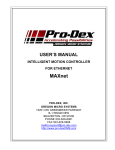
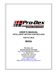
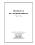
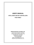
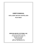
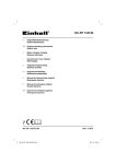
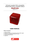
Produkt-Datenblatt, tech. Daten
Pro-Dex OMS Motion-Control
Kontakt
Technischer und kaufmännischer Vertrieb, Preisauskünfte, Angebote, Test-Geräte, Beratung vor Ort:
Tel: (0 89) 89 01 66-0
FAX: (0 89) 89 01 66-77
Aus dem Ausland:
Tel: ++49 - 89 - 89 01 66-0
FAX: ++49 - 89 - 89 01 66-77
E-Mail: [email protected]
Internet:
www.meilhaus.com/pro-dex
Web Kontakt-Formular:
www.meilhaus.com/kontakt
Per Post:
Meilhaus Electronic GmbH
Fischerstraße 2
D-82178 Puchheim
MEsstechnik fängt mit ME an.
www.meilhaus.com
Erwähnte Firmen- und Produktnamen sind zum Teil eingetragene Warenzeichen der jeweiligen Hersteller. Preise
in Euro zzgl. gesetzl. MwSt. Irrtum und Änderung vorbehalten.
© 2010 Meilhaus Electronic bzw. Icron.
ME-Cover_fuer_ProDex 1
16.11.2010, 9:08:41 Uhr
MAXnet
Pg. 1
MAXnet
Ethernet 5-Axis Motion Controller
FEATURES
Ethernet or RS232 Communications
•
•
Ethernet utilizes standard TCP/IP protocol.
RS232 Baud rate = 9600 to 115.2K
•
Delivers exceptional servo control on multiaxis applications.
Identical outcomes when utilizing one or all
axes of motion.
Configurable PID filter with feed forward
coefficients.
Control signals
•
PID update rate of 122 μs on all 5 axes
•
•
266 MHz, 32-bit RISC processor
•
Updates all signals and data points providing
superior application control.
Controller I/O Capabilities
•
•
•
•
Each axis has +Limit, -Limit, Home, Auxiliary
out, and axis control out.
8 General purpose bi-directional TTL I/O
1 General purpose analog output with 16 bit,
+/-10 VDC input (in addition to axes output).
2 Channels of general purpose analog input
with 16-bit (+/-10 VDC)
Motion Feedback
•
•
Each axis has an incremental encoder input
Quadrature Encoder Feed back up to 16 MHz
on all encoder inputs.
Sophisticated Control Functionality
•
•
•
•
•
•
16 bit DAC analog resolution.
Step pulses from 0 to 4,194,303 steps per
second (+/- 0 steps).
Backlash compensation.
Custom, parabolic, “S”-Curve & linear trajectory
profiles.
Real time encoder position capture.
S-Curve with 4-quadrant jerk parameters.
Pro-Dex, Inc.
•
•
Single 100-pin SCSI type connector for high
density signal connection.
8 “user definable” digital I/O.
Analog out per each axis can be used as general
purpose when axis is configured for Step control.
ADDITIONAL FEATURES
-
Small form-factor, 4in. x 6.5in.
Stand-alone capability
Custom Power-up Defaults
Non-Volatile Macro Storage
Patented technology to minimize torque ripple and
velocity modulation
Internal Watchdog timer for safety
Slip & Stall detection with encoder feedback
Linear/Circular interpolation
Constant and variable velocity contouring (all axes)
Single-axis, multi-axis and multi-tasking modes
Output is +/-10V, or Step & Direction per Axis
Independent home and plus / minus over-travel
inputs for each axis
Auxiliary output per axis for Amp/Drive enable
Commands are intuitive for programming ease.
Over 250 ASCII character commands, “universal” to
current and previous OMS controllers
Capable of conversion to “user” defined units i.e.
inches/ revolutions if desired.
Designed for expandability (custom solutions)
Person to person toll-free tech support:
800-707-8111
OMS has more than 28 years proven success
Beaverton, Oregon
MAXnet
Pg. 2
DESCRIPTION
The MAXnet family of Motion Controllers brings the
Oregon Micro Systems, Inc. (OMS) intelligent motion
control technology to a new level of servo applications as
well as stepping motors. A much more powerful 266
MHz 32 Bit RISC processor (PowerPC) provides the
capability and power for better and more sophisticated
application control. This newest generation of motion
control products provides up to 5 axes of motion control
on a single 4 x 6.5 inch card. Each axis can be selected
by the user to be an open or closed stepper or a high
capability servo axis. In addition, independent analog
inputs are provided to enable integration of analog
parameters such as velocity override, temperature,
pressure, etc., under the control of the running
application. An additional general purpose analog output
is also available.
Outputs are provided for 16 bit analog servo output as
well as step and direction for stepper system
applications. The servo loop is a PID filter with feedforward coefficients and an update rate of 122 μs on all 5
axes. Independent plus and minus limits, a home switch
input, and an auxiliary output provided for each of the 5
axes so that the state of any of them can be monitored
by the system at any time. An additional 8 User
Definable I/O is available for synchronization and control
of other events.
Incremental encoder feedback,
differential or single ended, is used for all servo axes and
is available for position feedback and may also be used
for slip or stall detection.
PROGRAMMING
The MAXnet motion controllers are easily programmed
with character ASCII commands through an extensive
command structure. The commands are combined into
character strings to create sophisticated motion profiles,
with features such as IO and other functionality. A
separate FIFO command queue for each axis is used to
store the commands once they are parsed in the
MAXnet.
These commands are then executed
sequentially, allowing the host to send a complex
command sequence and attend to other tasks, while the
MAXnet manages the motion process. These command
queues can store 2559 command values and can include
a loop counter that allows multiple execution of any
command string.
There are approximately 200 commands available. All
commands are sent to the controller as two or three
character strings. Some of these commands expect one
or more numerical operands to follow. These commands
are identified with“#” after the command in the
description. The “#” indicates a signed integer input
parameter, or a signed fixed point number of the format
##.# when User Units are enabled. User Units define
distances, Velocity and acceleration parameters, and
represent the input in Inches, millimeters, revolution, etc.
Pro-Dex, Inc.
Synchronized moves may be made by entering the AA or
AM command mode. This form of the command performs
a context switch that allows entering commands in the
format MRx#,y#,z#,t#,u#;
Numbers are entered for each axis commanded to move.
An axis may be skipped by entering a comma {,} at the
appropriate axis position with no value parameter. The
command may be prematurely terminated with a
semicolon (;) i.e. a move requiring only the X and Y axes
to move would use the command MRx#,y#; followed by
the GO command. Each axis programmed to move will
start together upon execution of the GO command. The
MAXnet can be switched back to independent-axis mode
by entering the desire single axis command, such as AX.
PROGRAMMING EXAMPLES
In a typical move requirement where it is desired to home
the stage and then move to a specified position, the
following will demonstrate the programming for a single
axis:
Initialize the velocity and acceleration parameters to a
suitable value. Set the PID filter gain values. Perform the
homing operation initializing the position counter to zero.
Perform a motion to the absolute position of 10,000 and
set the done flag for that axis when the move is finished.
AX;
VL5000;
AC50000;
KP20;
KI1;
KD45;
HN;
HM0;
MA10000;
GO;
ID;
In a move requiring a three axis coordinated move to a
position, the following could be used:
AX;
KP2;
KD6;
HN;
AY;
KP2;
KD6;
HN;
AZ;
KP2;
KD6;
HN;
AM;
VL5000,5000,5000;
AC50000,50000,50000;
MA1000,2000,3000;
GO;
ID;
The controller would calculate the relative velocities
required to perform a straight line move from the current
position to the desired position.
Beaverton, Oregon
MAXnet
Pg. 3
SPECIFICATIONS
Velocity
Analog outputs (servo)
0 to 4,194,303 pulses per second simultaneous on
each axis
Acceleration
+/-10V and 0 to +10V, max. One per axis plus
one general purposes, 16 Bit resolution
Step pulse output
0 to 8,000,000 pulses per second per second
Position range
Pulse width 50% duty cycle. Open collector level
signal (TTL).
± 2,147,487,647
Accuracy
Position accuracy and repeatability ±0 counts for
point to point moves
Velocity accuracy ±0.01% of peak velocity in jog
mode.
Environmental
Operating temperature range: 0 to 50 degrees
centigrade
Storage temperature range: -20 to 85 degrees
centigrade
Direction output
Open collector level signal (TTL).
Encoder feedback
Maximum 16 MHz after 4x quadrature detection.
Differential signal.
Reference
IEEE 802
Software
Humidity: 0 to 90% non-condensing
Power
Software interface utilities provided.
High level expertise not required.
Over 250 ASCII character commands, expanded
from current OMS command set while backwards
compatible.
+5VDC +/-5% at 1 amp typical
+12VDC at 0.1 amp typical = +/-5%
-12VDC at 0.1 amp typical = +/-10%
Dimensions
4” x 6.5” x 0.7”
Limit switch inputs
TTL input signals
Active low or high, selectable by command input
for each axis (active low is default)
Connector
One shielded 100-Pin SCSI type connector for all
signals (motor control, I/O, Limits, etc). Breakout
board available for ease of cabling.
Home switch inputs
TTL input signals
Active low or high, selectable by command input
for each axis (active low is default)
User definable I/O
Up to 8 bits of user definable digital I/O. The 8
bits are user configurable and are configured as
4 inputs and 4 outputs as defaults from the
factory.
“The Company in Motion”
Analog inputs
Two independent
resolution, +/- 10V.
Pro-Dex, Inc.
analog
inputs,
16
Bit
Beaverton, Oregon
MAXnet
Pg. 4
Control Signals
100-Pin
SCSI Type
4”
Power
6-Pin
RS232
9-Pin
Ethernet
RJ45
6.5”
Ordering Information
Model
No. of Axes
MAXnet-1000
1
MAXnet-2000
2
MAXnet-3000
3
MAXnet-4000
4
MAXnet-5000
5
IOMAXnet
CBL58-3M
ACCESSORIES
I/O Breakout Board for MAXnet
I/O cable for MAXnet to IOvMAX, 3
meters
3701-1800000
Revision B
Pro-Dex, Oregon Micro Systems
Beaverton, Oregon
MAXnet w/DBnet
Pg. 1
MAXnet w/DBnet
Ethernet 10-Axis Motion Controller
FEATURES
Ethernet or RS232 Communications
•
•
Control signals
•
Ethernet utilizes standard TCP/IP protocol.
RS232 Baud rate = 9600 to 115.2K
PID update rate of 122 μs on all 10 axes
•
•
•
Delivers exceptional servo control on multiaxis applications.
Identical outcomes when utilizing one or all
axes of motion.
Configurable PID filter with feed forward
coefficients.
266 MHz, 32-bit RISC processor
•
Updates all signals and data points providing
superior application control.
Controller I/O Capabilities
•
•
•
•
Each axis has +Limit, -Limit, Home, Auxiliary
out, and axis control out.
16 General purpose bi-directional TTL I/O
2 General purpose analog output with 16 bit,
+/-10 VDC input (in addition to axes output).
4 Channels of general purpose analog input
with 16-bit (+/-10 VDC)
Motion Feedback
•
•
•
Each axis has an incremental encoder input
Quadrature Encoder Feed back up to 16 MHz
on all encoder inputs.
Absolute encoder feedback (options for all axes
up to 32-bit resolution)
Sophisticated Control Functionality
•
•
•
•
•
•
16 bit DAC analog resolution.
Step pulses from 0 to 4,194,176 steps per
second (+/- 0 steps).
Backlash compensation.
Custom, parabolic, “S”-Curve & linear trajectory
profiles.
Real time encoder position capture.
S-Curve with 4-quadrant jerk parameters.
•
•
Two 100-pin SCSI type connectors for high
density signal connection.
16 “user definable” digital I/O.
Analog out per each axis can be used as general
purpose when axis is configured for Step control.
ADDITIONAL FEATURES
-
Small form-factor, 4” x 6.5” x 1.64”
Stand-alone capability
Custom Power-up Defaults
Non-Volatile Macro Storage
Patented technology to minimize torque ripple and
velocity modulation
Internal Watchdog timer for safety
Slip & Stall detection with encoder feedback
Linear/Circular interpolation
Constant and variable velocity contouring (all axes)
Single-axis, multi-axis and multi-tasking modes
Output is +/-10V, or Step & Direction per Axis
Independent home and plus / minus over-travel
inputs for each axis
Auxiliary output per axis for Amp/Drive enable
Commands are intuitive for programming ease.
Over 250 ASCII character commands, “universal” to
current and previous OMS controllers
Capable of conversion to “user” defined units i.e.
inches/ revolutions if desired.
Designed for expandability (custom solutions)
Person to person toll-free tech support:
800-707-8111
OMS has more than 28 years proven success
Pro-Dex, Inc./OMS
Beaverton, Oregon
MAXnet w/DBnet
DESCRIPTION
The MAXnet family of Motion Controllers has been
expanded to provide up to 10 axis of intelligent motion
control. A powerful 266 MHz 32 Bit RISC processor
(PowerPC) provides the capability and power for better
and more sophisticated application control. This newest
generation of motion control products provides up to 10
axes of motion control on a two board stack of 4 x 6.5 x
1.64 inches. Each axis can be selected by the user to be
an open or closed stepper or a high capability servo axis.
In addition, independent analog inputs are provided to
enable integration of analog parameters such as velocity
override, temperature, pressure, etc., under the control of
the running application. Two additional general purpose
analog outputs are also provided.
Outputs are provided for 16 bit analog servo output as
well as step and direction for stepper system
applications. The servo loop is a PID filter with several
coefficients and an update rate of 122 μs on all 10 axes.
Independent plus and minus limits, a home switch input,
and an auxiliary output provided for each of the 10 axes
so that the state of any of them can be monitored by the
system at any time. An additional 16 User Definable I/O
is available for synchronization and control of other
events. Incremental encoder feedback, differential or
single ended, is used for all servo axes and is available
for position feedback and may also be used for slip or
stall detection.
PROGRAMMING
The MAXnet motion controllers are easily programmed
with character ASCII commands through an extensive
command structure. The commands are combined into
character strings to create sophisticated motion profiles,
with features such as IO and other functionality. A
separate FIFO command queue for each axis is used to
store the commands once they are parsed in the
MAXnet.
These commands are then executed
sequentially, allowing the host to send a complex
command sequence and attend to other tasks, while the
MAXnet manages the motion process. These command
queues can store 2559 command values and can include
a loop counter that allows multiple execution of any
command string.
There are approximately 250 commands available. All
commands are sent to the controller as two or three
character strings. Some of these commands expect one
or more numerical operands to follow. These commands
are identified with“#” after the command in the
description. The “#” indicates a signed integer input
parameter, or a signed fixed point number of the format
##.# when User Units are enabled. User Units define
distances, Velocity and Acceleration parameters, and
represent the input in Inches, millimeters, revolution, etc.
Pro-Dex, Inc./OMS
Pg. 2
Synchronized moves may be made by entering the AA or
AM command mode. This form of the command performs
a context switch that allows entering commands in the
format MRx#,y#,z#,t#,u#,v#,r#,s#,w#,k#;
Numbers are entered for each axis commanded to move.
An axis may be skipped by entering a comma {,} at the
appropriate axis position with no value parameter. The
command may be prematurely terminated with a
semicolon (;) i.e. a move requiring only the X and Y axes
to move would use the command MRx#,y#; followed by
the GO command. Each axis programmed to move will
start together upon execution of the GO command. The
MAXnet can be switched back to independent-axis mode
by entering the desire single axis command, such as AX.
PROGRAMMING EXAMPLES
In a typical move requirement where it is desired to home
the stage and then move to a specified position, the
following will demonstrate the programming for a single
axis:
Initialize the velocity and acceleration parameters to a
suitable value. Set the PID filter gain values. Perform the
homing operation initializing the position counter to zero.
Perform a motion to the absolute position of 10,000 and
set the done flag for that axis when the move is finished.
AX;
VL5000;
AC50000;
KP20;
KI1;
KD45;
HN;
HM0;
MA10000;
GO;
ID;
In a move requiring a three axis coordinated move to a
position, the following could be used:
AX;
KP2;
KD6;
HN;
AY;
KP2;
KD6;
HN;
AZ;
KP2;
KD6;
HN;
AM;
VL5000,5000,5000;
AC50000,50000,50000;
MA1000,2000,3000;
GO;
ID;
The controller would calculate the relative velocities
required to perform a straight line move from the current
position to the desired position.
Beaverton, Oregon
MAXnet w/DBnet
Pg. 3
SPECIFICATIONS
Velocity
0 to 4,194,176 pulses per second simultaneous on
each axis
Acceleration
0 to 8,000,000 pulses per second per second
Position range
± 2,147,487,647
Accuracy
Position accuracy and repeatability ±0 counts for
point to point moves
Velocity accuracy ±0.01% of peak velocity in jog
mode.
Environmental
Operating temperature range: 0 to 50 degrees
centigrade
Storage temperature range: -20 to 85 degrees
centigrade
Humidity: 0 to 90% non-condensing
Power
+5VDC +/-5% at 1.5 amp typical
+12VDC at 0.2 amp typical = +/-5%
-12VDC at 0.2 amp typical = +/-5%
Dimensions
4” x 6.5” x 1.67”
Limit switch inputs
Analog outputs (servo)
+/-10V and 0 to +10V, max. One per axis plus
two general purpose, all are 16 Bit resolution
Step pulse output
Pulse width 50% duty cycle. Open collector level
signal (TTL).
Direction output
Open collector level signal (TTL).
Encoder feedback
Maximum 16 MHz after 4x quadrature detection.
Differential signal.
Two 12-bit Absolute (SSI) encoder channels by
default (optional 32-bit absolute encoders
available for all axes).
Reference
IEEE 802
Software
Software interface utilities provided.
High level expertise not required.
Over 250 ASCII character commands, expanded
from current OMS command set while backwards
compatible.
TTL input signals
Active low or high, selectable by command input
for each axis (active low is default)
Connector
Two shielded 100-Pin SCSI type connectors for
all signals (motor control, I/O, Limits, etc).
Breakout board available for ease of cabling.
Home switch inputs
TTL input signals
Active low or high, selectable by command input
for each axis (active low is default)
User definable I/O
Up to 16 bits of user definable digital I/O. The 16
bits are user configurable and are configured as
4 inputs and 4 outputs on each of the two boards
for a total of 16 I/O as defaults from the factory.
“The Company in Motion”
Analog inputs
Up to four independent analog inputs, 16-Bit
resolution, +/- 10V.
Pro-Dex, Inc./OMS
Beaverton, Oregon
MAXnet
Pg. 4
Control Signals
100-Pin
SCSI Type
(x2)
4”
Power
6-Pin
RS232
9-Pin
Ethernet
RJ45
6.5”
MAXnet Board
1.26”
DBnet Board
Dimensions are approximate
Ordering Information
Model
No. of Axes
MAXnet-1000
1
MAXnet-2000
2
MAXnet-3000
3
MAXnet-4000
4
MAXnet-5000
5
MAXnet-6000
6
MAXnet-7000
7
MAXnet-8000
8
MAXnet-9000
9
MAXnet-A000
10
IOMAXnet
CBL58-3M
CBLMAX-12
ACCESSORIES
I/O Breakout Board for MAXnet
I/O cable for MAXnet to
IOMAXnet, 3 meters
I/O cable for MAXnet to
IOMAXnet, 12 inches
3701-1800001
Revision B
Pro-Dex, Oregon Micro Systems
Beaverton, Oregon
UMX
1
UMX
USB Multi-Axis Motion Controller
FEATURES
Controller capabilities
٠ Four axes of stepper control with encoder
feedback or servo control
٠ Encoder feedback to 12MHz
Communications
٠ USB 2.0
٠ Plug and Play
٠ Stand-alone
Sophisticated Control Functionality
٠ 16 bit DAC analog resolution
٠ Independent and coordinated motion of all
axes at the same time
٠ Slip & Stall detection with encoder feedback
٠ Crystal controlled step pulse from 0 to
1,044,000 steps per second
٠ Circular interpolation
٠ Constant velocity linear interpolation (all
axes)
٠ Electronic gearing
32 bit Processor for Extensive Co-Processing
٠ Does not burden the host with overhead
٠ Custom, parabolic, cosine, linear trajectory
profiles
٠ Patented technology to minimize torque
ripple and velocity modulation
٠ Internal watchdog timer for safety
Flash Memory
٠ Field upgradeable firmware within Windows
operating systems
٠ Non-volatile program storage and parameter
storage
PRO-DEX, OREGON MICRO SYSTEMS
Control signals
٠ Single high density shielded SCSI3 connector
٠ Up to 12 user I/O
٠ Motion Control Output is +/-10V or 0-10V
Servo or Step & Direction
٠ Dedicated home and plus / minus over-travel
inputs for each axis
Software and Firmware
٠ High level programming expertise not required
٠ Over 150 commands, “universal” to all OMS
controllers
٠ Commands are ASCII characters
٠ Capable of conversion to “user” defined units
i.e. inches / revolutions
٠ Software for Windows© 95/98, NT, 2000, XP
and Vista.
٠ Software supplied at no additional cost
Flexible and Expandable
٠ Small form factor, 3.55” x 3.3”
٠ Customizable solutions available for your
requirements
Factory Direct Technical Support
٠ Person to person toll-free tech support:
call 800-707-8111
٠ Application notes and Documentation on the
Web
٠ Example programs and application code
provided
٠ All Pro-Dex, OMS controls are 100% tested
and quality inspected
Beaverton, Oregon
2
UMX
DESCRIPTION
PROGRAMMING EXAMPLES
The UMX controller is compatible with the PC78 and
PCIx controller families with 2-4 axes control. The UMX
supports up to 12 general purpose TTL I/O bits, 8 of
which are user definable.
In a typical move requirement where it is desired to home
the stage then move to a specified position, the following will
demonstrate the programming:
Initialize the velocity and acceleration parameters to a low
value suitable for homing. Set a PID filter proportional gain
of 2 and a derivative gain of 6. Perform the home operation
initializing the position counter to zero.
Initialize the velocity and acceleration parameters to perform
a faster motion and move to an absolute position of 10,000
counts from home in the positive direction and set the done
flag when finished.
The following would be input from the host computer:
AX;
VL1000;
AC10000;
KP2;
KD6;
HN;
HM0;
VL5000;
AC50000;
MA10000;
GO;
ID;
The step pulse is a TTL level 50% duty cycle square
wave that supports velocities of 0 through 1,044,000
pulses per second. The encoder feedback functionality
supports quadrature encoders up to 12 MHz at a 4
times the encoder line resolution and is used as closedloop feedback for the stepper axes or as independent
position feedback. The encoder feedback can provide
slip and/or stall detection. Each axis includes dedicated
+/- overtravel inputs, a home input, and an auxiliary
output.
PROGRAMMING
UMX motion controllers are easily programmed with 2
and 3 character ASCII commands through an extensive
command structure. The commands are combined into
character strings to create sophisticated motion profiles
and are passed to the UMX controller. A separate
‘FIFO’ command queue for each axis is used to store
the parsed commands by the UMX until they are
executed allowing the host to send a complex command
sequence and attend to other tasks while the UMX
manages the motion process. These command queues
store 200 command and parameter words and include a
command loop counter which allows multiple executions
of any command string.
The following commands are available in the UMX
family of motion controllers. Some commands expect
one or more numerical operands to follow. These
commands are identified with a ‘#’ after the command.
The ‘#’ indicates a signed integer input parameter or a
signed fixed point number of the format ##.# when user
units are enabled. With user units defined, distances,
velocity and acceleration parameters may be input in
inches, revolutions, etc.∗
Synchronized moves may be made by entering the AA
or AM command. This command performs a context
switch which allows entering commands of the format
MRx#,y#,z#,t#;. Numbers are entered for each axis
which is to be commanded to move. An axis may be
skipped by entering the comma with no parameter. The
command may be prematurely terminated with a “;”, i.e.
a move requiring only the X and Y axes would use the
command MRx#,y#; followed by the GO command.
Each axis programmed to move will start together upon
executing the GO command. The UMX can be switched
back to the unsynchronized mode by entering the
desired axis command such as AX.
In a move requiring a three axis coordinated move to a
position in free space the following could be used:
AX;
KP2;
KD6;
HN;
AY;
KP2;
KD6;
HN;
AZ;
KP2;
KD6;
HN;
AM;
VL5000,5000,5000;
AC50000,50000,50000;
MT1000,2000,3000;
GO;
ID;
The controller would calculate the relative velocities required
to perform a straight line move from the current position to
the desired position.
∗
The user manual has all commands listed and should be used
to program the Motion Controller.
PRO-DEX, OREGON MICRO SYSTEMS
Beaverton, Oregon
3
UMX
SPECIFICATIONS
Velocity
0 to 1,044,000 counts per second simultaneous
on each axis
Step pulse output
Pulse width 50% duty cycle. Open collector TTL
level signal (7406, max 48mA).
Acceleration
0 to 8,000,000 counts per second per second
Direction output
Open collector TTL level signal (7406, max 48mA).
Position range
67,000,000 counts (±33,500,000)
Encoder Feedback
Maximum 12 MHz after 4x quadrature detection
Differential TTL level signal MC26G32, max 150mA
Accuracy
Position accuracy and repeatability ±0 counts
for point to point moves
Velocity accuracy ±0.01% for step pulse output
Environmental
Operating temperature range: 0 to 50 ºC
Storage temperature range: -20 to 85 ºC
Humidity: 0 to 90% non-condensing
Power
+5VDC @ 1 A typical
+/-12VDC @ 0.2 A typical
Dimensions
3.25 x 3.55 x 0.5 inches
Communication
USB 2.0: software drivers included
Limit switch inputs
TTL input levels with on board 2.2K pull up
resistor, requires only external switch closure to
ground or TTL level input signal. Input sense
(low or high true) selectable by command input
for each axis.
Home switch inputs
TTL input levels with on board 2.2K pull up
resistor, requires only external switch closure to
ground or TTL level input signal. Input sense
(low or high true) selectable by command input
for each axis.
User definable I/O
12 bits of user definable I/O. 8 bits are user
configurable as inputs or outputs. One auxiliary
output per axis and are fixed as outputs. Factory
default is 4 inputs, 4 outputs and 1 auxiliary per
axis.
TTL input levels with on board 2.2K pull up
resistor, requires only external switch closure to
ground or TTL level input signal.
The auxiliary outputs are TTL open collector
outputs (7406, max 48mA). The other outputs
are TTL totem pole outputs (74LS243, max
24mA).
PRO-DEX, OREGON MICRO SYSTEMS
“The Company in Motion”
Beaverton, Oregon
UMX
Actual Size Depiction below
0.20”
3.25”
0.125 Diameter
(Typical)
0.20”
J4
3.55”
J9
FACTORY
USE
ONLY
J5
J3
0.125 Diameter
(Typical)
0.20”
0.20”
ORDERING INFORMATION
Pro-Dex OMS. - UMX Motion Controls
MODEL
SERVO
AXES
UMX-25
UMX-26
UMX-45
UMX-46
2
0
4
0
STEPPER
AXES
CONTROL
0
2
0
4
FEEDBACK
0
2
0
4
USER
I/O
12
12
12
12
ACCESSORIES
MODEL
DESCRIPTION
IO68-M
I/O Breakout board for standard UMX motion control
boards
CBL68-10
10 ft cable w/mating connector 68 pin, (IO68/UMX)
CDSWSUPP
CDMAN
Software drivers for Windows XP, Windows Vista and
Windows 7.
Electronic Manual 1 per shipment provided, unless
otherwise requested
3701-3200000
Revision A
PRO-DEX, OREGON MICRO SYSTEMS
Beaverton, Oregon
FEATURES
MAXp
Intelligent 8-Axis Motion Controller for PCI
• PID update rate of 122 μs on all 8 axes
Delivers exceptional servo control on multi-axis applications.
Identical outcomes when utilizing one or all axes of motion.
Configurable PID filter with feedforward coefficients.
• 266 MHz, 32-bit RISC processor
Updates all signals and data points providing superior
application control. An order of magnitude faster than our
competition.
• 64k Shared Memory
Permits rapid data transfer to & from controller. Large size
accommodates expandability to unique and custom applications.
• PCI Universal Bus - 3.3 or 5.0 volts
PCI Rev 2.2 compliant. Compatible with current and future PCI
bus computers.
• Memory
32 Mb System Memory.
• Controller I/O Capabilities
4 Channels of general purpose Analog Input, with 16 bit, +/-10
VDC input
Up to 8 Analog outputs, +/- 10 VDC output
16 user-definable digital I/O
Home and Limit for each axis
• Motion Feedback
Additional Features
- All communication via Device Driver and
Driver Support DLL.
- Dual Port RAM is utilized for high-speed
communications
- PCI 33 MHz Target Device
- Independent and coordinated motion of
all axes.
- Slip & Stall detection with encoder
feedback.
- Patented technology to minimize torque
ripple and velocity modulation.
- Many control signals are opto-isolated.
- Independent home, positive and
negative over-travel inputs.
- Non-volatile macro storage, parameter
storage.
- Linear/Circular interpolation
- Constant or Variable Velocity contouring
(all axes)
- 120 Pin I/O Breakout Module
- Field upgradable firmware
Support Quadrature Encoder Feed back up to 16 MHz.
• Sophisticated Control Functionality
16 bit DAC analog resolution. Step pulses from 0 to
4,176,000 steps per second (+/- 0 steps).
Backlash
compensation.
Custom, Parabolic, “S”-curve & Linear
trajectory profiles. Real time encoder position capture. SCurve with 4-quadrant jerk parameters.
• Control signals
Opto-isolated Digital I/O. High density shielded 120 pin
connector
- Firmware upgrades and enhancements
- Customizable solutions available for your
requirements
- Example programs and application code
provided
- Web page support for downloading
software and documentation
- Person to person toll-free tech support call 800-707-8111
WEB SITE: www.omsmotion.com
MAXP 2
Synchronized moves may be made by entering the AA or
DESCRIPTION
AM command mode. This form of the command performs
The MAXp is a full length PCI bus motion controller that
a context switch that allows entering commands of the
conforms to the PCI Local Bus specification, rev 2.2. The
format
MAXp is capable of up to 8-axis of control of which each
axis can be configured as an open loop stepper, a closed
MRx#,y#,z#,t#; u#, v#, r#, s#;
loop stepper, or a servo axis.
Numbers are entered for each axis commanded to move.
The MAXp is powered by a PowerPC processor. This high
An axis may be skipped by entering the comma with no
performance processor provides a 64-bit Floating Point
parameter. The command may be prematurely terminated
processor and is clocked at 266MHz. This provides the
with a “;”, i.e. a move requiring only the X and Y axes would
MAX with the pure processing power to update every
use the command MRx#,y#; followed by the GO command.
signal of the controller, i.e. I/O bits, direction, limits, etc., at
Each axis programmed to move will start together upon
rates of 122μs.
executing the GO command. The MAXp can be switched
back to the independent-axis mode by entering the desired
The MAXp supports 16 general purpose digital I/O signals
single axis command such as AX.
which are opto-isolated for optimum noise immunity. The
home and overtravel inputs are also opto-isolated. In
PROGRAMMING EXAMPLES
addition it has four general purpose analog inputs that can
be used to sense Pressure Transducers, Dial Switches,
In a typical move requirement where it is desired to home
etc. Analog inputs can also be used to control velocity
the stage then move to a specified position, the following
override. These analog inputs have 16-bit resolution with
will demonstrate the programming for a single axis:
+/- 10 VDC input.
• Initialize the velocity and acceleration parameters to a
Each axis has servo output signal capability; configured as
suitable value. Set a PID filter gain values. Perform the
a +/- 10V or 0-10V signal and is driven by a 16-bit DAC.
home operation initializing the position counter to zero.
The servo control loop is a PID filter with feedforward
Perform a motion to an absolute position of 10,000 and
coefficients and an update rate of 122μs. The step pulse
set the done flag for that axis when the move is
is a TTL level, 50% duty cycle square wave that supports
finished.
velocities of 0 through 4,176,000 pulses per second.
Encoder feedback functionality supports quadrature
The following would be input from the host computer:
encoders up to 16 MHz and is used as the servo feedback,
AX;
as feedback for the stepper axes or as independent
VL5000;
position feedback. Encoder feedback is also used to
AC50000;
provide slip and or stall detection. Every axis includes
KP20;
dedicated +/- over travel inputs, a home input, and an
KI1;
auxiliary output. The MAXp is available in several different
KD45;
models that support a different number of axes.
HN;
HM0;
PROGRAMMING
MA10000;
MAXp motion controllers are easily programmed with
GO;
ASCII character commands through an extensive
command structure. These commands are combined into
In a ID; move requiring a three axis coordinated move to a
character strings to create sophisticated motion profiles
select position the following commands could be used:
with features of I/O and other functionality. A separate
AM;
FIFO command queue for each axis is used to store the
VL5000,5000,5000;
commands once they are parsed by the MAXp. The
AC50000,50000,50000;
commands are executed sequentially, allowing the host to
MT1000,2000,3000;
send a complex command sequence and attend to other
GO;
tasks while the MAXp manages the motion process.
ID;
These command queues store 2559 command values and
include a command loop counter which allows multiple
The controller would calculate the relative velocities
executions of any queued command.
required to perform a straight line move from the current
All commands are sent to the controller as two or three
position to the desired absolute position so that all axes
character ASCII strings. Some of these commands expect
arrive at their destinations at the same time.
one or more numerical operands to follow. These
commands are identified with a ‘#’ after the command.
The following demonstrates cutting a hole with a 10,000
The ‘#’ indicates a signed integer input parameter or a
count radius using constant velocity contouring and circular
signed fixed point number of the format ##.# when user
interpolation:
units are enabled. User Units define, distances, velocity
• The contouring velocity is set to 1000 counts per
and acceleration parameters and may be inputted in
second. A contour is defined beginning at coordinates
inches, millimeters, revolutions, etc.
0,0 on the Z and T axes.
Pro-Dex, Inc – Oregon Micro Systems
Beaverton, Oregon
MAXP 3
• Auxiliary output on the X axis is turned on, which could
Limit switch inputs
turn on the cutting torch or laser starting the cut at the
Opto-isolated TTL input levels (Opto, max 50mA).
center of the circle.
Input sense (low or high true) selectable by
• A half circle is cut from the center to the outside of the
command input for each axis.
hole positioning the cutting tool at the start of the hole.
Connector
• The hole is then cut, the torch turned off, the stage
Single HI Density Shielded 120-Pin connector for all
stopped and the contour definition completed.
motor control functions. Mating connector and
• The stage is then positioned and the contour definition
Strain Relief Hood.
Separate 25-Pin D-Sub
executed.
connector for all Digital I/O functions.
The following would be input from the host computer:
Home switch inputs
AA;
CV1000;
CD,,0,0;
AN;
CR0,5000,-3.1415926;
CR0,0,-6.2831853;
AF;
MT-10,10000;
CE;
MT,,-1000,0;
GO;
CX;
SPECIFICATIONS
Velocity
0 to 4,176,000 pulses per second simultaneous on
each axis
Acceleration
0 to 8,000,000 pulses per second per second
Position range
± 2,147,487,647
Accuracy
Position accuracy and repeatability ±0 counts for
point to point moves
Velocity accuracy ±0.01% of peak velocity in jog
mode.
Environmental
Operating temperature range: 0 to 50 degrees
centigrade
Storage temperature range: -20 to 85 degrees
centigrade
Opto-isolated TTL input levels (Opto, max 50mA).
Input sense (low or high true) selectable by
command input for each axis.
User definable I/O
Up to 16 bits of user definable Digital I/O. All bits
are opto-isolated. 16 bits are user configurable that
are configured as 8 inputs and 8 outputs from the
factory. These signals are passed through an
optocoupler with a maximum input forward current
of 50mA and a maximum output emitter-collector
voltage of 35V and 50mA collector current.
Analog inputs
Four independent analog inputs, 16 Bit resolution
Analog outputs
+/-10V and 0 to +10V,max. 1mA each. One per
axis.
Step pulse output
Pulse width 50% duty cycle. Open collector TTL
level signal (7406, max 48mA).
Direction output
Open collector TTL level signal (7406, max 48mA).
Encoder Feedback
Maximum 16 MHz after 4x quadrature detection.
Differential TTL level signal (26LV32, max 15mA).
Reference
PCI specification, Rev. 2.2.
PCB mechanical specification, IEEE 1101.1,
1101.10 and P1101.11
Software
High level expertise not required.
Humidity: 0 to 90% non-condensing
Over 200 ASCII character commands, expanded
from current OMS command set.
+5VDC +/-5% at 1 amp typical
+3.3VDC +/-0.3% at amps typical
+12VDC at 0.1 amp typical = +/-5%
-12VDC at 0.1 amp typical = +/-10%
Software drivers and DLLs for Windows® provided
at no additional cost.
Power
Dimensions
12.283” x 4.200” x 0.475”
312 mm x 106mm x 12.06 mm
Communication Interface
Meets all signal specifications for PCI bus
Specifications, Rev. 2.2.
Pro-Dex, Inc – Oregon Micro Systems
User Manual included.
Servo Tuning Assistant software tools included at
no additional cost.
Support software available for download at our website (www.pro-dex.com)
Part Number: 3701-0900000
Revision D
Beaverton, Oregon
MAXP 4
120-Pin CONTROL SIGNAL CONNECTOR (J2)
Description
Step- R
Direction - R
Phase A +R
Phase A - R
Phase B +R
Phase B - R
Index +R
Index - R
T-Negative Limit
Analog Input 2
Ground
Analog Input 3
Ground
Analog Input 4
U-Negative Limit
Step- U
Direction - U
+5 VDC
Phase A +U
Phase A - U
Phase B +U
Phase B - U
Index +U
Index - U
Z-Positive Limit
R-Servo
Ground
S-Servo
Ground
Analog Input 1
PIN
2
4
6
8
10
12
14
16
18
20
22
24
26
28
30
32
34
36
38
40
42
44
46
48
50
52
54
56
58
60
PIN
1
3
5
7
9
11
13
15
17
19
21
23
25
27
29
31
32
35
37
39
41
43
45
47
49
51
53
55
57
59
120-Pin CONTROL SIGNAL CONNECTOR (J2)
Description
Step-S
Direction-S
+5 VDC
Phase A +S
Phase A - S
Phase B +S
Phase B - S
Index +S
Index - S
Z-Negative Limit
T-Positive Limit
U-Positive Limit
V-Positive Limit
R-Positive Limit
S-Positive Limit
Step- V
Direction-V
+5 VDC
Phase A +V
Phase A - V
Phase B +V
Phase B - V
Index +V
Index - V
X-Positive Limit
Y- Positive Limit
U-Home
V- Home
R-Home
S-Home
Description
Step-Z
Direction -Z
Phase A +Z
Phase A - Z
Phase B +Z
Phase B - Z
Index +Z
Index - Z
Y-Negative Limit
T-Servo
Ground
U-Servo
Ground
V-Servo
T-Home
V-Negative Limit
R-Negative Limit
S-Negative Limit
Phase A +X
Phase A -X
Phase B +X
Phase B - X
Index +X
Index - X
X Negative Limit
X-Servo
Ground
Y-Servo
Ground
Z-Servo
PIN
62
64
66
68
70
72
74
76
78
80
82
84
86
88
90
92
94
96
98
100
102
104
106
108
110
112
114
116
118
120
PIN
61
63
65
67
69
71
73
75
77
79
81
83
85
87
89
91
93
95
97
99
101
103
105
107
109
111
113
115
117
119
Description
+5 VDC
Step- T
Direction - T
Phase A +T
Phase A - T
Phase B+T
Phase B - T
Index +T
Index - T
X-Home
Y-Home
Z-Home
Auxiliary - V
Auxiliary - R
Auxiliary - S
Step -Y
Direction -Y
Step -X
Direction -X
Phase A + Y
Phase A –Y
Phase B +Y
Phase B -Y
Index + Y
Index - Y
Auxiliary - X
Auxiliary - Y
Auxiliary - Z
Auxiliary - T
Auxiliary - U
25-Pin Digital I/O Connector (J5)
Description
PIN
PIN
Description
Ground
I/O 0
I/O 1
+5 VDC
I/O 2
I/O 3
Ground
I/O 4
I/O 5
+5 VDC
I/O 6
I/O 7
Ground
1
3
5
7
9
11
13
15
17
19
21
23
25
2
4
6
8
10
12
14
16
18
20
22
24
26
I/O 8
I/O 9
+5 VDC
I/O 10
I/O 11
+5 VDC
I/O 12
I/O 13
+5 VDC
I/O 14
I/O 15
Ground
No Connect
ORDERING INFORMATION
Model
MAXp-1000
MAXp-2000
MAXp-3000
MAXp-4000
MAXp-5000
MAXp-6000
MAXp-7000
MAXp-8000
IOMAX
Computer
Interface
Axes
Servo / Stepper
1
User Definable
2
User Definable
3
User Definable
Universal
4
User Definable
PCI
5
User Definable
6
User Definable
7
User Definable
8
User Definable
120-Pin Connector Breakout Module
Pro-Dex, Inc – Oregon Micro Systems
I/O
Limit
Auxiliary
Home
2
4
6
8
10
12
14
16
1
2
3
4
5
6
7
8
1
2
3
4
5
6
7
8
Digital
General
Purpose
16
16
16
16
16
16
16
16
Analog
In
Out
4
4
4
4
4
4
4
4
1
2
3
4
5
6
7
8
Beaverton, Oregon
MAXv
Pg. 1
MAXv
Intelligent 8-Axis Motion Controller for VME Bus
FEATURES
PID update rate of 122 μs on all 8 axes
•
•
•
Delivers exceptional servo control on multiaxis applications.
Identical outcomes when utilizing one or all
axes of motion.
Configurable PID filter with feed forward
coefficients.
266 MHz, 32-bit RISC processor
•
Updates all signals and data points providing
superior application control.
4032 Bytes of Dual Port RAM
•
•
Permits rapid data transfer to & from controller.
Large size accommodates expandability to
unique and custom applications.
VME64 Specification
•
•
The 160-pin P1/P2 connectors provide high
density connectivity on the back plane.
VME and VME64 compliant
Controller I/O Capabilities
•
•
6 Channels of general purpose analog input
with 16 bit, +/-10 VDC input
2 Channels of general purpose analog output
with 16-bit +/-10 VDC output.
Motion Feedback
•
Support Quadrature Encoder Feed back up to
16 MHz on up to 10 encoder inputs.
Sophisticated Control Functionality
•
•
•
•
•
•
16 bit DAC analog resolution.
Step pulses from 0 to 4,176,000 steps per
second (+/- 0 steps).
Backlash compensation.
Custom, parabolic, “S”-Curve & linear trajectory
profiles.
Real time encoder position capture.
S-Curve with 4-quadrant jerk parameters.
Control signals
•
•
•
Two 68-pin SCSI3 and one 50-pin SCSI2
connectors for high density signal connection on
the front panel.
16 “user definable” digital I/O.
P2 connector is 160-pins and supports most of
the signals available on the front panel.
ADDITIONAL FEATURES
- Consumes a single VME (6U) slot
- Interface port VME P1 and P2 supports both 96 Pin
and 160 pin connectors.
- Supports A16, A24 and A32 Addressing modes.
- Non-Volatile Macro Storage
- VME64bus specification ISO/IEC 15776:2001(E).
- Motion parameters continuously available in shared
RAM for real time profile status.
- Electronic “mailbox” in shared RAM for priority
commands, i.e. abort
- Patented technology to minimize torque ripple and
velocity modulation
- Internal Watchdog timer for safety
- Slip & Stall detection with encoder feedback
- Linear/Circular interpolation
- Constant and variable velocity contouring (all axes)
- Axis control signals are also on P1 & P2 connector.
- Output is +/-10V, or Step & Direction per Axis
- Independent home and plus / minus over-travel
inputs for each axis
- Commands are intuitive for programming ease.
- Over 150 ASCII character commands, “universal” to
current and previous OMS controllers
- Capable of conversion to “user” defined units i.e.
inches/ revolutions if desired.
- Person to person toll-free tech support:
800-707-8111
Pro-Dex, Inc.
Beaverton, Oregon
MAXv
Pg. 2
DESCRIPTION
The MAXv family of Motion Controllers brings the Oregon
Micro Systems, Inc. (OMS) intelligent motion control
technology to a new level of servo applications as well as
stepping motors. A much more powerful 266 MHz 32 Bit
RISC processor (PowerPC) provides the capability and
power for better and more sophisticated application
control. This new generation of motion control products
provides up to 8 axes of motion control on a single card
to VME bus compatible computers. Each axis can be
selected by the user to be an open or closed stepper or a
high capability servo axis. In addition, independent
analog inputs are provided to enable integration of analog
parameters such as velocity override, temperature,
pressure, etc., under the control of the running
application. Two additional encoder inputs are available
for increased precision and control. Two additional
general purpose analog outputs are available.
Outputs are provided for 16 bit analog servo output as
well as step and direction for stepper system
applications. The servo loop is a PID filter with feedforward coefficients and an update rate of 122 μs on all 8
axes. Independent plus and minus limits, a home switch
input, and an auxiliary output provided for each of the 8
axes so that the state of any of them can be monitored
by the system at any time. An additional 16 User
definable I/O is available for synchronization and control
of other events. The voltage range of limit and home
circuits has been extended for operation in the 3 to 30
VDC range. Incremental encoder feedback, differential
or single ended, is used for all servo axes and is
available for position feedback and may also be used for
slip or stall detection.
The bus interface uses Shared Memory technology for
communication of commands from the host and feedback
of motion control parameters. Commands may be written
to this Shared Memory by the host, eliminating the
communication bottlenecks of single address port-based
communications.
The MAXv uses the PowerPC’s Message unit including
the door-bell technology to alert and flag the host or the
Controller. Interrupt control and other data are available
through reserved storage regions in the common
memory area.
These include the interrupt vector,
interrupt control and status done flag data, over travel
and home switch status, Command Error, an ASCII
Command and an ASCII Response Ring Buffer, slip flag
for each axis as well as the user definable I/O. Some
commands may be passed to the MAXv, by passing the
communication channel using the mailbox system.
These commands cause an immediate interrupt and may
be used for critical commands such as abort. Each axis
may perform individual unrelated moves or they can be
coordinated as required by the application.
Pro-Dex, Inc.
PROGRAMMING
The MAXv motion controllers are easily programmed with
character ASCII commands through an extensive
command structure. The commands are combined into
character strings to create sophisticated motion profiles,
with features such as IO and other functionality. A
separate FIFO command queue for each axis is used to
store the commands once they are parsed in the MAXv.
These commands are then executed sequentially,
allowing the host to send a complex command sequence
and attend to other tasks, while the MAXv manages the
motion process. These command queues can store 2559
command values and can include a loop counter that
allows multiple execution of any command string.
All commands are sent to the controller as two or three
character strings. Some of these commands expect one
or more numerical operands to follow. These commands
are identified with“#” after the command. The “#” indicates
a signed integer input parameter, or a signed fixed point
number of the format ##.# when User Units are enabled.
User Units define distances, Velocity and acceleration
parameters, and represent the input in Inches, millimeters,
revolution, etc.
Synchronized moves may be made by entering the AA or
AM command mode. This form of the command performs
a context switch that allows entering commands in the
format MRx#,y#,z#,t#,u#,v#,r#,s#;
Numbers are entered for each axis commanded to move.
An axis may be skipped by entering a comma {,} at the
appropriate axis position, with no value parameter. The
command may be prematurely terminated with a
semicolon (;) i.e. a move requiring only the X and Y axes
to move would use the command MRx#,y#; followed by
the GO command. Each axis programmed to move will
start together upon execution of the GO command. The
MAXv can be switched back to independent-axis mode by
entering the desire single axis command, such as AX.
PROGRAMMING EXAMPLES
In a typical move requirement where it is desired to home
the stage and then move to a specified position, the
following will demonstrate the programming for a single
axis:
Initialize the velocity and acceleration parameters to a
suitable value. Set the PID filter gain values. Perform the
homing operation initializing the position counter to zero.
Perform a motion to the absolute position of 10,000 and
set the done flag for that axis when the move is finished.
AX;
VL5000;
AC50000;
KP20;
KI1;
KD45;
HN;
HM0;
MA10000;
GO;
ID;
Beaverton, Oregon
MAXv
Pg. 3
In a move requiring a three axis coordinated move to a
position, the following could be used:
AX;
KP2;
KD6;
HN;
AY;
KP2;
KD6;
HN;
AZ;
KP2;
KD6;
HN;
AM;
VL5000,5000,5000;
AC50000,50000,50000;
MA1000,2000,3000;
GO;
ID;
The controller would calculate the relative velocities
required to perform a straight line move from the current
position to the desired position.
SPECIFICATIONS
Velocity
0 to 4,176,000 pulses per second simultaneous on
each axis
Acceleration
0 to 8,000,000 pulses per second per second
Position range
± 2,147,487,647
Accuracy
Position accuracy and repeatability ±0 counts for
point to point moves
Velocity accuracy ±0.01% of peak velocity in jog
mode.
Environmental
Connector
Two shielded 68-Pin SCSI3 connectors for all
motor control, one 50-Pin SCSI2 connector for I/O
signals on front panel, and a 160-pin P2
connector for back plane interconnect.
Home switch inputs
Input levels 3-30 VDC input sense (low or high
true) selectable by command input for each axis.
User definable I/O
Up to 16 bits of user definable digital I/O. The 16
bits are user configurable and are configured as 8
inputs and 8 outputs as defaults from the factory.
NOTE: 6 general purpose inputs are shared with
two auxiliary encoder channels.
Analog inputs
Six independent analog inputs, 16 Bit resolution
Analog outputs (servo)
+/-10V and 0 to +10V, max. One per axis plus
two general purposes.
Step pulse output
Pulse width 50% duty cycle. Open collector level
signal (TTL).
Direction output
Open collector level signal (TTL).
Encoder feedback
Maximum 16 MHz after 4x quadrature detection.
Differential signal.
Reference
VME64bus Specification ISO/IEC 15776:2001(E)
VME64x Specification ANSI/VITA 1.1-1997
Software
High level expertise not required.
Over 250 ASCII character commands, expanded
from current OMS command set.
Operating temperature range: 0 to 50 degrees
centigrade
Storage temperature range: -20 to 85 degrees
centigrade
Humidity: 0 to 90% non-condensing
Power
+5VDC +/-5% at 1 amp typical
+12VDC at 0.1 amp typical = +/-5%
-12VDC at 0.1 amp typical = +/-10%
Dimensions
6.4” x 9.2” x 0.7”
“The Company in Motion”
Limit switch inputs
Input levels 3-30 VDC Input sense (low or high
true) selectable by command input for each axis.
Pro-Dex, Inc.
Beaverton, Oregon
MAXv
Pg. 4
J12
J12 = IRQ and
Address Mode
J13 = Address and
Address Modifier
J13
J3
J1
J7 = P2 I/O or Analog
Selection
J8 = P2 Step or Servo
Selection
9.187
J4
J5
J2
J8
J7
6.299
Ordering Information
Model
No. of Axes
MAXv-1000
1
MAXv-2000
2
MAXv-3000
3
MAXv-4000
4
MAXv-5000
5
MAXv-6000
6
MAXv-7000
7
MAXv-8000
8
IOvMAX
CBL50-10
CBL68-10
ACCESSORIES
I/O Breakout Board for MAXv
I/O cable for MAXv to IOvMAX, 10ft
MAXv to IOvMAX control cable, 10ft
3701-2700000
Revision C
Pro-Dex, Oregon Micro Systems
Beaverton, Oregon