1
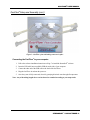
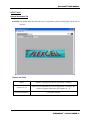
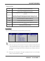
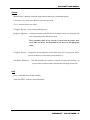
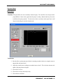
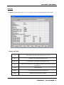
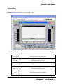
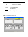
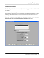
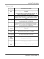
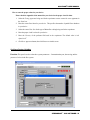
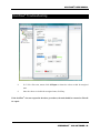
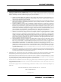
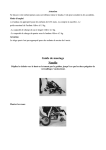
Osci-Flow Flow Controller Users Manual FLEXCELL INTERNATIONAL CORPORATION 2730 TUCKER STREET, SUITE 200 BURLINGTON, NC 27215 USA 800-728-3714 (USA ONLY) OR 919-732-1591 WWW.FLEXCELLINT.COM DECEMBER 2014 Copyright © 2004 Flexcell International Corporation ® OSCIFLOW® USER MANUAL Table of Contents TABLE OF CONTENTS............................................................................................................................................................. 2 GETTING STARTED ................................................................................................................................................................. 3 INTRODUCTION ........................................................................................................................................................................... 4 OSCIFLOW® SYSTEM SPECIFICATIONS: ..................................................................................................................................... 4 OSCIFLOW® COMPONENTS ........................................................................................................................................................ 4 OSCIFLOW® SETUP AND ASSEMBLY.......................................................................................................................................... 4 STREAMSOFT V4.2 SOFTWARE ....................................................................................................................................... 7 INSTALLATION INSTRUCTIONS ................................................................................................................................................... 7 MAIN PANEL ............................................................................................................................................................................... 8 General Information Tab ...................................................................................................................................................... 8 System Tab............................................................................................................................................................................ 9 Pre-Test Configuration ....................................................................................................................................................... 10 Pull-down Menus................................................................................................................................................................ 11 OPERATE MENU........................................................................................................................................................................ 13 Manual Mode ...................................................................................................................................................................... 13 View Data............................................................................................................................................................................ 14 Configure Users .................................................................................................................................................................. 15 Configure Regimes: Setup Parameters .............................................................................................................................. 16 Configure Testing Apparatus ............................................................................................................................................. 19 Configure System Variables............................................................................................................................................... 21 Reinitialize Hardware ......................................................................................................................................................... 22 STREAMSOFT V4.2 NOTES ....................................................................................................................................................... 23 DOING AN EXPERIMENT ..................................................................................................................................................... 24 CREATING A REGIME ................................................................................................................................................................ 24 FILLING THE SYSTEM TO ELIMINATE AIR BUBBLES ............................................................................................................... 25 OSCIFLOW® TROUBLESHOOTING .................................................................................................................................. 26 WHEN THE OSCIFLOW® VALVES ARE NOT RESPONDING......................................................................................................... 26 WARRANTY INFORMATION .............................................................................................................................................. 29 CONTACTING FLEXCELL ................................................................................................................................................... 31 STREAMSOFT V4.2 SOFTWARE 2 OSCIFLOW® USER MANUAL Getting Started Introduction Fluid-induced shear stress occurs in every tissue in the body as a result of interstitial fluid movement. Tissue deformation by compression, tension or shear forces results in the movement of interstitial fluid around cells. Fluid movement acts as a transport vehicle for ions, proteins, carbohydrates and other molecules capable of movement within the matrix. As the fluid moves past cell membranes, a shear stress, , is generated. If one assumes that laminar flow occurs through a parallel-plate flow chamber, fluid-induced shear stress values can be determined with the following formula: = 6Q/bh2, where is the shear stress in dyne/cm2, is the viscosity of the fluid in dyne.s/cm2, Q is the flow rate in ml/s, b is the width of the flow channel in cm, and h is the height of the flow channel in cm. Shear stress in the vascular system may vary from less than 1, to more than 35 dyne/cm2. Fluid shear stress in canaliculi of bone may vary from 1 to 20 dyne/cm2, while in cartilage it may be in the range of 1 to 5 dyne/cm2. The OsciFlow® is a software-controlled valve-operated device designed to provide oscillatory or start-stop flow patterns to cells cultured in the Streamer, FlexFlow or other perfusion devices. Both the Streamer and FlexFlow are parallel-plate flow systems designed to apply fluid-induced shear stress to cells grown in a monolayer. The OsciFlow® regulates flow direction by choreographing the closing and opening a collection of pinch valves. This carefully timed action serves to constrict or release tubing thus directing the fluid flow through the desired channels. The OsciFlow® device is able to regulate flow both in an oscillatory (flow reversal) manner and in a pulsatile (square wave) mode, where the flow is stopped and then restarted after a designated period of time. Software control through StreamSoft software allows the user to regulate frequency of oscillation or pulsatile patterns, as well as shear stress levels applied to cells. Individual protocols can be designed for flow experiments. The frequency of oscillation or pulsation is specified by programming seconds ON and seconds OFF in the software. An advantage that the OsciFlow® has over other flow reversal techniques is that it overcomes inertial lag. Other techniques for flow reversal rely on a change of pump – motor rotation. With this strategy, the inherent inertial effects associated with the deceleration and acceleration creates an unavoidable response lag time. As the OsciFlow® does not require a pump – motor to change directions, near instantaneous flow reversal can be achieved with less wear and tear on pumps and motors. STREAMSOFT V4.2 SOFTWARE 3 OSCIFLOW® USER MANUAL OsciFlow® System Specifications: Maximum Frequency of Oscillation: 1Hz (0.5 sec on/ 0.5 sec off) Minimum Frequency of Oscillation: No limit Maximum Frequency of Pulsation: 1Hz (0.5 sec on/ 0.5 sec off) Minimum Frequency of Pulsation: No limit Maximum Flow Rate through valves: No Limit Pinch Valve Maximum Pressure: 20 psi Pinch Valve Maximum Fluid Temperature: 158F (70°C) Box Dimensions: 13” x 7.5” x 7.5” (33cm x 19.1cm x 19.1cm) Box Weight: 14lbs (6.4kg) Power Requirements: 120V, 0.15A Tubing sizes accepted: MasterFlex L/S 16, L/S 25, L/S 17 Interface Connection to computer: USB OsciFlow® Components OsciFlow® Device USB cable OsciFlow® Tubing (includes quick disconnect fittings) Additional tubing lengths necessary for connecting to flow system StreamSoft software V4.2 Dell Inspiron notebook computer (optional) OsciFlow® Setup and Assembly The following instructions are for integrating the OsciFlow® into the Streamer and/or FlexFlow systems. When using the OsciFlow® with either system, the box should not be placed in the incubator with the flow device and its other components. The OsciFlow® should be placed on top or beside the incubator, as near as possible to the port through which the tubing enters the incubator. This will minimize the amount of fluid that is exposed to atmospheric temperatures. STREAMSOFT V4.2 SOFTWARE 4 OSCIFLOW® USER MANUAL OsciFlow® Setup and Assembly (cont.) The OsciFlow® is very easily integrated into the Streamer and FlexFlow systems. A special tubing connector is provided with the OsciFlow® that will connect directly in line with the Streamer or FlexFlow system, with the addition of two more tubing lengths provided with the OsciFlow®. 1. Connect the OsciFlow® tubing connector to the front of the OsciFlow® as shown below. Push the tubing all the way into the pinch valves so that each piece is fully inserted and pinched between the valve body and pinching mechanism. The connector must be inserted as shown below, such that the each of the four pieces of tubing is connected to their respective valve. 2. Find a location for your OsciFlow® that is as near as possible to the port hole on the back or top of your incubator. Place the OsciFlow® such that the tubing connector quick disconnects are in close proximity to the port hole. 3. Disconnect the male quick disconnect that is currently connected to the inlet of your Streamer or FlexFlow device and connect it to the bottom left female quick disconnect (refer to Figure 1) of the OsciFlow® tubing connector. 4. Disconnect the male quick disconnect that is currently connected to the outlet of your Streamer or FlexFlow device and connect it to the top left female quick disconnect (refer to Figure 1) of the OsciFlow® tubing connector. 5. Use one of the tubing lengths provided with the OsciFlow® to connect the top right female quick disconnect (refer to Figure 1) on the OsciFlow® tubing connector to the inlet of your Streamer or FlexFlow device. 6. Use the other tubing length provided with the OsciFlow® to connect the bottom right female quick disconnect (refer to Figure 1) on the OsciFlow® tubing connector to the outlet of your Streamer or FlexFlow device. STREAMSOFT V4.2 SOFTWARE 5 OSCIFLOW® USER MANUAL OsciFlow® Setup and Assembly (cont.) Figure 1: OsciFlow® front with tubing connector in place Connecting the OsciFlow® to your computer: 1. Follow the software installation instructions on Page 7 to install the StreamSoft™ software. 2. Insert the USB cable into an available USB slot on the side of your computer. 3. Connect the other end of the USB cable to the back of the OsciFlow®. 4. Plug the OsciFlow® in and turn the power on. 5. Once the system is fully connected, clean it by pumping deionized water through all components. Note: Any of the tubing lengths above can be shorted or extended according to your setup needs. STREAMSOFT V4.2 SOFTWARE 6 OSCIFLOW® USER MANUAL StreamSoft ™ V4.2 Software Installation Instructions 1. Insert the StreamSoft™ V4.2 DVD into the DVD-ROM drive on the computer 2. Double click My Computer (Windows XP) or Computer (Windows Vista/Windows 7) 3. Double click the DVD-ROM drive 4. Double click the Setup installer The installer will now open and run 5. On the Product Notification screen click Next 6. On the Destination Directory screen click Next 7. On the License Agreement screen click I accept the License Agreement and then click Next 8. On the next License Agreement screen click I accept the above 2 License Agreement(s) and then click Next 9. On the Start Installation screen click Next Installation of the required National Instruments and StreamSoft™ software will now begin 10. Once the installation is complete click Finish and restart the computer 11. Turn on the OsciFlow® and connect the USB cable to the back of it 12. Insert the opposite end of the USB cable into an open USB slot on the computer. The computer should make a sound, recognizing that the OsciFlow® has been found, and the correct drivers will install 13. Installation of StreamSoft™ V4.2 is now complete Note: When the Select Pump to Use window appears when opening the StreamSoft™ V4.2 software, select the pump named MasterFlex Peristaltic Pump to ensure correct function of the equipment Setting up parameters in StreamSoft™ V4.2 Specific parameters will need to be set up in StreamSoft™ V4.2 to customize it for your particular device and system. Setting up these parameters is extremely important to ensure accurate flow results for your system. For instructions on setting up these parameters, see Configure Testing Apparatus and Configure System Variables, Pages 19 to 22. Complete this setup before proceeding with any experiments. STREAMSOFT V4.2 SOFTWARE 7 OSCIFLOW® USER MANUAL Main Panel General Information Tab Function: The default main panel allows the user to verify that the system is running and to stop the tests at any time. Buttons and Fields Status Number is bright green when an experiment is running System 1,2,3,4 These tabs will automatically become highlighted according to the number of pumps connected to the computer (1 - 4). General Information Current date and time STREAMSOFT V4.2 SOFTWARE 8 OSCIFLOW® USER MANUAL System Tab Function: This panel is used to run the experiments. Each System tab is identical. Buttons and Fields User Current user in currently configured regime Regime Regime currently configured Apparatus Device being used with the software (Streamer™ or FlexFlow™) Data File Name of file to which data is being saved (if appropriate) Configure Configure (load) the experiment. The Pre-Test Configuration window will appear. Start Start the experiment. Stop Pause Terminate the experiment. This button is only active when an experiment is running. Suspend the experiment. The pump will stop, but the test regimen is kept in memory. STREAMSOFT V4.2 SOFTWARE 9 OSCIFLOW® USER MANUAL Resume Resume a paused experiment. Graph This graph shows the expected and actual shear stresses during the experiment. Elapsed Time (h:m:s) Elapsed time in the current experiment Loop Current loop in the current step or series of steps Pulse # Total number of pulsations (square wave) or oscillations (FWD/REV) produced by the valves in this regime Step Current (active) step in regime Direction Current flow direction (FWD/REV) Pre-Test Configuration Function: This panel allows the user to configure the parameters of an experiment. It appears when the user presses the Configure button on the System panel. The information selected here is transferred to the User, Regime and Apparatus fields on the System panel. STREAMSOFT V4.2 SOFTWARE 10 OSCIFLOW® USER MANUAL Buttons and Fields Users List of all users. Select users with the mouse. Regimes List of regimes created by the previously selected user. Select from list by using the mouse to highlight the desired regime. List of configured flow devices. Select the device that will be used for the experiment Apparatus Important: Be sure that all parameters have been properly set for your device in the Configure Testing Apparatus window. See Pages 19 to 21. Print Print the current panel to a printer or HTML file. Update Use the current selections to run the experiment. Cancel Cancel any new selections and use the previously configured setup for the experiment. Help Online help (not currently available) Pull-down Menus This section summarizes the function of each item in the three pull-down menus. File -Print -Exit Operate -Manual Mode -View Data -Users -Configure Regime -Configure Apparatus -Configure System -Reinitialize Hardware Help -Help -About LabVIEW File Print – Allows user to print a copy of the current panel. This system is configured such that printing sends a copy of the panel being viewed to a printer or to an html file. If there is no printer connected to the computer, an error message from the Windows default printer queue will appear when the user tries to print. Exit – Allows user to close the program. If the pump is operating at the time of exit, it will continue running. The keyboard short-cut is Ctrl-Q. STREAMSOFT V4.2 SOFTWARE 11 OSCIFLOW® USER MANUAL Operate Manual Mode – Manually control the pump without setting up an experimental regimen. View Data – View shear stress data from a previous experiment. Users – Add and remove user names. Configure Regime – Create an experimental protocol. Configure Apparatus – Configure parameters of the flow device so that the software can assign the flow rates corresponding to the desired shear stress. These parameters must be set correctly to ensure that the proper shear stress values are shown. See the manual of your device for the appropriate values. Configure System – Configure the system parameters such as data saving, the Com port used and the presence or absence of valves in the system (OsciFlow®). Reinitialize Hardware – This will reinitialize the software to connect the pump and OsciFlow® (if present) in the event that a cable is disconnected or the pump is turned off. Help Help – Online help (not currently available) About LabVIEW – Software version information STREAMSOFT V4.2 SOFTWARE 12 OSCIFLOW® USER MANUAL Operate Menu Manual Mode Function: This panel allows the user to manually control the pump. The actual flow rate and speed of the pump (RPM) are shown on the graph when the pump is working. Manual mode may be used to troubleshoot the pump operation. The shear stress value is not shown on this panel since it will depend on the tubing size and flow chamber used. Instructions 1. Enter the flow set point (pump speed) either by entering a number in the box or using the mouse to drag the dial to the desired level. 2. Adjust the seconds between readings to a number between 0 and 5. This is the time between each update of the pump data on the graph. 3. Click on Press to Start. 4. Click on Press to Stop when ready to stop. 5. Click on Return when done. STREAMSOFT V4.2 SOFTWARE 13 OSCIFLOW® USER MANUAL View Data Function: This panel allows the user to view previously collected experimental data in a table format. Buttons and Fields File The complete file path to the data file being viewed Table Contents of the experimental data log file Export File Export data to a spreadsheet-compatible format Print Print a copy of this panel to the Windows default printer or write a copy to an HTML file. Open Open a data file. Return Close this panel and return to the Main panel. Help Online help (not currently available) STREAMSOFT V4.2 SOFTWARE 14 OSCIFLOW® USER MANUAL Configure Users Function: This panel allows the user to create or delete users. Buttons and Fields Existing Users Lists all current users of the system User Name Field used to enter new users Add User Add new users to the system. Delete User Delete users from the system. Help Online help (not currently available) STREAMSOFT V4.2 SOFTWARE 15 OSCIFLOW® USER MANUAL Return Exit this panel and return to the Main panel. Instructions To add a user: 1) Type the name into the User Name field. 2) Press the Add User button. To delete a user: 1) Using the mouse, select the user from the list of Existing Users. 2) Press the Delete User button. If the user has any stored regimes and data sets, the operator will be prompted to confirm the deletion. Configure Regimes: Setup Parameters Function: This panel allows the user to configure (create) a regime. STREAMSOFT V4.2 SOFTWARE 16 OSCIFLOW® USER MANUAL Buttons and Fields Existing Users List of all users; select a user from the list using the mouse. Regimes for Selected Users List of regimens created by the current user. Selecting from this list will load that regimen and allow the user to view and/or modify that regime. Regime Name Name of the current regimen; if creating a new regimen, enter a name in this field. Time Between Time elapsed between computer updates of the pump parameters; default is 1 second. Pump Updates Time Between Data Log to File Time interval between each computer sampling of the experimental flow data. Default value is 10 seconds. For an extremely long test, increase this interval to reduce the size of the data file. Note: this function only applies when the data saving option is selected in the Configure System Variables window. See Pages 21 and 22. Estimated file size This is an estimate of how large the data file would be given the total test length and the time between data. Note: this function only applies when the data saving option is selected in the Configure System Variables window. See Pages 21 to 22. Step Current step number selected or being modified Step Name Name of the currently selected step Flow Type Specifies the direction or type of flow for this step (forward, reverse, pulsed (square wave), oscillation) ON/HI (s) When using pulsed (square wave) or oscillatory flow, specifies how long the valves remain in a position to allow the fluid flow to continue unhindered or flow in the forward direction, respectively. For normal forward or reverse (unidirectional) flow, this value remains at 1.00. OFF/LO (s) When using pulsed (square wave) or oscillatory flow, specifies how long the valves remain in a position to stop the fluid flow to the device or cause it to flow in the reverse direction, respectively. For normal forward or reverse (unidirectional) flow, this value remains at 1.00. Shear (dyne/cm^2) The value of shear stress to be applied to the cells in this step. Duration (h:m:s.ss) Time to spend in this step (hours:minutes:seconds.milliseconds) STREAMSOFT V4.2 SOFTWARE 17 OSCIFLOW® USER MANUAL GoTo To create a loop, indicate which step to go back to. The GoTo step must always be a step number before the current step. Loop Indicates how many times to loop between the GoTo step and the current step. Summary Table This table is a listing of the current steps in the regimen. Selecting a row from this table will allow the parameters of the step to be viewed and modified. Insert Step Insert a step into the regimen before or after the current step. Delete Step Delete the currently selected step. New Regime Clear all parameters and start a new regime. Type in a new name under Regime Name and select Insert Step. Delete Regime Delete the currently selected regime. Save Regime Save a new or modified regime. Return Exit this panel and return to the Main Panel Check Shear Check the shear stresses entered in your regime to see if they are achievable with the apparatus, pump and tubing size that you are using. Print Print the current panel to a printer or an HTML file. Help Online help (not currently available) Instructions on how to set all the parameters for an experiment are included in the Doing an Experiment section of this manual. STREAMSOFT V4.2 SOFTWARE 18 OSCIFLOW® USER MANUAL Configure Testing Apparatus Function: This panel allows the user to create, modify or delete a testing apparatus (Streamer or FlexFlow flow chamber). As each Streamer and FlexFlow device is manufactured to strict dimensional specifications, the values for the height and width of the chambers must be entered into the software for each individual device. These values are measured for your specific device and must be correct for accurate shear stress measurement. The values can be found in the appendix of the manual for your device. STREAMSOFT V4.2 SOFTWARE 19 OSCIFLOW® USER MANUAL Buttons and Fields Testing Apparatus List of all flow devices available Name When a testing apparatus is selected, this field (and the parameters) will be updated. Flow Factor Hose Size b A factor that accounts for any parallel paths in the flow stream. This number is 6 for the Streamer and 1 for the FlexFlow. Hose size determines how fast the pump must move to achieve the desired flow rate and shear stress level. The sizes listed are standard for Masterflex tubing. Select the hose size that you are using with your system. Width of the flow area (cm) in a single chamber of the Streamer or FlexFlow device. This number is found in the back of the manual for your device listed as Flow Area Width (cm). h Height of the flow area (cm) in a single chamber of the Streamer or FlexFlow device. This number is found in the back of the manual for your device listed as Flow Area Height (cm). Viscosity Viscosity of the perfusate/media used in the experiment. The standard value is 0.01. Print Print the current panel to a printer or an HTML file. Save Apparatus Save changes to the apparatus listed in Name. Delete Apparatus Deletes apparatus listed in Name. Help Online help (not yet available) Return Exit this panel and return to the Main panel. Any changes that have not been saved will be discarded. STREAMSOFT V4.2 SOFTWARE 20 OSCIFLOW® USER MANUAL How to enter the proper values for your device: Please check the Appendix of the manual for your device for the proper b and h values. 1. Select the Testing Apparatus being used for the experiment or enter a name for a new apparatus in the Name box. 2. Enter the correct flow factor for your device. This specifies the number of parallel flow chambers in your device. 3. Select the correct Hose Size for the type of Masterflex tubing being used in the experiment. 4. Enter the proper b and h values for your device. 5. Enter the Viscosity of the perfusate fluid used in the experiment. The default value is 0.01 dynes*s/cm2. 6. Click Save Apparatus button, then click Return to exit this screen. Configure System Variables Function: This panel is used to select three system parameters – Communications port, data saving, and the presence of valves in the flow system. STREAMSOFT V4.2 SOFTWARE 21 OSCIFLOW® USER MANUAL Buttons and Fields Pump Serial Port Com 1 is the default port. This should be changed only if there is a conflict with this port on your computer. Save Data? Select this option if you want to save regime data files. Valves in System? Select this option if you are using the OsciFlow® Flow Controller. Reinitialize Hardware Function: This panel will appear when the computer program is first started. It will also appear when the Reinitialize Hardware item is selected in the Operate menu. When the system is properly initiated, the pump will display PO1 and the OsciFlow® valves will click. If power to the pump is cycled during experimentation, or communication is lost, the user should reinitialize the hardware before turning off the program and starting it again. STREAMSOFT V4.2 SOFTWARE 22 OSCIFLOW® USER MANUAL StreamSoft™ V4.2 Notes When running a regime in StreamSoft™ V4.2, do not run other applications on the same computer. The communication timing to the pump and OsciFlow® requires full CPU availability. If another program or operation is running that requires CPU power, it is possible that the pump or valve timing could be interrupted. This effect may be noticeable when using the OsciFlow® at a higher frequency than 2 seconds on, 2 seconds off, or when oscillating the pump speed to create pulsatile flow. When the Select Pump to Use window appears when opening the StreamSoft™ V4.2 software, select the pump named MasterFlex Peristaltic Pump to ensure correct function of the equipment STREAMSOFT V4.2 SOFTWARE 23 OSCIFLOW® USER MANUAL Doing an experiment Creating a Regime 1. From the main panel, select the Configure Regimes item in the Operate menu. 2. Click on an existing user name. 3. To create a new regimen, click on New Regime. Enter a name in the Regime Name field. 4. Click Insert Step; give this step a name in the Step Name field. 5. Click on Save Regime. The regime name should appear in the Regimes for Selected Users field at the top. 6. Specify the Flow Type (FWD, REV, PULSED, OSCILLATION), ON/HI & OFF/LO times (only when using the pulsed or oscillation functions; see Page 17 for more details), Shear, and Duration for this step. Click on Save Regime to save all information entered up to this point. Note: If you are using the OSCILLATION function, create a first step in the regime in FWD mode. This step is required to push out the air that remains in the top of the Streamer after the top is opened for slide insertion. The first step will push this air through to the outlet in the medium bottle. If you wish to add additional steps: 7. Click Insert Step. You will be queried as to whether this step should be inserted before or after the current step. Click on before or after according to your preference. Enter the preferred parameters as in #6. If this step was inserted after the step entered in #6, you can also use the GoTo and Loop options to loop through steps 1 and 2. Under GoTo in step 2, enter “1”. Under Loop, enter the number of times that you would like to loop through steps 1 and 2. 8. Add additional steps as desired. Once the regime is complete, click on Save Regime. 9. Optional: Check the shear stress(es) in your regime to be sure that they are achievable with your apparatus, tubing size and pump. Click on Check Shear at the bottom of the Configure Regimes window while your regime is selected (see Pages 13 to 16). The Pre-Test Configuration window will appear (see Page 10). Select a user, regime, and apparatus. Click on Update. The software will tell you if your shear stresses are achievable with this apparatus and the tubing size and pump assigned to it. Modify shear stresses if necessary. 10. The regime is now ready to run. STREAMSOFT V4.2 SOFTWARE 24 OSCIFLOW® USER MANUAL Filling the System to Eliminate Air Bubbles Before using the OsciFlow® system with cells, all of the tubing must be filled with media and all air bubbles removed. To fill the system, create a regime with two steps, the first in FWD mode and the second in REV mode. Each step should be 2 minutes at a shear stress level ½ that of which your device is capable. This will give sufficient time for fluid to fill all of the tubing. As you notice air bubbles in the silicone tubing at different locations, shake the tubing to release the air bubbles. STREAMSOFT V4.2 SOFTWARE 25 OSCIFLOW® USER MANUAL OsciFlow ® Troubleshooting When the OsciFlow® valves are not responding When the OsciFlow® valves do not respond, the following troubleshooting steps should be taken: Check that the OsciFlow® is powered on. The red light on the front of the box should be illuminated. Check all connections to be sure that they are intact: one end of the USB cable should be fully inserted into the USB slot on the side of the computer, and the end should be connected to the back of the OsciFlow®. Check that tubing has been inserted into the OsciFlow® pinch valves. If there is no tubing in the valves, they will not return to their "off" position and the device will appear to be malfunctioning. Stop and restart the software. The OsciFlow® valves should click as the software is initializing. If the valves do not click, open the Operate menu in the software and select the Configure System option. Make sure that the Valves in System? option is selected. If not, select this option and click Return. If the valves do not click at this point, proceed with the following steps: 1. Close the StreamSoft™ software so that nothing is running but the Windows® environment. 2. Disconnect the USB cable from the computer. 3. Turn off the OsciFlow®. 4. Turn on the OsciFlow® and reconnect the USB cable to the computer. 5. Start the StreamSoft™ software. The OsciFlow® valves should click as the computer is initializing the hardware. If the valves do not click, proceed with the following steps: 1. With the OsciFlow® powered on and with all connections intact, open up the Measurement & Automation explorer from the Desktop of your computer. If there is not a shortcut on the Desktop, check in the folder named National Instruments in All Programs under the Start menu. STREAMSOFT V4.2 SOFTWARE 26 OSCIFLOW® USER MANUAL OsciFlow ® Troubleshooting 2. Under Devices and Interfaces click on NI-DAXmx Devices. NI USB-6501: “Dev1” should be listed. 3. Right click on this device and choose Test Panels. 4. A warning window will might appear. Simply click Yes to continue. 5. If a second warning window appears before the Test Panels appear, this means that the computer is not recognizing the OsciFlow®. In this case, contact Flexcell. 6. Once the Test Panels appear, in the Digital I/O tab the following information will be shown 7. In 2. Select Direction, mouse click Output (0) numbers 7, 6, 5 and 4, then click Start. At this point, two of the valves should click. STREAMSOFT V4.2 SOFTWARE 27 OSCIFLOW® USER MANUAL OsciFlow ® Troubleshooting 8. In 2. Select Direction, mouse click All Input to release the valves to their de-energized state. 9. Once the valves are in their de-energized state, click Stop. If the OsciFlow® does not respond in the above procedures, the unit should be returned to Flexcell for repair. STREAMSOFT V4.2 SOFTWARE 28 OSCIFLOW® USER MANUAL Warranty Information 1. FLEXCELL INTERNATIONAL CORPORATION warrants to the original purchaser/customer all hardware components of the OsciFlow® System for a period of one year from the date of delivery to the purchaser/customer to be free from manufacturing defects in workmanship or materials with the following exceptions, terms and conditions: a. b. c. d. e. f. g. 2. ITEMS EXCLUDED FROM THE WARRANTY ARE: software, disks, manuals and external peripherals such as printers, mouse or track ball units, imaging devices, vacuum pumps, air tanks, electric voltage converters, compressors, surge suppressers and all other accessory equipment. DURING THE WARRANTY PERIOD, the purchaser/customer must notify Flexcell of any warranty claim in writing, by telephone, fax transmission or email identifying each defective part or specifically describe the exact problem no later than the last day the warranty is in effect. FLEXCELL AGREES to correct any defect in workmanship or material and supply new or rebuilt parts in exchange for defective parts upon completion and submission by purchaser/customer of a printed “Parts Return Authorization” form furnished by Flexcell. Parts must be properly packed in original container and shipped to our factory service center or distributor with all shipping costs prepaid if the unit is out of warranty coverage. If the original shipping box is not available, Flexcell will send the required protective shipping container. (Flexcell will recommend the insurance value for parts or equipment to be shipped.) Return carrier shipping costs will be paid by Flexcell from the service center. The purchaser/customer is solely responsible for payment of custom fees, taxes, holding fees or value added taxes. THIS LIMITED WARRANTY only covers failures due to defects in materials or workmanship which occur during normal use. It does not cover damage which occurs in shipment or failures of original equipment due to products identified as add-ons not manufactured by Flexcell International Corporation or its distributors nor does this limited warranty cover damages or failures which result from accident or disaster such as fire, explosion, flood, wind, lightning, or earthquake or misuse, abuse, neglect, mishandling, misapplication, alteration, faulty installation, modification or service by anyone other than our factory or distributor. This warranty is extended only to the original purchaser/customer unless a transfer of ownership is approved by Flexcell in writing. LIMITED LIABILITY. Flexcell or its distributor’s only liability shall be to remedy any defect to comply with its warranty and return the repaired equipment to function as designed. Under no circumstances shall Flexcell or its distributors be liable for any special incidental or consequential damages based upon breach of warranty or contract or negligence. Such damages include, but are not limited to: loss of profits, revenue, loss of data, down time, customer’s material or time. DISCLAIMER OF WARRANTIES: The Limited Warranty expressed in the foregoing language is the only warranty applicable to this product. Any other warranty, expressed or implied warranty or of merchantability or fitness for a particular purpose are hereby disclaimed. No oral or written information or advice provided by Flexcell, through its agents or employees, in the use and functioning of the equipment shall in any way create a warranty or in anyway increase the scope of this limited warranty. DISCLAIMER: LANGUAGE. This warranty document, accompanying instruction manual and supplemental applicable laws appear in the English language. In the event of any inconsistency in the meaning of the words and terminology and any foreign language translation, the English language shall prevail. GOVERNING LAW. The performance of the duties and liabilities of the parties under the terms and conditions of this Limited Warranty shall be governed in all respects by the laws of the Commonwealth of Pennsylvania, the United States of America. APPLICATION OF STATE LAWS: Some states do not allow the exclusion or limitation of consequential damages nor do some states allow limitations on how long an implied warranty lasts, so the above limitations may not apply to you. This warranty gives you specific legal rights and you may also have other rights which vary from state to state. 3. INTERNATIONAL CUSTOMERS. The full text of the foregoing limited warranty and all disclaimers is applicable to international customers/purchasers except when the purchase was made from an international distributor or reseller, the warranty will be covered through your distributor or reseller. If technical advisory support service is not available through your distributor or reseller, for service contact warranty headquarters by phone or fax. Within the United States only - Toll Free 1-800-728-3714 - Fax: 1-919-732-5196 Email : [email protected] Issued April 2011 STREAMSOFT V4.2 SOFTWARE 29 OSCIFLOW® USER MANUAL NOTICE The information in this document is subject to change without notice. Flexcell International Corporation assumes no responsibility for any errors that may appear in this guide. This manual is believed to be complete and accurate at the time of publication. In no event shall Flexcell International Corporation be liable for incidental or consequential damages in connection with or arising from the use of this manual. STREAMSOFT V4.2 SOFTWARE 30 OSCIFLOW® USER MANUAL Contacting Flexcell North America Flexcell International Corporation 2730 Tucker Street Suite 200 Burlington NC 27215 USA Phone: 919-732-1591 800-728-3714 (USA only) Fax: 919-732-5196 Email: [email protected] Web: www.flexcellint.com Taiwan Nature Opera Biotechnology, Inc. 9F-2, No.70 Sec.4, Cheng Kung Rd. Nei-Hu Dist. Taipei Taiwan Phone: +886-2-27905097 Fax: +886-2-27931322 Email: [email protected] Europe Dunn Labortechnik GmbH Thelenberg 6 56567 Asbach Germany Brazil Sellex, Inc. 5225 Wisconsin Ave, NW Suite 306 Washington, DC 20015 Phone: Fax: Email: Web: Phone: 5506-4646 Fax: 5505-7433 Web: www.sellex.com +49-2683-43094 +49-2683-42776 [email protected] www.dunnlab.de Japan LMS CO. LTD. 3-6-7, Hongo, Bunkyo-ku, Tokyo 113-0033 Japan China, Hong Kong, Malaysia Bio Excellence International Tech Co., Ltd Email: [email protected] Web: www.bio-goods.com Phone: +81-3-5842-4171 Fax: +81-3-5842-4180 Email: [email protected] STREAMSOFT V4.2 SOFTWARE 31