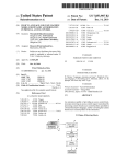
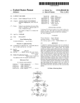
1
US007490314B2
(12) Unlted States Patent
(10) Patent N0.2
Yuknewicz et al.
(54)
(45) Date of Patent:
SYSTEM AND METHOD FOR EXPOSING
(56)
I
' P
lY kn
R dm
U'S' PATENT DOCUMENTS
d WA Us '
4,674,065 A
6/1987 Lange et a1. .............. .. 364/900
mentors‘ wiuh “l HeWllclZ’K _ek1 0; WA (S )’
s_lc aeC larst ’1 Ir 2“; ’WA gs
5,267,155 A
5,392,386 A
11/1993 Buchanan et a1. .... .. 364/419.14
2/1995 Chalas ..................... .. 395/155
“non
_
a Ver ’ Ssaqu? ’.
(
)’
Donna
Wallace, Wood1nv1lle, WA (US);
_
Antolne Cote,
Redmond,
WA (US);
,
.
Fred Balslger, Carnatlon, WA (US);
.
.
.
.
Nlkhll Kothan’ Sammamlsh’ WA (Us);
5,557,730 A *
9/1996 Frid-Nielsen ............. .. 715/839
5,736,974 A *
4/1998
Selker ...................... .. 715/862
5,815,830 A
9/1998
Anthony
5,859,636
1/1999
Pandlt
A
5 946 647 A
Brian Pepin, Seattle, WA (US); Jeffrey
’
.
..... ..
8/1999 Miller et al
’
704/9
(Continued)
Krishna Mohan, Redmond, WA (US);
Andrew Cheng-min Lin, Seattle, WA
OTHER PUBLICATIONS
(Us); Joseph F- Kubiniec, Seattle, WA
Abiteboul, S. et al., “A Logical View of Structured Files”, The VLDB
(US); James Schmelzer, Seattle, WA
(US); Corrina Barber, Snohomish, WA
(US); Anson M. Horton, Sammamish,
WA (US); Meghan Rae Perez,
Redmond; WA (U S)
Journal, 1998, 7, 96-114.
C t, d
( on mue )
Primary ExamineriWeiY. Zhen
Assistant ExamineriMattheW J Brophy
_
(74) Attorney, A gent, 0r FirmiWoodcock Washburn LLP
(73) Ass1gnee: Microsoft Corporation, Redmond, WA
(US)
Notice:
345/335
' """"""""" "
Chrisope, Kirkland, WA (US); Graeme
Mott, Redmond, WA (US); Christopher
Dias, Kirkland, WA (US); Bulusu
(*)
Feb. 10, 2009
References Cited
TASKS IN A DEVELOPMENT
ENVIRONMENT
(75)
US 7,490,314 B2
(57)
ABSTRACT
Subject to any disclaimer, the term of this
patent is extended or adjusted under 35
U80 1546)) by 833 days'
_
f
_
_d d h
_
h d
1
Ausermter ace 1s prov1 e t at exposes 1tems suc as eve -
oper tasks, commands, property settmgs, and other related
(21)
Appl. NO-I 10/768,522
information to a user. The user interface may be invoked in a
(22)
Filed
number of development interfaces such as, for example, a
'
(65)
Jan 30 2004
l
’
designer or an editor. The user interface may be either an
PI‘iOI‘ PllblieatiOIl Data
object bound interface or an action triggered interface. An
object bound interface exposes a set of items that are associ
US Zoos/0171967 A1
(51)
Aug' 4’ 2005
ated With a corresponding object. An action triggered inter
Int. Cl.
G06F 9/44
face exposes a set of items that are associated With a corre
(2006.01)
sponding triggering action. In addition to enumerating
(52)
us. Cl. ..................................... .. 717/105; 715/810
developertasks, the user interface may provideadirect link to
(58)
Fleld
0f Classi?cation
Search ....... .. 717/100 i 113,
oth er mter
'
facesth at
717/120; 715/810
See application ?le for complete search history.
tas k executlon.
'
31 Claims, 13 Drawing Sheets
Designer 210a
Form 320
(
Control 32
fac1'1'1tate
EE
310a
Panel 410a
Auto Fonnat
Edit Columns
Add Column
IZEnable Adding
ElEnable Editing
ElEnable Deleting
US 7,490,314 B2
Page 2
Source Insight Program Editor and Analyzer, http://www.sourcedyn.
US. PATENT DOCUMENTS
com/index.html, 2 pages.
6,085,201 A
7/2000
6,122,647 A
9/2000 Horowitz et a1. ..
707/513
1/2001
717/100
6,182,279 B1*
Tso .......................... .. 707/505
Buxton .............. ..
6,305,008 B1
10/2001 Vaidyanathan et al.
6,311,323 B1
10/2001
Shulman et al. ........... .. 717/111
6,367,068 B1
4/2002 Vaidyanathan et al.
6,405,364 B1*
6/2002
6,502,233
7,017,143
7,055,136
7,139,999
717/4
..
Borland, CodeWright The Programmer’s Editing System, http://
www.premia.com, 1 page.
Chalmers-Physical Resource Theory, “The Complex Adaptive Sys
tems Programmer of year 2000”, http://www.frt.fy.chalmers.se/
kristian/software.html, 1 page.
Emacs/W3 v 4.0, http://www.cs.indiana.edu/elisp/w3/docs.html, 1
Bowman-Amuah ....... ..
page.
B1
B1*
12/2002 Vaidyanathan et al. .... .. 717/101
3/2006 Andrew et al. ............ .. 717/100
Vi: A Unix text editor, http://www.indiana.edu/~ucspubs/b104/ztoc.
html, 8 pages.
B2 *
B2 *
5/2006
11/2006
Dzoba et a1. ....... ..
Bowman-Amuah ..
MacroMedia, Inc., Director MX, Using Director, Copyright © 2004,
7,299,419 B2 *
11/2007
Evans ................ ..
2004/0221262 A1*
717/125
.
11/2004 Hampapuram et al. .... .. 717/113
OTHER PUBLICATIONS
Anderson, K.M. et al., “Chimera: Hypertext for Heterogeneous Soft
ware Environments”, ECHT Proceedings, Sep. 1994, 94-107.
Breidenbach, G., “Programmable Keyboard Controller”, Electronic
Praxis, 2001, 6, 68-70 (English Language Abstract).
Hayes, P.J. et al., “A Logical View of Types”, Association for Com
puting Machinery, 1980, 128-130.
Henninger, S. et al., “A Tool For Managing Software Development
Knowledge”, PROFES, 2001, LNCS 2188, 182-195.
Holmes, N., “Seven Great Blunders of the Computing World”, Com
puter, 2002, 110-112.
Hughes, G. et al., “Microsoft Smart Tags: Support, ignore or con
demn them?”, HT, 2002, 80-81.
Jewell, D. “Windows Shell Secrets”, EXE, 1999, 13(9), 35-45.
Kramer, B. “3D LISP Tools”, Cadence, 1989, 4(5), 130-134.
Kucza, T. et al., “Improving Knowledge Management in Software
Reuse Process”, PROFES, 2001, LNCS 2188, 141-152.
Lewis, P.H. et al., “Media-based Navigation with Generic Links”,
Hypertext, 1996, 215-223.
Lin, C.F. et al., “Chinese Text Distinction and Font Identi?cation by
Recognizing most Frequently Used Characters”, Image and Union
Computing, 2001, 19, 329-338.
Macromedia, Inc., 496 pages.
Willisson, Pace, et al., ISPELL: UNIX Man Pages, Aug. 23, 2003, 73
pages.
SED(1), BSD Reference Manual, sedMan.txt, 6 pages.
McMahon, L.E., “SED-A Non-Interactive Text Editor”, Bell Labo
ratories, Aug. 15, 1978, 10 pages.
The Complete Red Hat® LinuxTM Operating System 5.2 Deluxe,
Macmillan Digital Publishing, USA, 385 pages.
CoStar User’s Manual, “For AddressMate and AddressMate Plus”,
CoStar Corp., 1994-1995, pp. 1-1thruIndex-210.
Beitner, N.D. et al., “Multimedia Support and Authoring in Micro
cosm: An Extended Model”, Department of Electronics and Com
puter Science, University of Southampton, 12 pages.
IBM Research Disclosure #368, “Multimedia Hyperlinks Automati
cally Created for Reference Documents”, Jun. 1993, 5 pages.
Microsoft® Of?ce 97 User’s Manual, “Getting Results with
Microsoft® Of?ce 97iReal World Solutions for the WorkYou Do”,
1997, 1-703.
Corel® Corporation Limited, Corel® InfoCentral User’s Manual,
1996, vol. 1, Version 7.0, 1996, 1 thru 86.
Corel® Of?ce Professional 7 Quick Results, 7-531.
Novell® GroupWiseTM User’s Guide for Windows 16-Bit, Version
5.2,1993-1997, 1-231.
Novell® Group WiseTM User’s Guide for Windows 32-Bit, 1998,
Novell, Inc., 1-318.
Claris for Macintosh, Claris Emailer Getting Started, 1995-1997,
Middel, C.D., “Software Con?guration and Change Management”,
Proceedings 5th Conference On Quality Engineering in Software
Technology, 2001, 239-245 (English Language Abstract).
Claris Corporation, 61 pages.
Developer’s Guide to Apple Data DetectorsiFor Version 1.0.2,
Zagler, W.L., “Text Generation for Disabled Persons Using Word
Apple Data Detectors User’s Manual, © 1997 Apple Computer, Inc.,
©Apple Computer, Inc., 1997, 1-34.
Prediction”, OE GAI-Journal, 2001, 20(2), 21-22 (English Language
1-16.
Abstract).
Nardi, B.A., et al., “Collaborative, Programmable Intelligent
Agents”, Mar. 1998, Apple Computer advanced Technology Group,
IBM
Research/Eclipse,
http://www.research.ibm.com/ eclipse,
Home page ,2 pages.
JetBrains IntelliJ IDEA- the best Java IDE around, http://www.intel
lij.com, 1 page.
Slickedit;Code Editor, C++ Editor, Java Editor, HTML Editor, XML
Editor, Unicode Editor, http://www.slickedit.com, 1 page.
1-1 1 .
U.S. Appl. No. 10/178,680, ?led Jun. 24, 2002, Jeffrey Reynar.
U.S. Appl. No. 10/779,298, ?led Feb. 13, 2004, Svetlana, L.
* cited by examiner
US. Patent
Feb. 10, 2009
Sheet 2 0f 13
Fig. 2
Development
Interface 210
Object
Object
212a
212n
Noti?cation
Service
214
I
Task Provider 220
1
Task Service 230
OO
IN
US 7,490,314 B2
US. Patent
Feb. 10, 2009
Sheet 3 0f 13
US 7,490,314 B2
Fig. 3a
Designer 210a
Form 320
310a
Control 322
US. Patent
Feb. 10, 2009
US 7,490,314 B2
Sheet 4 0f 13
Fig. 3b
Designer 210a
Form 320
Control 322
31Gb
US. Patent
Feb. 10,2009
US 7,490,314 B2
SheetS 0f13
Fig. 30
Designer 210a
Form 320
310a
Control 322
310b
US. Patent
Feb. 10, 2009
Sheet 6 0f 13
Fig. 4a
Designer 210a
Form 320
(310a
Panel 410a
Control 322
Auto Format
Edit Columns
Add Column
l2! Enable Adding
El Enable Editing
El Enable Deleting
US 7,490,314 B2
US. Patent
Feb. 10, 2009
Sheet 7 0f 13
US 7,490,314 B2
Fig. 4b
Designer 210a
Form 320
Control 322
!V/ 31Gb
Fanel 41Gb
@ Dock in Parent Container
0 Undock in Parent Container
US. Patent
Feb. 10, 2009
Sheet 8 0f 13
US 7,490,314 B2
Fig. 5a
510
DETECT OBJECT 0R ACTION
t
GENERATE MARKER
l
DETECT INDIRECT HOVER
l,
GENERATE INDIRECT ICON
l
DETECT DIRECT I-IovER
l
GENERATE DIRECT ICON
/
512
-/
514
-/
516
-/
518
/
520
/
US. Patent
Feb. 10, 2009
Sheet 9 0f 13
US 7,490,314 B2
Fig. 5b
(f
DETECT PANEL REQUEST
x
DETERMINE AVAILABLE DEVELOPER
TASKS
l
GENERATE PANEL
l
DETECT SELECTION OF DEVELOPER
TASK
l
EXECUTE DEVELOPER TASK
522
J
524
___/
526
J
528
_/
550
-/
US. Patent
Feb. 10, 2009
Sheet 10 0f 13
US 7,490,314 B2
Fig. 6a
Editor 21 Ob
This is exemplary text with
an exemplary gale/g for providing an
‘— 610a
example for the editor
620
A
US. Patent
Feb. 10, 2009
Sheet 11 0f 13
US 7,490,314 B2
Fig. 6b
Editor 21 Ob
This is exemplary text with
a, 620
an exemplary p‘gib'ecjér providing an
V 610b
example for the editor
US. Patent
Feb. 10, 2009
Sheet 12 0f 13
US 7,490,314 B2
Fig. 60
Editor 21 Ob
This is exemplary text with
620
an exemplary M
Ev/gsmc providing an
example for the editor
US. Patent
Feb. 10, 2009
Sheet 13 0f 13
US 7,490,314 B2
Fig. 7
Editor 21 Ob
This is exemplary text with
620
an exemplary (10% providing an
E v V 6100
examp
Panel 710
Reorder Parameter
Add Parameter
_D_elete Parameter
US 7,490,314 B2
1
2
SYSTEM AND METHOD FOR EXPOSING
TASKS IN A DEVELOPMENT
ENVIRONMENT
source code and text related to application development. The
editor may include a language speci?c service that checks for
syntax and usage errors Within source code. The editor may be
opened directly from a control by, for example, right clicking
REFERENCE TO RELATED APPLICATIONS
on the control and selecting a vieW code option. The source
code or text Within the editor may include a number of
objects.
This application is related by subject matter to US. patent
application Ser. No. 10/769,637 entitled “System and Method
To better enable the user’ s interaction With such objects, it
is desirable for the development tool to expose and execute an
for Providing a Logical View of a Data Source” ?led on J an.
increasing number of developer tasks. The term developer
30, 2004, US. patent application Ser. No. 10/768,525 entitled
“System and Method for Generating a ParameteriZed Query”
task, as used herein, refers to any task executed in connection
With an object or a triggering action performed by the user
?led on Jan. 30, 2004, and US. patent application Ser. No.
10/768,526 entitled “System and Method for Exposing a
Within a development interface. Such developer tasks may be,
Child List” ?led on Jan. 30, 2004, the contents of Which are
for example, data con?guration and builder tasks performed
hereby incorporated by reference in their entirety.
in connection With an object. Such developer tasks may also
be, for example, tasks Which modify a user action With a user
FIELD OF THE INVENTION
The present invention relates to the ?eld of software devel
opment and, more speci?cally, to providing a user interface
that enables a user to e?iciently vieW and select developer
tasks in a development environment.
20
BACKGROUND OF THE INVENTION
25
A development tool such as, for example, VISUAL STU
DIOTM from Microsoft Corp. of Redmond, Wash., enables
development of a Wide range of computing applications. Such
applications may include, for example, Web applications,
extensible markup language @(ML) applications, and tradi
speci?ed result. Some exemplary developer tasks are
described in the aforementioned US. patent application Ser.
No. 10,768,525 entitled “System and Method for Generating
a ParameteriZed Query” and US. patent application Ser. No.
10/ 768,526 entitled “System and Method for Exposing a
Child List”.
Conventional development tools may employ a combina
tion of user interfaces such as traditional menus, shortcut
menus, status bars, and toolbars to expose tasks and com
mands to the user and alert the user to important information
Within an application. Traditional menus hold commands,
grouped by a common theme. Toolbars use buttons to expose
frequently used commands. Context menus “pop up” in
tional client applications. As part of the development process,
response to a right-click of the mouse and hold commonly
used commands for a particular area of an application. Often,
a user may vieW, manage, and manipulate a number of obj ects
context menus are assigned to controls, and provide particular
Within the development environment. Such objects may
commands that relate to the control to Which they are
assigned. Status bars indicate an application state or provide
30
include, for example, forms, controls, components, text
strings, and other like elements associated With the develop
35
information about a corresponding entity in the application
ment process. The development tool may employ a number of
development interfaces that enable the user to interact With
that has a focus, such as a menu command.
While the user interfaces set forth above serve many pur
such objects.
One such development interface is the designer. Generally,
poses, their implementation involves several draWbacks. For
example, traditional menus, toolbars, and status bars are gen
erally located around the perimeter of a development inter
the designer enables the user to add, align, position, vieW,
manage, and manipulate forms and controls. A form is an
object that enables the presentation of information to the user
and the acceptance of input information from the user. A form
may expose properties and methods Which de?ne its appear
ance and behavior, and events Which de?ne its interaction
40
face and, therefore, are not local to an object or screen area in
Which a triggering action occurs. Thus, to invoke such inter
faces in connection With an object, the user is required to, for
example, move a screen pointer from an object to the perim
45
With the user. By setting its properties and Writing code to
respond to its events, a user may customiZe a form to meet the
A context menu may alleviate some of the positioning
draWbacks set forth above because the context menu may be
requirements of an application. A simple Way to de?ne a user
interface for a form is to place controls on the form’s surface.
A control is an object that is contained Within a form. A
control may be an object such as, for example, a data grid
vieW, a drop doWn list, a combo-box, a button, or a check-box.
50
Each type of control has its oWn set of properties, methods,
and events that make it suitable for a particular purpose. The
designer enables a user to add controls to a form. For example,
the designer may enable a control to be added to a form by
dragging and dropping the control from a server management
55
cally, before being displayed, it must ?rst be requested by the
rupt her action and thought process to request the context
context menu every time she Wishes to use it. Another draW
back of the context menu is that it is limited to text items and
60
designer enables the control to be aligned and positioned
editor. Generally, the editor provides a Word processing inter
face that enables a user to e?iciently generate, edit, and save
menu. Also, because the context menu does not persist With a
corresponding object, the user must repeatedly request the
VieW of a Data Source”. Once a control is added to a form, the
Within the form.
Another development interface that the enables the user to
interact With objects is the development tool code and text
displayed adjacent to an object. HoWever, a draWback of the
context menu is that its discoverability is limited. Speci?
user. Thus, the user may not be aWare or may forget that the
context menu is available. Additionally, the user must inter
console or a logical data source interface such as described in
the aforementioned US. patent application Ser. No. 10/769,
637 entitled “System and Method for Providing a Logical
eter of a development interface, thereby interrupting the
user’s actions and thought process.
does not include, for example, user input ?elds such as radio
buttons, check boxes, and drop doWn menus Which may
enable the user to input object properties. Furthermore, the
context menu and traditional menus require the user to either
select a menu option or close the menu before the user may
return to the development interface in Which she is Working.
65
Thus, even if the user does not Wish to immediately invoke a
menu item, the user’s actions and thought process must be
interrupted to close the menu.
US 7,490,314 B2
4
3
the panel by, for example, moving a screen pointer over the
Accordingly, there is a need in the art for a “smart” user
interface for exposing items including developer tasks and
commands, vieW and modify properties, and ascertain other
icon and clicking on the icon With an attached mouse. In
addition to traditional text items, the panel may also include,
for example, user input ?elds such as text edit boxes, check
boxes, radio buttons, and drop doWn menus. Such user input
related information in connection With a corresponding
object or triggering action. The user interface may also
expose items that are relevant to child objects that are asso
?elds may enable the user to set properties of a corresponding
ciated With the corresponding object and tool de?ned tasks
object. In addition to enumerating developer tasks, the panel
that are related to the corresponding object. It is desired that
the user interface be functional in a number of development
interfaces such as, for example, the designer and the editor. It
is further desired that the user interface provide a “rich”
display that includes, for example, user input ?elds such as
may provide a direct link to other interfaces that facilitate task
execution. A programmatic interface may enable the user to
provide custom content that may be included in a panel.
According to another aspect of the invention, an icon may
be either an object bound icon or an action triggered icon. An
text edit boxes, check boxes, radio buttons, and drop doWn
action bound icon may be displayed adjacent to a correspond
menus. It is further desired that the user interface enable
ing object. An action triggered icon may be displayed adja
direct execution of developer tasks or, alternatively, provide a
cent to an object on Which a corresponding triggering action
direct link to other interfaces that facilitate task execution. It
is further desired that the user interface provide strong visual
attractors in proximity to an object, thereby alerting the user
to its availability. It is further desired the user interface expose
is performed. Thus, both an object bound icon and an action
triggered icon may be displayed adjacent to a single object.
Various informational symbols may be displayed on the face
of an icon to indicate to the user Whether the icon is an object
tasks and information in a non-obtrusive manner Without 20 bound icon or an action triggered icon and also, possibly, to
interrupting the actions or the thought process of the user. It is
indicate a particular type of triggering action With Which the
further desired that the user interface function in a manner
icon is associated. Characteristics of an icon such as, for
that is consistent With other interfaces in other computing
example, its shape, siZe, shading, and informational symbols
environments such as, for example, in personal productivity
systems, thereby providing a familiar and intuitive experience
may vary depending on the user’s interaction With the icon
25
for the user. It is further desired that the user interface option
and the adjacent object. For example, the characteristics of an
icon may vary depending on Whether a screen pointer oper
ally persist With a corresponding object as long as the object
ated by the user is hovering aWay from an icon, hovering
is present or the action is applicable in a development inter
indirectly over an icon, or hovering indirectly over an icon.
face so that the user need not repeatedly request the user
interface. It is further desired that the user interface enable the
Additional features and advantages of the invention Will be
30
made apparent from the folloWing detailed description of
illustrative embodiments that proceeds With reference to the
selection of customiZed tasks, commands, and information.
Other features and advantages of the invention may become
apparent from the folloWing detailed description of the inven
accompanying drawings.
BRIEF DESCRIPTION OF THE DRAWINGS
tion and accompanying draWings.
35
The illustrative embodiments Will be better understood
SUMMARY OF THE INVENTION
after reading the folloWing detailed description With refer
ence to the appended draWings, in Which:
FIG. 1 is a block diagram representing a general purpose
A user interface is provided that exposes items such as
developer tasks, commands, property settings, and other
mented in and invoked from a number of development inter
computer system in Which aspects of the present invention
and/or portions thereof may be incorporated;
faces such as, for example, a designer or an editor. The user
interface may be either an object bound interface or an action
FIG. 2 is a block diagram of an exemplary development
environment in accordance With the present invention;
related information to a user. The user interface may be imple
triggered interface. An object bound interface exposes items
that are associated With a corresponding object and possibly
other associated child objects in a development interface. An
action triggered interface exposes items that are associated
With a corresponding user action performed in a development
interface.
According an aspect of the invention, a task provider moni
tors the development interface to detect objects and their
corresponding states. The task provider determines, based on
the state of the detected objects, Which developer tasks are
available in connection With detected objects. The task pro
vider also detects user actions occurring Within the develop
ment interface and determines Which developer tasks are
available in connection With the detected actions. A task
service functions in connection With the task provider to
40
FIG. 3a-3c shoW exemplary user interface icons Within the
45
designer interface in accordance With the present invention;
FIGS. 4a and 4b shoW exemplary user interface panels in
the designer interface in accordance With the present inven
tion;
FIGS. 5a and 5b are a ?owchart of an exemplary method
50
for exposing developer tasks in accordance With the present
invention;
FIG. 6a-6c shoW exemplary user interface icons Within the
editor interface in accordance With the present invention; and
55
FIG. 7 shoWs an exemplary user interface panel in the
editor interface in accordance With the present invention.
DETAILED DESCRIPTION OF ILLUSTRATIVE
EMBODIMENTS
manage developer tasks.
According to another aspect of the invention, the user
interface may include a panel that is displayed adjacent to a
60
The subject matter of the present invention is described
With speci?city to meet statutory requirements. HoWever, the
corresponding object. The panel may be instantaneously dis
description itself is not intended to limit the scope of this
played When a corresponding object is dropped into a devel
patent. Rather, the inventors have contemplated that the
claimed subject matter might also be embodied in other Ways,
opment interface. The panel may also be requested using
short cut key stroke mechanisms. Alternatively, an icon may
?rst be displayed to indicate to the user, in a non-obtrusive
manner, that a panel is available. The user may then request
65
to include different steps or elements similar to the ones
described in this document, in conjunction With other present
or future technologies. Moreover, although the term “step”
US 7,490,314 B2
5
6
may be used herein to connote different aspects of methods
employed, the term should not be interpreted as implying any
particular order among or betWeen various steps herein dis
closed unless and except When the order of individual steps is
operating environment. Such other types of media include a
magnetic cassette, a ?ash memory card, a digital video disk,
a Bernoulli cartridge, a random access memory (RAM), a
read-only memory (ROM), and the like.
explicitly described.
A number of program modules may be stored on the hard
We Will noW explain the present invention With reference to
disk, magnetic disk 129, optical disk 131, ROM 124 or RAM
presently preferred, exemplary embodiments. We Will ?rst
describe illustrative computing and development environ
125, including an operating system 135, one or more appli
cation 212 programs 136, other program modules 137 and
ments in Which the invention may be practiced, and then We
program data 138. A user may enter commands and informa
Will describe presently preferred implementations of the
tion into the personal computer 120 through input devices
invention.
such as a keyboard 140 and pointing device 142 such as a
Illustrative Computer Environment
mouse. Other input devices (not shoWn) may include a micro
phone, joystick, game pad, satellite disk, scanner, or the like.
These and other input devices are often connected to the
processing unit 121 through a serial port interface 146 that is
FIG. 1 and the folloWing discussion are intended to provide
a brief general description of a suitable computing environ
ment in Which the present invention and/or portions thereof
may be implemented. Although not required, the invention is
described in the general context of computer-executable
instructions, such as program modules, being executed by a
computer, such as a client Workstation or an application ser
vice. Generally, program modules include routines, pro
grams, objects, components, data structures and the like that
perform particular tasks or implement particular abstract data
types. Moreover, it should be appreciated that the invention
and/ or portions thereof may be practiced With other computer
system con?gurations, including hand-held devices, multi
coupled to the system bus, but may be connected by other
interfaces, such as a parallel port, game port, or universal
serial bus (USB). A monitor 147 or other type of display
20
147, a personal computer typically includes other peripheral
output devices (not shoWn), such as speakers and printers.
The exemplary system of FIG. 1 also includes a host adapter
25
The personal computer 120 may operate in a netWorked
environment using logical connections to one or more remote
computers, such as a remote computer 149. The remote com
frame computers and the like. The invention may also be
are performed by remote processing devices that are linked
through a communications netWork. In a distributed comput
ing environment, program modules may be located in both
local and remote memory storage devices.
As shoWn in FIG. 1, an exemplary general purpose com
155, a Small Computer System Interface (SCSI) bus 156, and
an external storage device 162 connected to the SCSI bus 156.
processor systems, microprocessor-based or programmable
consumer electronics, netWork PCs, minicomputers, main
practiced in distributed computing environments Where tasks
device is also connected to the system bus 123 via an inter
face, such as a video adapter 148. In addition to the monitor
30
puter 149 may be another personal computer, a application
35
mon netWork node, and typically includes many or all of the
elements described above relative to the personal computer
120, although only a memory storage device 150 has been
illustrated in FIG. 1. The logical connections depicted in FIG.
service, a router, a netWork PC, a peer device or other com
puting system includes a conventional personal computer 120
1 include a local area netWork (LAN) 151 and a Wide area
or the like, including a processing unit 121, a system memory
122, and a system bus 123 that couples various system com
netWork (WAN) 152. Such netWorking environments are
ponents including the system memory to the processing unit
intranets, and the Internet.
When used in a LAN netWorking environment, the per
121. The system bus 123 may be any of several types of bus
commonplace in o?ices, enterprise-Wide computer netWorks,
40
structures including a memory bus or memory controller, a
sonal computer 120 is connected to the LAN 151 through a
netWork interface or adapter 153. When used in a WAN net
peripheral bus, and a local bus using any of a variety of bus
architectures. The system memory includes read-only
memory (ROM) 124 and random access memory (RAM)
125. A basic input/output system 126 (BIOS), containing the
basic routines that help to transfer information betWeen ele
ments Within the personal computer 120, such as during start
up, is stored in ROM 124.
The personal computer 120 may further include a hard disk
drive 127 for reading from and Writing to a hard disk (not
shoWn), a magnetic disk drive 128 for reading from or Writing
to a removable magnetic disk 129, and an optical disk drive
130 for reading from or Writing to a removable optical disk
Working environment, the personal computer 120 typically
45
includes a modem 154 or other means for establishing com
munications over the Wide area netWork 152, such as the
Internet. The modem 154, Which may be internal or external,
is connected to the system bus 123 via the serial port interface
146. In a netWorked environment, program modules depicted
relative to the personal computer 120, or portions thereof,
50
may be stored in the remote memory storage device. It Will be
appreciated that the netWork connections shoWn are exem
plary and other means of establishing a communications link
betWeen the computers may be used.
131 such as a CD-ROM or other optical media. The hard disk
drive 127, magnetic disk drive 128, and optical disk drive 130
55
are connected to the system bus 123 by a hard disk drive
interface 132, a magnetic disk drive interface 133, and an
optical drive interface 134, respectively. The drives and their
associated computer-readable media provide non-volatile
storage of computer readable instructions, data structures,
program modules and other data for the personal computer
210.As shouldbe appreciated, development environment 200
60
120.
Although the exemplary environment described herein
types of computer readable media Which can store data that is
accessible by a computer may also be used in the exemplary
may include any number of development interfaces 210. Gen
erally, development interface 210 enables the user to vieW,
manage, and manipulate a number of objects 21211-11 Within
development environment 200. Such objects 21211-11 may
include, for example, forms, controls, components, text
employs a hard disk, a removable magnetic disk 129, and a
removable optical disk 131, it should be appreciated that other
Systems and Methods of the Present Invention
An exemplary development environment 200 in accor
dance With the present invention is shoWn in FIG. 2. Devel
opment environment 200 includes a development interface
65
strings, and other like elements associated With the develop
ment process. Development interface 210 also enables the
user to perform a number of actions. Such actions may be, for
US 7,490,314 B2
7
8
example, adding and positioning objects 212a-n Within
bound interface exposes a set of items associated With the
development interface 210 and modifying the properties of
objects 212a-n.
also expose tasks that are related to child objects that are
corresponding object 212. The object bound interface may
associated With the corresponding object. As set forth above
With respect to developer tasks, the availability of items may
vary depending on the state of the object 212. The object
bound interface preferably persists With the corresponding
object 212 as long as the object 212 is present in development
interface 210. Thus, the object bound interface enables the
execution of developer tasks in iterative scenarios Which may
include executing several tasks in an arbitrary order. The
object bound interface also enables the performance of tasks
Development interface 210 may be, for example, a
designer or an editor. As set forth above, a designer enables
the user to add, align, position, vieW, and otherWise manage
objects such as, for example, forms and controls. An editor
provides a Word processing interface that enables a user to
generate, edit, and save source code and text related to appli
cation development. The source code or text Within the editor
may include a number of objects.
Development interface 210 includes a noti?cation service
214 that tracks objects 212a-n and their corresponding states
in a “re-entrant” fashion. The term “re-entrant”, as used
and other related information. For example, noti?cation ser
vice 214 may track the data sources to Which objects 212a-n
herein, refers to performing a task successively Without delet
ing the intermediate states. Thus, the task may be re-entered
With the initial state being initialiZed using the previous state.
are bound. Noti?cation service 214 also tracks user actions
occurring Within development interface 210.
Task provider 220 communicates With noti?cation service
214 to detect objects 212a-n Within the development interface
210 and their corresponding states. The task provider 220
An action triggered interface is triggered by a correspond
ing user action performed in development interface 210. The
action triggered interface exposes a set of items associated
20
With the corresponding action. The action triggered interface
determines a set of developer tasks that are associated With
preferably expires after the occurrence of an expiration event.
each detected object 212. For example, data grid vieW control
Such an expiration event may be, for example, the expiration
of a time interval after the performance of the triggering
action. An expiration event may also be, for example, the
performance of another user action after the performance of
may have a set of associated data con?guration and builder
tasks. The availability of the associated tasks may vary based
on the state of the detected object 212. For example, the
25
availability of the data con?guration and builder tasks may
the triggering action.
vary depending on the types of data sources to Which the data
grid vieW control is bound.
The task provider 220 also communicates With noti?cation
service 214 to detect actions occurring Within the develop
The items exposed in the user interface may be displayed to
the user in a user interface panel. Such a panel is described in
detail beloW With reference to FIGS. 4a and 4b. Development
30
ment interface 210 and determines a set of developer tasks
associated With a detected action. Such developer tasks gen
erally modify an action With a user speci?ed result. For
example, When a control is dragged from a toolbox and
dropped into a form in the designer, the control may be
automatically docked in a parent control. An associated
developer task may, for example, enable the user to undock
the control from its parent.
option, in Which the panel is displayed instantaneously When
a corresponding object 212 is added to development interface
210. The panel may also be requested using short cut key
35
40
any, tasks are available in connection in connection With an
object or triggering action may require some time, and, there
fore, task provider 220 has the ability to delay or delegate the
identi?cation of developer tasks until the application is idle,
thereby not sloWing the responsiveness of development inter
45
be displayed adjacent to an object on Which a corresponding
triggering action is performed. Thus, both an object bound
and an action triggered icon may be displayed adjacent to a
To determine the available tasks that are associated With an
single object.
object or triggering action, task provider 220 may query task
Characteristics of an icon such as, for example, its siZe,
50
shape, form, shading, color, and position relative to an object
may vary. Such characteristics may be dependent on factors
tasks that are associated With the object. The task service also
such as, for example, the particular development interface
230 provides a programmatic interface that enables a user to
add and remove tasks from an objects corresponding set of
available tasks. The programmatic interface may be invoked
after receiving noti?cations from noti?cation service 214.
Task service 230 also maintains logic for exposing tasks to the
prior art context menu, an icon preferably does not require a
response form the user. An icon may be an object bound icon
or an action triggered icon, depending on Whether it is dis
played in connection With an object bound or an action trig
gered interface, respectively. An object bound icon may be
displayed adjacent to a corresponding object. An action may
face 210.
service 230. Task service 230 effectively maintains an asso
ciation betWeen an object and a corresponding set of available
stroke mechanisms.
Alternatively, prior to displaying the panel, a user interface
icon may be displayed to the user. Such an icon indicates, in
a non-obtrusive manner, that a panel is available. Unlike a
A task may not alWays be available in connection With an
object or triggering action. The determination of Which, if
interface 210 may enable a user to select an “auto-pop”
210 in Which the icon is displayed, Whether the icon is an
object bound icon or an action triggered icon, and user pref
55
erences. Development interface 210 may enable the user to
user.
set particular icon characteristics.
Additionally, various informational symbols may be dis
The developer tasks set forth above may be exposed in a
user interface in accordance With the present invention. In
played on the face of an icon to indicate to the user Whether
the icon is an object bound icon or an action triggered icon.
addition to exposing developer tasks, the user interface may
expose other related items such as, for example, commands,
properties, and information in connection With objects
212a-n and actions performed by a user Within development
interface 210. The user interface may be either an object
bound interface or an action triggered interface.
An object bound interface is associated With a correspond
ing object 212 in development interface 210. The object
60
65
For example, an object bound icon may include a drop doWn
arroW, While an action triggered icon may include both a drop
doWn arroW and an informational symbol such as, for
example, a quotation mark. In some cases, the particular
informational symbol displayed on an action triggered icon
may indicate With Which type of action the icon is associated.
For example, an icon shoWing tWo overlaying, lined pages
may be used to indicate a copy text action.
US 7,490,314 B2
10
Exemplary icons in the designer interface are shown in
FIG. 3a-c. As should be appreciated, similar icons may be
employed in the editor interface With optional variations as
Will be described in detail beloW With reference to FIG. 6a-6c.
An exemplary object bound icon is shoWn in FIG. 3a. Object
bound icon 31011 is associated With control 322. Control 322
is positioned in a form 320 Within designer 210a. Object
210. Text items may also be displayed on the panel to provide,
for example, textual information, a textual header, or a label.
In addition to text items, the panel may include user input
?elds such as, for example, text edit boxes, check boxes, radio
buttons, and drop doWn menus. Such user input ?elds may
enable the user, for example, to set properties of a correspond
ing object. The panel may also include custom content
bound icon 310a indicates to the user that an object bound
selected by a user via a programmatic interface. The proper
ties may also be associated With type converters for an addi
tional rich user interface. For example, such association With
type converters may be used With respect to a color picker.
panel is available in connection With control 322. Object
bound icon 310a includes only a drop doWn arroW. Referring
noW to FIG. 3b, control 322 has an associated action triggered
icon 310b, Which indicates to the user that an action triggered
interface panel is available in connection With an action that
Exemplary panels in the designer interface are shoWn in
FIGS. 4a and 4b. As should be appreciated, similar panels
may be employed in the editor interface With optional varia
has been performed on control 322. Unlike object bound icon
31011 of FIG. 3a, Which includes only a drop doWn arroW,
action triggered icon 3101) includes both a drop doWn arroW
and a exclamation mark symbol. The addition of the excla
mation mark symbol indicates to the user that the icon 3101) is
an action triggered icon rather than an object bound icon.
Referring noW to FIG. 30, control 322 has both an associated
tions as Will be described in detail beloW With reference to
FIG. 7. An exemplary object bound panel 41011 is shoWn in
FIG. 4a. Object bound panel 41011 is displayed adjacent to
object bound icon 310a. Object bound panel 410a includes a
list of exemplary developer tasks available in connection With
20
object bound icon 310a and an associated action triggered
icon 3101), Which indicate that both an object bound panel
and an action triggered panel are available.
column addition. The edit column and add column tasks are
grouped according to their likely common use. Object bound
panel 410a also includes three user input ?elds displayed
beloW the developer tasks. As should be appreciated,
Characteristics of an icon may also vary based on the user’ s
interaction With the icon and/or object to Which it corre
25
sponds. For example, characteristics of the icon may vary
30
displayed in response to various user interactions are
described in detail beloW With reference to FIGS. 6a-6c.
If a group of objects are multi-selected, then only the
primary selected object may display any icons that are
present. Non-primary objects in a multi-selection may, hoW
ever, shoW their corresponding icons When a screen pointer
hovers over them. OtherWise, non-primary objects may func
35
objects overlap one another, then only the primary object may
40
positioned on a screen such that it has a corresponding object
icon and action triggered icon that overlap one another, then
the action triggered icon may be displayed on top of the object
icon. A ?oating tool WindoW displayed in the designer inter
face may partially cover an icon. HoWever, clicking on the
icon may generate a display of the panel over the tool WindoW.
An icon may be shoWn continuously during a scroll opera
tion. If a scroll operation requires an icon to be moved so that
it may be visible to the user, then the moving icon may be
45
visible as the screen is scrolled. When an object is resiZed or 50
moved, its corresponding icon may disappear during the
operation and may reappear When the operation is completed.
If an object is ?rst positioned so that its corresponding icon is
not shoWn and the object is then subsequently resiZed or
moved such that the icon may be shoWn, then the icon may be
exemplary properties are enable adding, enable editing, and
enable deleting. As shoWn, the enable adding property is
selected. The enable editing and enable deleting properties
are not selected.
tion as if they are not selected. Additionally, if a number of
display any icons that are present. Furthermore, if an object is
although user input ?elds 420 are check boxes, other user
input ?elds such as, for example, text edit boxes, radio buttons
and drop doWn menus may be displayed. User input ?elds 420
correspond to exemplary properties of control 322. The
depending on Whether control 322 is selected or Whether it is
one in a group of selected objects. Furthermore, the charac
teristics of the icon may vary depending on a location of
screen pointer With respect to the icon. Exemplary icons
control 322. Such tasks include auto format, column edit, and
55
displayed after the operation is completed.
An exemplary action triggered panel 410!) is shoWn in FIG.
4b. Action triggered panel 410!) is displayed adjacent to
action triggered icon 4101). Action triggered panel 410!)
includes a list of exemplary developer tasks available in con
nection With the triggering action performed on control 322.
Such exemplary tasks include dock in parent container and
undock in parent container. The dock in parent container task
is selected.
The default positioning of a panel may be to the bottom
right of an object as shoWn in FIGS. 4a and 4b. HoWever, the
positioning of a panel may vary When there is not suf?cient
room to display the panel in its default positioning due to the
positioning of the object. For example, When an object is
positioned at the bottom edge of a screen, the panel may be
positioned to the top right of the object rather than to the
bottom right of the object. When an object is positioned at the
right edge of a screen, the panel may be positioned to the top
of the object and as far right as possible Without exceeding the
screen boundary. The panel may partially cover the object.
When an object is positioned at the top right comer of a
screen, the panel may also be positioned at the top right comer
of the screen and may partially or entirely cover the object.
The positioning of the panel With respect to the icon may
also vary. For example, the default positioning is for the panel
to be aligned With a comer of the icon as shoWn in FIGS. 4a
Once an icon is displayed, a user may request a user inter
face panel by, for example, moving a screen pointer over the
and 4b. HoWever, if the object is positioned such that there is
icon and clicking the icon With an attached mouse. The user
not su?icient room to align the panel With a comer of the icon
may also be requested is by placing a screen pointer over the
icon for a su?icient duration of time. The panel may also be
60
requested using short cut key stroke mechanisms.
The panel may than be displayed adjacent to a correspond
and display the entire panel, then the panel may slide against
the icon until the panel may be entirely displayed.
An exemplary method for exposing developer tasks in
tasks and other commands grouped and ordered using exten
accordance With the present invention is shoWn in FIGS. 5a
and 5b. At step 510, task provider 220 detects an object 212 or
a triggering action Within development interface 210. At step
512, task provider 220 generates a “marker” icon. The marker
sibility mechanisms made available by development interface
is a small non obtrusive icon Which noti?es the user that a task
ing icon. The panel may include traditional text items from
Which the user may select. Such text items may be developer
65