1
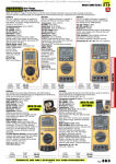
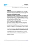
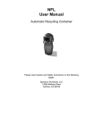
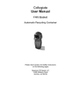
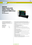
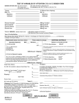
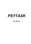
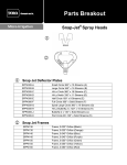
T.O.V.A. Synchronization Interface
The TOVA Company
T.O.V.A. Synchronization Interface
Andrew Greenberg, MS
The TOVA Company
3321 Cerritos Avenue
Los Alamitos, CA 90720 USA
Phone:
Fax:
Referrals:
Email:
Web:
800.PAY.ATTN or 800.729.2886 or 562.594.7700
800.452.6919 or 562.594.7770
800.REF.TOVA or 800.733.8682
[email protected]
http://www.tovatest.com/
c Copyright 2013-2015 The TOVA Company, All Rights Reserved.
Test Of Variables of Attention (abbreviated T.O.V.A.) is a registered trademark of The TOVA Company.
No part of this manual may be distributed without permission of The TOVA Company.
Orders of this manual should be directed to:
The TOVA Company
3321 Cerritos Avenue
Los Alamitos, CA 90720, USA
800.PAY.ATTN 800.729.2886 +1.562.594.7700
Fax 800.452.6919 +1.562.594.7770
Printed in the United States of America.
Contents
Introduction
1
System Requirements . . . . . . . . . . . . . . . . . . . . . . . . . . . . . . . . . . . . . . . . . . . . . . .
1
What’s in the T.O.V.A. sync interface kit? . . . . . . . . . . . . . . . . . . . . . . . . . . . . . . . . . . . . .
2
Setup and Testing
2
Setting up and configuring your T.O.V.A. sync interface . . . . . . . . . . . . . . . . . . . . . . . . . . . . .
2
Testing your sync interface . . . . . . . . . . . . . . . . . . . . . . . . . . . . . . . . . . . . . . . . . . . .
3
Output Modes: Digital or Analog
Digital output mode
3
. . . . . . . . . . . . . . . . . . . . . . . . . . . . . . . . . . . . . . . . . . . . . . . .
4
Output bits . . . . . . . . . . . . . . . . . . . . . . . . . . . . . . . . . . . . . . . . . . . . . . . . . .
4
‘Vout’: Customizable output high logic level . . . . . . . . . . . . . . . . . . . . . . . . . . . . . . . .
4
Analog output Mode . . . . . . . . . . . . . . . . . . . . . . . . . . . . . . . . . . . . . . . . . . . . . . . .
5
Decoding the analog output voltage . . . . . . . . . . . . . . . . . . . . . . . . . . . . . . . . . . . .
5
Physical Interfaces (Connectors)
6
Sync interface main connector . . . . . . . . . . . . . . . . . . . . . . . . . . . . . . . . . . . . . . . . . .
6
Standard breakout board . . . . . . . . . . . . . . . . . . . . . . . . . . . . . . . . . . . . . . . . . . . . .
7
Ribbon cable . . . . . . . . . . . . . . . . . . . . . . . . . . . . . . . . . . . . . . . . . . . . . . . . . . . .
8
Isolated breakout board . . . . . . . . . . . . . . . . . . . . . . . . . . . . . . . . . . . . . . . . . . . . . .
8
i
Introduction
The T.O.V.A. Synchronization Interface, or ‘sync interface’, is an add-on to the standard T.O.V.A. 8 system that
allows T.O.V.A. users to synchronize events in the T.O.V.A. test with other laboratory equipment. The sync interface
gets event messages from the T.O.V.A. USB device and formats the event information into a digital or analog output.
The user’s laboratory equipment (e.g., EEG equipment) then records this sync interface’s outputs on 1 - 4 auxiliary
input channels. By recording T.O.V.A. events in the raw data stream of the user’s equipment, the two devices can
now be precisely correlated in time.
Note that the sync interface does not record data; it is an output-only device.
A classic example of this setup would be connecting the T.O.V.A. sync interface to an EEG system, administering
the T.O.V.A., and then looking at the timing, amplitude, and other aspects of the P300 response to the T.O.V.A.
test’s target and nontarget stimuli.
Figure 1: The T.O.V.A. Synchronization Interface
System Requirements
• A fully working T.O.V.A. 8 installation on a Windows, Macintosh, or Linux PC. For T.O.V.A. 8 system requirements, please see the T.O.V.A. User’s Manual or the T.O.V.A. website at http://www.tovatest.com/.
• A synchronization-enabled T.O.V.A. USB device (see Figure 2). Synchronization-enabled USB devices have
two ‘microswitch ports’ on their front face panel, instead of the usual one. The sync-enabled USB device
should be provided as part of the sync interface kit.
• Data acquisition equipment with either of the following:
– 1 - 4 digital inputs that can record a user-selectable digital high level of more than 32 mV but less than
5.0V.
– 1 analog auxiliary input channel that can record a user-selectable maximum analog voltage of more
than 32 mV but less than 5.0V.
1
Figure 2: T.O.V.A. USB device with extra front panel connector)
What’s in the T.O.V.A. sync interface kit?
• The T.O.V.A. synchronization interface
• A standard breakout board
• An opto-isolated breakout board
• An 18-inch ribbon cable
Setup and Testing
WARNING: The sync interface will automatically output events during the practice test and T.O.V.A. test. Please
configure your sync interface BEFORE connecting it to your lab equipment.
Setting up and configuring your T.O.V.A. sync interface
Figure 3: Configuring the Sync Interface
2
1. If not installed already, install the T.O.V.A. 8 system according to the T.O.V.A. 8 Installation Guide (or User’s
Manual) and verify its operation.
2. Plug the T.O.V.A. sync interface into an open connector on the front panel of the T.O.V.A. USB device. Both
front panel connectors are equivalent, so it doesn’t matter which connector the sync interface or T.O.V.A.
microswitch is plugged into.
3. Run the T.O.V.A. and choose ‘Preferences’ on the main window.
4. In the Preferences dialog, choose the ‘Advanced’ tab and ‘Sync Interface’.
5. Choose digital or analog output modes, and set the maximum output voltage ‘Vout’ appropriate to your
equipment. Please read the Output Modes section (page 3) to help you choose which mode you want to
use.
6. The sync interface is now configured. The sync interface will automatically output events during both the
practice test and T.O.V.A. test.
Testing your sync interface
Figure 4: Testing the Sync Interface
1. Choose ‘Help’ on the main window, ‘Check T.O.V.A. Hardware’, ‘Sync Control’.
2. Verify your output mode and ‘Vout’ setting displayed in this dialog.
3. Click on any of the four output checkboxes to activate the outputs of the sync interface. You should be able
to confirm with your equipment (or a volt meter) that the output is on.
Output Modes: Digital or Analog
The sync interface can be set in one of two output modes: digital or analog. To change output modes, first make
sure the T.O.V.A. sync interface is plugged into the T.O.V.A. USB device, choose ‘Preferences’ from the T.O.V.A.’s
main window, ‘Advanced’, ‘Sync Interface’.
3
Digital output mode
In digital output mode, the T.O.V.A. testing events are given as active-high logic levels on four output bits. The user
can select the logic high level voltage from 32 mV to 5.0 V, which allows the sync interface to be compatible with
standard logic levels (5 V, 3.3V, 1.8V, etc).
Output bits
Table 1 describes the four output bits that are asserted in the digital output mode. Figure 5 shows an example of
how these bits correlate to various T.O.V.A. test events.
Bit Number
Label
Description
B0
‘Testing’
Administering test: this bit is it high (1) when the test is being
administered, and low (0) before and after the test, as well as
during a pause due to some user interrupt or hardware error.
B1
‘Target’
Target/Nontarget: this bit is high (1) when the stimulus being displayed is a target, and low (0) when the stimulus being displayed is
a nontarget. Note that this signal is only asserted when ‘stimulus
on’ is high.
B2
‘Stimulus on’
Stimulus on: this bit is high (1) when the stimulus is displayed.
This means either the visual stimulus displayed on the monitor or
the auditory stimulus being played on the speakers. This bit is low
(0) when the stimulus is not being displayed.
B3
‘Microswitch’
Microswitch pressed: this bit is high (1) when the microswitch is
being pressed, and low (0) when the microswitch has been released.
Table 1: Digital output bits
‘Vout’: Customizable output high logic level
In digital output mode, the logic low level an is obvious 0V (‘ground’). The logic high level can be set to any voltage
from 32 mV to 5.0V in 4 mV increments in order to make it compatible with various families of digital logic. This
setting is called ‘Vout’. To change Vout, first make sure the T.O.V.A. sync interface is plugged into the T.O.V.A. USB
device, choose ‘Preferences’ from the T.O.V.A.’s main window, ‘Advanced’, ‘Sync Interface’.
4
Figure 5: Digital Output Mode
Analog output Mode
In analog output mode, all four bits of the sync interface are combined together on one analog output line that
ranges in voltage from 0V to the customizable maximum output voltage, ‘Vout’. Vout can be set from 32 mV to
5.0V in steps of 4 mV. To change Vout, first make sure the T.O.V.A. sync interface is plugged into the T.O.V.A. USB
device, choose ‘Preferences’ from the T.O.V.A.’s main window, ‘Advanced’, ‘Sync Interface’.
The four output bits are combined to create Vout according to Equation 1.
Vout = (8 ∗ B3) + (4 ∗ B2) + (2 ∗ B1) + (1 ∗ B0)
Figure 6 shows an example of how the analog output varies given T.O.V.A. test events.
Decoding the analog output voltage
Use the algorithm in Equation 2 to decode the sampled analog voltage back into four output bits.
5
(1)
Figure 6: Analog Output Mode
bits = round
(Analog voltage @ Vout pin)
(Vout setting in volts) ∗ 0.0625
B3 = bits mod 8
B2 = (bits − (B3 ∗ 8)) mod 4
(2)
B1 = (bits − (B3 ∗ 8) − (B2 ∗ 4)) mod 2
B0 = (bits − (B3 ∗ 8) − (B2 ∗ 4) − (B2 ∗ 2)
Physical Interfaces (Connectors)
There is one main connector and four accessory options for electrically connecting the sync interface to your
equipment.
Sync interface main connector
Figure 7 shows the main connector on the sync interface and its pin out. The connector is a male, 2 X 5, 0.1-inch
keyed header, Sullins SBH11-PBPC-D05-RA-BK (Digi-Key S9177-ND). While any generic female, 2 X 5, 0.1-inch
header will mate with this connector, we strongly recommend using a keyed connector, such as the Sullins SFH11PBPC-D05-RA-BK (Digi-Key S9202-ND).
6
The entire even row (pins 2,4,6,8,10) are ground in order to separate each signal with a ground if a ribbon cable is
used (see ‘Ribbon cable’, page 8).
Figure 7: T.O.V.A. Sync Interface: Main connector
Standard breakout board
To facilitate quick and easy connections to the sync interface, we’ve provided a simple breakout board (Figure 12).
The breakout board uses the mating Sullins SFH11-PBPC-D05-RA-BK (Digi-Key S9202-ND) female connector
and breaks out the pins to a standard 0.2-inch-spaced “Euroterminal” breakout connector.
Figure 8: Photograph of the standard breakout board
Figure 9 shows its very simple schematic.
7
Figure 9: Schematic of the standard breakout board
Ribbon cable
Included in the T.O.V.A. Synchronization Interface kit is a 10-position ribbon cable (Digi-Key H3AAH-1018G).
Shown in Figure 10, this cable can be used either as a ribbon cable to reach another board, or it can be cut
in half, stripped, tinned, and used as a direct connection to other equipment.
Figure 10: Ribbon cable included in kit
Figure 11 has the pin out of the stripped cable.
Isolated breakout board
The opto-isolated breakout board is available for instrumentation that requires separate grounds from the T.O.V.A.
testing computer. Equipment sensitive to noise and ground loops, such as non-isolated EEG equipment, may need
to use the opto-isolated breakout board.
There are some requirements to using the isolated breakout board:
• Only the digital output mode is supported (see note below).
– To change the output mode to digital, first make sure the T.O.V.A. sync interface is plugged into the
8
Figure 11: Cut, stripped, and tinned ribbon cable example (with pinout)
T.O.V.A. USB device, choose ‘Preferences’ from the T.O.V.A.’s main window, ‘Advanced’, ‘Sync Interface’, and select the ‘Digital’ output mode.
• Vout must be set to 250 (5.0V) (see note below).
– To change Vout to 5.0V, first make sure the T.O.V.A. sync interface is plugged into the T.O.V.A. USB
device, choose ‘Preferences’ from the T.O.V.A.’s main window, ‘Advanced’, ‘Sync Interface’, and
enter ‘5.0’ in the Vout voltage entry field.
• The isolated board only provides open collector (‘OC’) outputs. This means that the outputs are only actively
pulled low, and require pull-up resistors to be pulled high. The isolated breakout board provides 10KΩ
pull-up resistors that are all connected to the ‘Vin’ pin via a 0.1-inch pin header that has shorting jumpers
pre-installed. To disable these pull-up resistors, simply pull off the shorting jumpers. Finally, the user must
provide the appropriate voltage for their high logic level at the pin ‘Vin’ in order for the pull-up resistors to
work.
Figure 13 shows its schematic.
Users who require an isolated analog output should contact T.O.V.A. technical support for information on a circuit
that will convert the isolated digital outputs into an isolated analog voltage.
9
Figure 12: Photograph of the isolated breakout board
Figure 13: Schematic of the isolated breakout board
10