1
Biomedical Embedded Systems Technology School of Engineering Science Simon Fraser University Burnaby, BC February 8, 2010
Dr. Andrew Rawicz
School of Engineering Science
Simon Fraser University
Burnaby, BC
V5A 1S6
Re: ENSC 440 Functional Specifications for Biomedical Monitoring System
Dear Dr. Rawicz:
Please see attached for Functional Specifications for Biomedical Monitoring System. Our product
is a data acquisition system to monitor patients’ cardiovascular health. The monitoring can be
done via two options: USB cable or through a wireless protocol.
The Document outlines an overview of the system functionalities of our product, Biomedical
Monitoring System (BMS), for both the proof of concept and production phases.
Biomedical Embedded Systems Technology (BEST) is a group of innovative engineering
students from diverse backgrounds. The team consists of Sam Seyfollahi and Alireza Rahbar
(Electronics Engineers), Farzad Abasi (Computer Engineer), Parna Niksirat (Systems Engineer),
and Shaghayegh Hosseinpour (Biomedical Engineer).
For any further information please feel free to contact me.
Yours truly,
TÄ|Üxét et{utÜ
Alireza Rahbar
President and CEO, BEST
Phone: (604) 339-4715
Email: [email protected]
Enclosure: Functional Specification for a Biomedical Monitoring System
Biomedical Embedded Systems Technology School of Engineering Science Simon Fraser University Burnaby, BC Functional Specifications for: Biomedical Monitoring System Project Team:
Alireza Rahbar
Farzad Abasi
Parna Niksirat
Shaghayegh Hosseinpour
Sam Seyfollahi
Contact Person:
Sam Seyfollahi
[email protected]
Submitted to:
Dr. Andrew Rawicz – ENSC 440
Steve Whitmore – ENSC 305
School of Engineering Science
Simon Fraser University
Due date: February 8, 2010
Revision: 1.0
Biomedical Embedded Systems Technology School of Engineering Science Simon Fraser University Burnaby, BC Executive Summary
Cardiovascular diseases (CVDs) are the number one cause of death worldwide [1]. To assist
doctors in the early detection of CDVs, Biomedical Embedded Systems Technology (BEST) is
developing an advanced heart monitoring system named the Biomedical Monitoring System
(BMS). This device is a portable, real time data acquisition system that is capable of acquiring
the electrocardiograph, heart rate, and body temperature of a patient. This information can
provide doctors key information which can aide in the diagnosis of underlining heart conditions.
The statistics gathered by BMS would have traditionally required days of hospital observations
or the use of expensive and uncomfortable equipment. BMS will provide accurate results while
maintaining the comfort of the patient.
The work required to create this system will be distributed evenly such that all members will
have a chance to work on the hardware, backend and the graphical user interface (GUI) of the
system. This will be accomplished by splitting the project up into three phases.
Phase one will be the design and implementation of the hardware. This phase will simply involve
interfacing the individual components (such as sensors and modules) together. By the end of
phase one the hardware of the BMS will be completely operational. We will also ensure that our
product is safe to use and complies with the medical equipment standards of North America.
This is to make sure that we can provide both accurate and reliable results while protecting the
user from harm.
Phase two is development of the core backend software. This is the most significant phase of our
project and involves developing:
•
Device drivers
•
Core data acquisition functionality
•
Data transmission functionality
•
Host computer software responsible for communication with the system.
We will also calibrate the sensors in this phase and make sure the readings obtained are within
acceptable thresholds. By the end of phase two, the system will be fully operational and will be
able to transmit the raw data to the host computer.
Phase three is the development of the GUI. This phase will involve writing the software to
interpret the raw data acquired by the system. By the end of this phase, the user will be able to
view the results of the system in an easy to read format such a graph, chart or table. The system
will also be able to transmit data to the host computer in real time so that the use can view live
results.
i Biomedical Embedded Systems Technology School of Engineering Science Simon Fraser University Burnaby, BC Table of Contents
Executive Summary........................................................................................................................................ i
Table of Contents............................................................................................................................................ ii
List of Figures.................................................................................................................................................. ii
Glossary............................................................................................................................................................ iii
1. Introduction ................................................................................................................................................ 1
1.1. Scope…...........................................................................................................................................1
1.2. Intended Audience........................................................................................................................ 1
1.3. Classification.................................................................................................................................. 2
2. System Requirements .............................................................................................................................. 2
2.1. System Overview…...................................................................................................................... 2
2.2. Overall System Requirement....................................................................................................... 3
2.3. Physical Requirement................................................................................................................... 3
2.4. Electronic Requirement................................................................................................................4
2.5. Communication Requirement......................................................................................................4
2.6. Mechanical Requirement............................................................................................................. 4
2.7. Environmental Requirement....................................................................................................... 4
2.8. Performance Requirement........................................................................................................... 4
2.9. Reliability and Durability..............................................................................................................5
2.10. Safety Requirement......................................................................................................................5
2.11. Luxury Requirement....................................................................................................................5
3. EKG/ECG Sensors......................................................................................................................................6
3.1. General Requirement....................................................................................................................6
3.2. Physical Requirement....................................................................................................................6
3.3. Safety Requirement........................................................................................................................7
4. Wireless Module .........................................................................................................................................7
4.1. General Requirement....................................................................................................................7
4.2. Electrical Requirement..................................................................................................................7
5. Micro-controller Board.............................................................................................................................8
5.1. General Requirement....................................................................................................................8
5.2. Environmental Requirement........................................................................................................8
5.3. Safety Requirement........................................................................................................................8
6. Graphical User Interface (GUI).............................................................................................................9
6.1. General Requirement....................................................................................................................9
7. User Documentations ................................................................................................................................9
8. System Test Plan.......................................................................................................................................10
9. Conclusion...................................................................................................................................................11
10. References.................................................................................................................................................12
List of Figures
Figure 1: System Overview.……...…………………………………………………………….…..2
Figure 2: Modified Waterfall Model ….………………………………………………………......10
ii Biomedical Embedded Systems Technology School of Engineering Science Simon Fraser University Burnaby, BC Glossary
-
CVD: Cardiovascular disease
-
GUI: Graphical User Interface
-
BEST: Biomedical Embedded Systems Technology
-
BMS: Biomedical Monitoring System
-
MUT: Module Under Test
-
USB: Universal Serial Bus
-
ECG/ EKG: Electrocardiography
iii Biomedical Embedded Systems Technology School of Engineering Science Simon Fraser University Burnaby, BC 1. Introduction
Biomedical Monitoring System is a wireless monitoring system that is used for screening and
diagnosis of heart diseases. This system is easy and convenient to use in the house or fitness
centre and can be used for remote real time monitoring. The patient either can be monitored
remotely by the doctor, or the data acquired by the system can be transferred through the use of
USB cable at a later time. The Biomedical Monitoring System shows the length of time required
for an electrical impulse to travel through the heart. A graph can be generated from the data
taken from the sensors and it can predict future heart failures. The functional requirements of the
Biomedical Monitoring System, as proposed by Biomedical Embedded System Technology, are
outlined in the following functional specification.
1.1. Scope
The scope of this document is to outline the functional requirement of the Biomedical
Monitoring System. This document describes the functionality of the system including sensors,
user interface, microcontroller, USB daughter board, wireless module and the overall system
functionality. This document also discusses all detailed function requirements which will be used
as a reference guide during the development as well as testing to ensure a safe and reliable
product. The specifications or design of some modules may change during the testing stage in
order to maximize the performance of the system.
1.2. Intended Audience
This document is intended for the Biomedical Embedded System Technology design engineers.
They should refer to this document in every stage of development to guarantee that the final
design meets the predefined function requirements. In addition, this document will provide the
marketing departments a better understanding of the Biomedical Monitoring System product
which makes it easier to advertise or find investors for the finalized product.
© Copyright 2010, BEST
February 2010
1 Biomedical Embedded Systems Technology School of Engineering Science Simon Fraser University Burnaby, BC 1.3. Classification The numbering convention of this document is as follows:
[Rn-p] A functional requirement specification.
‘R’ is an abbreviation for requirement, ‘n’ is the functional requirement number and ‘p’ stands
for one of the three development phase: I. Proof-of-concept stage.
II. Ongoing developing stage
III. Final production stage
2. System Requirements
Biomedical Embedded Systems Technology (BEST) is devoted to improving the quality and
accuracy of heart monitoring system as well as improving the quality of life for patients suffering
from heart diseases. The general requirements of the Biomedical Monitoring System are
presented in this section. The system overview describes the project at a glance. Next, the
systems' functional specifications are described in detail.
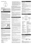
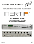
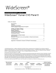
2.1 System Overview
The following (Figure 1) shows the system overview. The core of the system is an Atmel
microcontroller which will interface multiple sensors and modules together. These sensors will
collect raw data for the controller to interpret and convert to a more user readable format (such as
a graph). This data can be retrieved to a computer using either a USB cable or wirelessly.
Figure 1: System Overview
© Copyright 2010, BEST
February 2010
2 Biomedical Embedded Systems Technology School of Engineering Science Simon Fraser University Burnaby, BC Following (Figure 1 from the left) shows that the Sensors are connected to the patient’s body.
The sensors then transmit the analog signals to the processing unit. The microcontroller then
evaluates the information and stores the results. This data can then be transferred to a computer
either using a USB cable or wirelessly. This allows the physicians to monitor the condition of
their patients remotely. One of the most important factors for the Biomedical Monitoring System
that needs to be considered is the comfort of the user during the testing. The goal is to make it
easy to use, comfortable to wear and light to carry.
The functional specification for the overall system standards and regulations, microcontroller,
USB, Daughter Board, GUI, wireless, sensors, documentation, and test plans are described in
details respectively in the following sections.
2.2 Overall System Requirement
[R1-II]
BMS has to be wireless, easy to carry, and light weight.
[R2-II]
BMS has to be user interface friendly
[R3-III]
The price of the finalized system shall be under CDN$300.
[R4-III]
The output data has to be accurate and precise.
[R5-III]
The system should be safe to use and meet medical equipment standards of North
America.
2.3 Physical Requirements
[R6-I]
The finalized system should be pocket size and easy to carry.
[R7-II]
The weight of the finalized system should be not more than 300 g.
[R8-II]
The system should be integrated into one package.
[R9-II]
The system should also provide fitness monitoring.
[R10-III]
Connecting cables should be flexible and soft.
© Copyright 2010, BEST
February 2010
3 Biomedical Embedded Systems Technology School of Engineering Science Simon Fraser University Burnaby, BC 2.4 Electronic Requirements
[R11-III]
2.4GHz XBee XB24 is required to be connected to 3.3V at 40mA.
[R12-III]
The device should have portable power source.
[R13-I]
The system should operate in a low range of power.
2.5 Communication Requirement
[R14-II]
2.4GHz XBee is required to allow a very reliable and simple communication
between the microcontrollers and the host computer.
2.6 Mechanical Requirements
[R15-II]
The sensors connect to the controller via eight pin cable.
[R16-II]
The case of the entire system has to be waterproof.
2.7 Environmental Requirements
[R17-I]
The device should operate reliably from -10 to 45 degrees Celsius.
[R18-II]
The system should not be disturbed by high frequency signals.
[R19-I]
The device shall operate within electrical noise.
2.8 Performance Requirements
[R20- I]
The data acquired from sensors has to be accurate within ± 10% for all conditions.
[R21-II]
The final product heart rate sensor should have an accuracy of ± 2% for all
conditions.
[R22-I]
The process time for the data display has to be less than 50 ms.
[R23-I]
The Xbee wireless should be able to transmit up to 400ft (120m).
© Copyright 2010, BEST
February 2010
4 Biomedical Embedded Systems Technology School of Engineering Science Simon Fraser University Burnaby, BC 2.9 Reliability and Durability
[R24-II]
The device has to be able to withstand daily usage.
[R25-II]
BEST shall provide product warranty for two years.
[R26-III]
The device will be serviceable by company trained technician.
[R27-II]
The custom application must not interfere with normal computer operation.
2.10 Safety Requirements
[FR28-I]
Failure of the hardware will not cause any danger for the user.
[FR29-I]
The device should adhere to Canadian CAN/CSA-ISO 13485 standards for
medical devices.
[R30-II]
The system should not explode or leak any hazardous material.
2.11 Luxury Requirements
[R31-III]
The overall system package should be clean and attractive.
© Copyright 2010, BEST
February 2010
5 Biomedical Embedded Systems Technology School of Engineering Science Simon Fraser University Burnaby, BC 3. EKG/ECG SENSOR
ECG/EKG stands for Electrocardiography which is a test that measures electrical activity of the
heart using electrodes placed on the skin of the patient. With each heartbeat, an electrical pulse
travels through the heart. As a consequence the impulse (wave) causes the muscle to squeeze and
pump blood. The EKG sensor measure the voltage produces during contraction of the heart and
outputs a signal to the microcontroller.
The functional requirements for EKG/ECG sensor are specified as per following sub-sections:
3.1. General Requirements
[R32- I]
Three shielded leads: right, left and ground are required for an EKG sensor. An
electrolyte solution/jelly is placed on the surface of the electrode that comes in
contact with tissue. The other side of the sensor consists of a conductive metal
attached to a lead. This is the lead which is connected to the microcontroller.
[R33-I]
The signals coming from the wire of the intermediate connector are amplified.
[R34-I]
The signal is filtered in order to minimize the distortion.
[R35-I]
The heart rate signals from the electrodes are converted to digital information by
microcontroller.
3.2. Physical Requirements
[R36- I]
Silver Chloride should use to attach the electrodes to the skin and also aid in
electrical conduction.
[R37- I]
Cables connecting the electrodes to the processing unit shall be soft, flexible and
have sufficient length.
[R38-II]
The wires should have minimal movement while attached to the patient in order
to achieve higher accuracy.
[R39-I]
The electrode patch should make good contact with the skin to obtain a better
signal.
© Copyright 2010, BEST
February 2010
6 Biomedical Embedded Systems Technology School of Engineering Science Simon Fraser University Burnaby, BC 3.3. Safety Requirements
[R40-I]
The ground lead should be always connected on the body before connecting the
negative or positive lead.
[R41-I]
The sensor unit should be properly insulated to prevent a short circuit or electric
shock.
4. Wireless Module
The main function of the wireless module is to transmit the data collected by the microcontroller
to the computer for further processing without having to deal with wires.
The functional requirements for wireless module are specified in the following sub-sections:
4.1. General Requirements
[R42- I]
SPI interface for connection to the RF modules shall be supported.
[R43- II]
The wireless transceiver device that is connected to the external antenna must be
capable of transmitting serial data between the microcontroller and the host
computer in a reliable way.
4.2. Electrical Requirements
[R44- I]
The wireless transceiver components must be able to operate from a single 3.3
VDC power supply.
[R45- II]
The wireless transmitter shall operate in low power sleep mode when not
transmitting data for a reduction in power consumption.
[R46- II]
The wireless receiver shall be powered by the USB.
© Copyright 2010, BEST
February 2010
7 Biomedical Embedded Systems Technology School of Engineering Science Simon Fraser University Burnaby, BC 5. Micro-controller board
5.1. General Requirements
[R47-I]
The operating voltage for the microcontroller shall not exceed 9 Volts.
[R48-I]
Microcontroller shall not consume more than 20mA in active mode.
[R49-I]
Microcontroller must have at least five 10-bit analog I/O channels (or pins) to
provide enough accuracy for readings.
[R50-I]
The controller should be able to use internal interrupts to read available sensor
data.
[R51-I]
Microcontroller must have large enough serial flash to store the sensor data for at
least 24 hours.
5.2. Environmental Requirements
[R52-I]
The controller should be operational in temperatures within the range -10 to 45
degrees Celsius.
[R53-II]
The enclosure of the microcontroller along with other components must be
waterproof and suitable for damp environments use.
5.3. Physical Requirements
[R54-II]
The dimensions of the microcontroller shall not exceed 10cm X 10 cm.
[R55-II]
The controller shall not weight more than 200g.
© Copyright 2010, BEST
February 2010
8 Biomedical Embedded Systems Technology School of Engineering Science Simon Fraser University Burnaby, BC 6. Requirements for Graphical User Interface (GUI)
6.1. General Requirements
[R56-II]
It should be easily installed.
[R57-II]
It must be compatible with common operating systems such as Windows XP,
Vista and 7.
[R58-II]
The GUI should be extremely user-friendly and anyone with basic computer
knowledge should be able to work with the program.
[R59-I]
The software must be programmed in C# or Java.
[R60-II]
The software should include a user manual that include installation process, using
the software, as well as description on how to attach sensors.
[R61-II]
The software should be delivered by a CD.
[R62-II]
The software should be able to print ECG graphs.
[R63-I]
The software shall warn the user to seek medical attention in case a life
threatening or serious heart problem.
7. User Documentation
[R64-III]
The user manual shall be written for non expert audience and assuming users have
a minimum knowledge of handling electronic devices.
[R65-III]
User manual shall be presented in French, Spanish, German, Japanese,
Traditional Chinese and Simplified Chinese other than English so the product can
compete in international markets
[R66-III]
User documentation shall construct a website, including user manual, general and
technical support information, and required drivers all written in English.
© Copyright 2010, BEST
February 2010
9 Biomedical Embedded Systems Technology School of Engineering Science Simon Fraser University Burnaby, BC 8. System Test plan
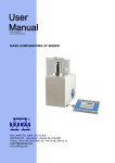
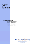
The life cycle of BMS will follow a slightly modified Waterfall model [2]. The Waterfall model
is a sequential software development process with the five main phases: requirement gathering,
design, implementation, verification and maintenance as shown in (Figure 2). We will use
modified version of this standard model which includes iteration at each step that will allow us to
go back up one or more previous steps in case problems are identified. This is done to ensure
each phase of the development is flawlessly implemented and to ensure a high degree of success.
Figure 2: Modified Waterfall Model
The majority of the testing for phase one will be done using lab equipment such as the
oscilloscope and voltmeters. BEST will ensure that the sensor readings obtained are within
specified fault tolerances. Since the majority of BMS is based on premade modules and
microcontrollers we do not expect to face many problems in this phase of the project.
Testing for phases two and three will be more involved and performed at several different levels.
First, the designer of each module under test (MUT) will perform white box testing on their own
work. Since the designer knows every function that is being tested, they should be able to test
each possible path independently without trouble.
Once the designer is comfortable with their MUT, the designer will pair up together with another
team member and they will perform black box testing on the other persons’ MUT. They will
attempt to give the module input that has not been handled without knowing how the internal
function itself is actually implemented.
© Copyright 2010, BEST
February 2010
10 Biomedical Embedded Systems Technology School of Engineering Science Simon Fraser University Burnaby, BC Third, the designer of the module will lead their partner though a short code review. This has the
double advantage that the partner can catch things that the designer may not have considered and
the partner will learn how the code works so at least two members of the team will have a
complete understanding of the system. This will help in situations where one team member may
be unavailable in case questions arise during development.
Finally, all modules will be integrated and tested after they have been merged in weekly
meetings. If at that point any issues arise, they should be small and easily remedied.
To ease the task of integration, BEST has created a subversion repository to be used for source
control. This will allow team members to independently work on their portion of code and merge
their code once complete. This will also allow us to revert to an older version of the code in case
a new piece of code causes problems.
In addition to the above, additional regression testing will be performed on the overall project to
make sure new features and code changes don’t introduce bugs in the system. This will be done
by using premade test cases that will be implemented using a scripting language.
Once the three phases of the project are complete, BEST will continue to maintain the code and
fix any bugs reported by the customers. BEST will also add improved functionality and features
once the base product is complete. This will ensure that the system will be reliable and useful for
many years down the road.
9. Conclusion
The functional specifications for Biomedial monitoring systems (BMS) have been presented in
this document. The requirements given in this document are tentative and will be modified as
needed during the completion of the project.
The final product will benefit not only health care providers, but also professional athletes. Our
product will make it easier for athletes to constantly monitor their performance and to help detect
early signs of heart failure. This system will be perfectly integrated, simple to use and to install.
We are certain that with the special features included in this system, our monitoring and
measuring system will stand out among all other competitors
We have divided the progress of the project into two separate phases. Our goal is to accomplish
all the related functional requirements for the proof-of-concept model outlined in this document
(marked by I or II) by target date of mid April 2010.
We at BEST hope these functional specifications will supply our audiences with necessary
required information regarding our product.
© Copyright 2010, BEST
February 2010
11 Biomedical Embedded Systems Technology School of Engineering Science Simon Fraser University Burnaby, BC 10. References:
[1] http://www.who.int/mediacentre/factsheets/fs317/en/index.html
[2] W. W. Royce, Managing the development of large software systems: concepts and
techniques, International Conference on Software Engineering Proceedings of the 9th
international conference on Software Engineering,1987 , Monterey, California, United States
© Copyright 2010, BEST
February 2010
12