1
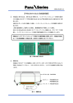
MICROCOMPUTER AM13L-STK2 Installation Manual Pub.No. 1174602-012E When you install each device after unpacking, please read this manual as a first step. This manual describes about unpacking, setting of each device, assembly, connection and startup. Please refer to other manual for the particular methods. Request for your special attention and precautions in using the technical information and semiconductors described in this book (1) If any of the products or technical information described in this book is to be exported or provided to non-residents, the laws and regulations of the exporting country, especially, those with regard to security export control, must be observed. (2) The technical information described in this book is intended only to show the main characteristics and application circuit examples of the products. No license is granted in and to any intellectual property right or other right owned by Panasonic Corporation or any other company. Therefore, no responsibility is assumed by our company as to the infringement upon any such right owned by any other company which may arise as a result of the use of technical information described in this book. (3) The products described in this book are intended to be used for general applications (such as office equipment, communications equipment, measuring instruments and household appliances), or for specific applications as expressly stated in this book. Consult our sales staff in advance for information on the following applications: Special applications (such as for airplanes, aerospace, automotive equipment, traffic signaling equipment, combustion equipment, life support systems and safety devices) in which exceptional quality and reliability are required, or if the failure or malfunction of the products may directly jeopardize life or harm the human body. It is to be understood that our company shall not be held responsible for any damage incurred as a result of or in connection with your using the products described in this book for any special application, unless our company agrees to your using the products in this book for any special application. (4) The products and product specifications described in this book are subject to change without notice for modification and/or improvement. At the final stage of your design, purchasing, or use of the products, therefore, ask for the most up-to-date Product Standards in advance to make sure that the latest specifications satisfy your requirements. (5) When designing your equipment, comply with the range of absolute maximum rating and the guaranteed operating conditions (operating power supply voltage and operating environment etc.). Especially, please be careful not to exceed the range of absolute maximum rating on the transient state, such as power-on, power-off and mode-switching. Otherwise, we will not be liable for any defect which may arise later in your equipment. Even when the products are used within the guaranteed values, take into the consideration of incidence of break down and failure mode, possible to occur to semiconductor products. Measures on the systems such as redundant design, arresting the spread of fire or preventing glitch are recommended in order to prevent physical injury, fire, social damages, for example, by using the products. (6) Comply with the instructions for use in order to prevent breakdown and characteristics change due to external factors (ESD, EOS, thermal stress and mechanical stress) at the time of handling, mounting or at customer's process. When using products for which damp-proof packing is required, satisfy the conditions, such as shelf life and the elapsed time since first opening the packages. (7) This book may be not reprinted or reproduced whether wholly or partially, without the prior written permission of our company. 20100202 If you have any inquiries or questions about this book or our semiconductor products, please contact our sales division. PanaXSeries is a registered trademark of Panasonic Corporation. Microsoft, Windows and the Windows logo are either registered trademarks or trademarks of Microsoft Corporation in the United States and/or other countries. DebugFactory is a registered trademark of Panasonic Corporation. DebugFactory Builder is a trademark of Panasonic Corporation. The other corporation names, logotype and product names written in this book are trademarks or registered trademarks of their corresponding corporations. About This Manual This manual is intended for engineers who will evaluate MN101LR05D using AM13L-STK2, which is a starter kit of microcomputer MN101LR05D with built-in ReRAM, and describes the installation method. Organization This manual mainly consists of four chapters of overview, software, hardware and appendix. The overview chapter describes a product outline and hardware functions of AM13L-STK2. The software chapter describes how to install the USB driver for connecting AM13L-STK2 with a host computer and how to install the debugger for AM13L-STK2(DebugFactory Builder for MN101_STK2). The hardware chapter describes details of each part and how to connect and how to customize the board. The appendix chapter shows a circuit diagram, a part list, and a dimensional drawing. Related Manuals We prepare the following manuals other than this manual about the product concerned. • "MN101LR05D LSI User's Manual" Describes characteristics and the control method of MN101LR05D. 4 Chapter 1 Overview Chapter 2 Software Chapter 3 Hardware Chapter 4 Appendix 1 2 3 4 Table of Contents Chapter 1 Overview ................................................................... 7 1.1 Product overview ...............................................................................................................8 1.1.1 Hardware Functions ....................................................................................................8 Chapter 2 Software.................................................................... 9 2.1 Installation .......................................................................................................................10 2.1.1 Checking Operating Environment.............................................................................10 2.1.2 Download of Software...............................................................................................10 2.1.3 Setup of the DebugFactory Builder for MN101_STK2 ............................................11 2.2 Installation of USB Driver...............................................................................................16 2.3 Safely Removing Hardware.............................................................................................18 2.4 Firmware Update Procedure ............................................................................................19 2.5 Checking Operations of DebugFactory Builder for MN101_STK2................................21 2.6 Debug Function List ........................................................................................................33 2.7 Notices for debugging with DebugFactory Builder for MN101_STK2..........................34 Chapter 3 Hardware ................................................................ 35 3.1 Part Names and Functions ...............................................................................................36 3.2 Debugger Connection ......................................................................................................42 3.3 Customization of AM13L-STK2.....................................................................................43 3.3.1 Use of Extension Terminals ......................................................................................43 3.3.2 Current Measurement ................................................................................................44 Chapter 4 Appendix ................................................................. 45 4.1 Circuit Diagram ...............................................................................................................46 4.2 Part List............................................................................................................................47 4.3 Dimensions ......................................................................................................................48 6 Chapter 1 Overview 1 Chapter 1 Overview 1.1 Product overview This product is the starter kit for evaluating microcomputer MN101LR05D with built-in ReRAM. You can evaluate microcomputer MN101LR05D with built-in ReRAM easily by connecting it with the USB port of the host computer directly and using the debugger for AM13L-STK2 (DebugFactory Builder for MN101_STK2). 1.1.1 Hardware Functions This section describes hardware functions of AM13L-STK2. Operating Voltage +4.7 V to +5.25 V Supplied from an USB bus power or an USB type AC adapter. +1.8 V to +3.6 V Supplied directly from an extension terminal of AM13L-STK2 to a microcomputer (a setting change on the board is needed). Mounted Microcomputer MN101LR05D Reset RC reset (the reset period is 500ms) Controllable Functions I/O port: 35 pins (all are dual purpose terminals.) LED (high-power) drive dual purpose terminal: 35 pins (2 pins are assigned to the LEDs on AM13L-STK2.) A/D input dual purpose terminal: 4 pins Timer input/output dual purpose terminal: 3 pins External interrupt dual purpose terminal: 6 pins Serial port dual purpose terminal: 5 pins (UART: 3 pin, I2C: 2 pin, both serves as synchronous serial ports.) LCD control terminal: 30 pins (4COM/26SEG) External Supply Voltage The voltage of +3.3 V and +5.0 V can be supplied from extension terminals of AM13L-STK2 to an external extension board. The total supply current is a maximum of 500 mA (current consumption of AM13L-STK2 is included.) 8 Product overview Chapter 2 Software 2 Chapter 2 Software 2.1 Installation 2.1.1 Checking Operating Environment Host Computer Specifications Table 2.1.1 Host Computer Specifications OS (Except virtual environment) Windows XP (after SP2) (32bit OS only) Windows Vista (32bit OS only) Windows 7 (32bit / 64bit OS) CPU Intel Pentium III 450 MHz or higher *including compatible CPU (Pentium III 1 GHz or higher recommended) Intel Pentium III 1GHz or higher *including compatible CPU Memory 256 MB minimum (512 MB or more recommended) 1GB or more Available hard disk space 400 MB minimum (1 GB or more recommended) Others with USB1.1/2.0 interface Note :The memory required depends on the size of the program to create. 2.1.2 Download of Software When developing and debugging software of AM13L-STK2, it is necessary to install the debugger for AM13L-STK2 (DebugFactory Builder for MN101_STK2). On the support page of Panasonic Microcomputer Technical Support <http://www.semicon.panasonic.co.jp/e-micom/support.html>, select "Starter kit", open the starter kit introduction page, and download the following programs. • DebugFactory Builder for MN101_STK2 (DFBuilder101_STK2_v4.6.4.1.EXE) Note :DebugFactory Builder for MN101_STK2 incorporates the product version compiler, assembler and linker. Therefore it is not necessary to install the compiler separately. 10 Installation Chapter 2 Software 2.1.3 Setup of the DebugFactory Builder for MN101_STK2 This section describes procedures of install the debugger for AM13L-STK2 (DebugFactory Builder for MN101_STK2). Note : - The installation must be done by members of the Administrators group. Users (including Power Users) who do not belong to the Administrators group cannot do this work. - Do not connect AM13L-STK2 to the host computer when installing DebugFactory Builder for MN101_STK2. 1. Double-click the icon of DebugFactory Builder for MN101_STK2 (DFBuilder101_STK2_v4.6.4.1.EXE) which has been downloaded, and start the DebugFactory Builder for MN101_STK2. (Refer to Figure 2.1.1.) Figure 2.1.1 Icon of DebugFactory Builder for MN101_STK2 2. When an installer program of DebugFactory Builder is executed, a dialog of Figure 2.1.2 appears. Select the language that you use the DebugFactory Builder for MN101_STK2. Figure 2.1.2 Selecting the language 3. After Setup program is started, the dialog shown in Figure 2.1.3 appears. Click <Next>. Figure 2.1.3 Starting of setting up DebugFactory Builder for MN101_STK2 Installation 11 Chapter 2 Software 4. The dialog shown in Figure 2.1.4 appears. Confirm the software license agreement, and click <Next>. Figure 2.1.4 Licence agreement of AM13L_STK2 5. The dialog shown in Figure 2.1.5 appears. Confirm the destination folder where the software tools will be installed, then click <Next>. If you want to install in a different folder, click <Change...> to specify the folder. Figure 2.1.5 Choose Destination Folder 12 Installation Chapter 2 Software 6. The dialog shown in Figure 2.1.6 appears. Click <Install>. Figure 2.1.6 Start Installation 7. The dialog shown in Figure 2.1.7 appears. Wait while DebugFactory Builder for MN101_STK2 installs. Figure 2.1.7 During installing of DebugFactory Builder for MN101_STK2 Installation 13 Chapter 2 Software 8. The dialog shown in Figure 2.1.8 appears. Click <Finish>. Figure 2.1.8 Setup Completed 9. After the installation is completed, [Panasonic DebugFactory Builder 4]-[MN101_STK2] group is registered in [All Programs] on the menu [Start]. Figure 2.1.9 shows the shortcut just registered. Figure 2.1.9 Registered [Panasonic DebugFactory Builder 4]-[MN101_STK2] Group 14 Installation Chapter 2 Software Table 2.1.2 Registered [Panasonic DebugFactory Builder 4]-[MN101_STK2] Group Shortcut name Description Builder Run the DebugFactory Builder for MN101_STK2. README Displays additional information and cautions not included in the manual. Help Displays Help of the DebugFactory Builder for MN101_STK2. Installation 15 Chapter 2 Software 2.2 Installation of USB Driver Connect the AM13L-STK2 to the host computer as shown in Figure 2.2.1. Connect to the USB port AM13L-STK2 Host computer Figure 2.2.1 Connecting AM13L-STK2 and the host computer If the USB driver is not installed in the host computer, after the AM13L-STK2 is connected, installation of the USB driver starts. Note : - Install DebugFactory Builder for MN101_STK2 before connecting the AM13L-STK2 to the host computer. For details about installation of DebugFactory Builder for MN101_STK2, refer to "2.1.3 Setup of the DebugFactory Builder for MN101_STK2 (p.11)". - The installation of USB driver must be done by members of the Administrators group. 1. The balloon hint is displayed at the lower right of the screen as shown in Figure 2.2.2. Figure 2.2.2 Installing device driver software After a while, the balloon hint is shown in Figure 2.2.3. Figure 2.2.3 Complete Installing Device Driver Software 2. When dialog box of Figure 2.2.4 is displayed after driver installation completion, restart of the host computer is necessary. 16 Installation of USB Driver Chapter 2 Software Figure 2.2.4 Restart of the host computer 3. From the [Start] menu, select [Control Panel], and click [System and Security], and click [Device Manager] to display the [Device Manager] window shown in Figure 2.2.5. Verify that "PanaX Onboard Tool Series" is listed in the "PanaXSeries" column. If it is not listed in the column, the USB driver might not have been installed properly. Verify that "PanaX Onboard Tool Series" is displayed. Figure 2.2.5 Device Manager Note : - Connecting the AM13L-STK2 to another USB port of the host computer or connecting other AM13L-STK2 to the USB port requires new installation of the USB driver. - Reinstalling the DebugFactory Builder for MN101_STK2 may require installation of the USB driver. Installation of USB Driver 17 Chapter 2 Software 2.3 Safely Removing Hardware This section describes how to remove the AM13L-STK2 connected to the host computer. 1. Right-click the [Safely Remove Hardware] icon in the notification area at the far right of the taskbar (the lower right of the screen). If the icon is not found, click the [Show hidden icons] button. Figure 2.3.1 Eject PanaX Onboard Tool Series 2. Select [Eject PanaX Onboard Tool Series], and verify that the message "The 'PanaX Onboard Tool Series' device can now be safely removed from the computer" is displayed as shown in Figure 2.3.2. Figure 2.3.2 Safe To Remove Hardware 3. Remove the AM13L-STK2 from the host computer as shown in Figure 2.3.3. Remove AM13L-STK2 Host computer Figure 2.3.3 Removing the AM13L-STK2 from the host computer 18 Safely Removing Hardware Chapter 2 Software 2.4 Firmware Update Procedure With DebugFactory Builder, when the error message "Please update the firmware because the firmware version is older. (Version: X.X.X)" appeared, it is necessary to update the firmware by following the procedures below. Figure 2.4.1 Firmware Version Error Note :Once updating the firmware, you can not back to the previous state. 1. The dialog shown in Figure 2.4.2 appears. Click <Yes>. Figure 2.4.2 Firmware Update Start Check 2. The dialog shown in Figure 2.4.3 appears. Click <OK>. Figure 2.4.3 Firmware Update Tool Start Check Note : - Do not connect multiple AM13L-STK2 to one host computer when updating the firmware. - Never remove the AM13L-STK2 from the host computer during updating the firmware. 3. The dialog shown in Figure 2.4.4 appears. Click <Update>. Click <Exit> to exit the update tool without updating the firmware. Firmware Update Procedure 19 Chapter 2 Software Figure 2.4.4 Startup Window of Firmware Update Tool 4. When <Update> is clicked, the display changes as shown in Figure 2.4.5. Wait until the firmware update has been completed. Figure 2.4.5 Firmware Update Tool Updating Screen 5. When the dialog shown in Figure 2.4.6 appears, the update has been completed. When the dialog shown in Figure 2.4.6 doesn't appear after 2 minutes or more, the firmware update has been failed. Figure 2.4.6 Completing Firmware Update Note : In case that the firmware update is failed, remove the AM13L-STK2 from the host computer immediately and contact to inquiries appears at the end of this manual. 20 Firmware Update Procedure Chapter 2 Software 2.5 Checking Operations of DebugFactory Builder for MN101_STK2 This section describes procedures for environment setting and checking operations of DebugFactory Builder for MN101_STK2. Startup From the menu [Start], select [All Program]-[Panasonic DebugFactory Builder 4]-[MN101_STK2], then click [Builder] contained in the [MN101_STK2] group to start up the DebugFactory Builder. (See "Registered [Panasonic DebugFactory Builder 4]-[MN101_STK2] Group" Figure 2.1.9(p.14).) If the software tools have been successfully installed, the startup window in Figure 2.5.1 appears. Figure 2.5.1 Startup Window Create the project and configure the settings to start DebugFactory Builder for MN101_STK2. Those can be easily performed through the [Project creation wizard] dialog. Select [New project creation] and click <OK> in [Startup window] shown in Figure 2.5.1, and the dialog shown in Figure 2.5.2 appears. Select [Standard], and click <Next>. Figure 2.5.2 Project creation wizard Checking Operations of DebugFactory Builder for MN101_STK2 21 Chapter 2 Software In this wizard, configure the settings for a project to be newly created. Here, configure only project settings to check operations, and use default settings for other items. Project name: Specify a project file name. Folder to save: Specify a destination folder. Source file to be added automatically: Check both [Startup assembler] and [Sample source file]. Specify a project file name Check the box Specify a destination folder Figure 2.5.3 Project setting In the Language tool setting, set "Use the built-in language tool" which is an initial value. If other language tools are used, set "Use a following language tool". Figure 2.5.4 Language tool setting 22 Checking Operations of DebugFactory Builder for MN101_STK2 Chapter 2 Software The dialog shown in Figure 2.5.5 appears. Click the <Set> button. Figure 2.5.5 Target setting Checking Operations of DebugFactory Builder for MN101_STK2 23 Chapter 2 Software Figure 2.5.6 appears in the <Set> button click. • Target setting dialog box (Target setting) Choose a product type to use. Leave the type of debugging tool "Starter kit". Table 2.5.1 shows the details of each setting item. Set Product type and Type Figure 2.5.6 Target setting dialog box Table 2.5.1 Target setting dialog (Target setting) 24 Product type Select "101LR05D". Type Select "Starter kit" as a target type. Stack pointer initial value Enters the default stack pointer as a hexadecimal value. If there is no special reason, don't change the setting. Special register routine file Special register addresses may be defined as symbols by specifying the file here in some product types. For details, refer to Help on DebugFactory Builder for MN101_STK2. User setting Set user original setting that is not included in the target setting dialog. If there is no special reason, it is not necessary to set it. Comment Describe comments for the target setting information. If there is no special reason, it is not necessary to set it. Checking Operations of DebugFactory Builder for MN101_STK2 Chapter 2 Software • Target setting dialog box (Starter kit) Select [Starter kit] tab sheet. The dialog box changes as shown in Figure 2.5.7. If there is no special reason, don't change the setting. Figure 2.5.7 Starter kit setting Table 2.5.2 Target Setting Dialog Box (Starter kit) Communication timeout time Specify a communication timeout. If there is no special reason, don't change the setting. Execution verification interval Specify the interval that the debugger checks states of the microcomputer during program execution. If there is no special reason, don't change the setting. Communication frequency Specify the communication frequency of the terminal for exclusive use of the debugging of the AM13L-STK2. If there is no special reason, don't change the setting. Checking Operations of DebugFactory Builder for MN101_STK2 25 Chapter 2 Software • Target setting dialog box (Flash memory setting) Select [Flash memory setting] tab sheet. The dialog box changes as shown in Figure 2.5.8. Set about debugging ReRAM. Figure 2.5.8 Flash memory setting Table 2.5.3 Target Setting Dialog Box (Flash memory setting) Enable software break to flash memory Enable the software break function to codes in ReRAM. Enable verify check to flash memory Perform verify check at programming to ReRAM. Click <OK> after setting. 26 Checking Operations of DebugFactory Builder for MN101_STK2 Chapter 2 Software After completing project settings and clicking <End>, the window shown in Figure 2.5.9 appears. Figure 2.5.9 Startup Window of DebugFactory Builder for MN101_STK2 The startup assembler and the sample source file set in the project creation wizard are added in the project, and the startup assembler is displayed in the [Code] window. The start-up assembler contains processing indispensable to describe a sample program by the C language using AM13L-STK2. The sample C source file describes the processing which blinks the green LED (D5) periodically. AM13L-STK2 is shipped in the state that these programs are written in the ReRAM. Checking Operations of DebugFactory Builder for MN101_STK2 27 Chapter 2 Software Make execution Select [Make]-[Make] in the main menu, then compiling and linking are performed. The message "Execution file has been created" is displayed in the [Make output] window shown in Figure 2.5.10, when the make is completed. Figure 2.5.10 Make output Verification Select [Debug]-[Debugging start] in the main menu as shown in Figure 2.5.11. When various settings are performed correctly, the message of "Start of the debug mode" is displayed in the command window as shown in Figure 2.5.12. Then debugging operation such as memory change and execution of the program on the device to be debugged becomes possible. If the command window is not displayed, select [Show]-[Window]-[Command] in the main menu. Figure 2.5.11 Selection of [Debugging Start] 28 Checking Operations of DebugFactory Builder for MN101_STK2 Chapter 2 Software "Start of debug mode" is displayed. Figure 2.5.12 Debug Mode Start Note : When an error message is displayed and a debug mode does not start successfully, select again [Debug]-[Debugging start] in the main menu after verifying relevant settings and the connection between the host computer and AM13L-STK2. Checking Operations of DebugFactory Builder for MN101_STK2 29 Chapter 2 Software If [Debug]-[Debugging end] in the main menu is selected as shown in Figure 2.5.13, the confirmation dialog of the debug mode exit (Figure 2.5.14) is displayed. When <OK> is clicked, the debug mode is exited.(Figure 1.5.15) Figure 2.5.13 Selection of [Debugging end] Figure 2.5.14 Confirmation of the Debug Mode Exit 30 Checking Operations of DebugFactory Builder for MN101_STK2 Chapter 2 Software "End of debug mode" is displayed. Figure 2.5.15 Debug Mode Exit Checking Operations of DebugFactory Builder for MN101_STK2 31 Chapter 2 Software Exit Select [File]-[Exit] in the main menu to exit the DebugFactory Builder for MN101_STK2. Figure 2.5.16 Exit of DebugFactory Builder for MN101_STK2 Remove AM13L-STK2 from the host computer. Remove AM13L-STK2 Host computer Figure 2.5.17 Removal of AM13L-STK2 32 Checking Operations of DebugFactory Builder for MN101_STK2 Chapter 2 Software 2.6 Debug Function List Table 2.6.1 shows the debug functions of the debugger for AM13L-STK2 (DebugFactory Builder for MN101_STK2). Table 2.6.1 Debug Function List Debug function Program load Description Writes a user program in a target memory Debugger for AM13L-STK2 Yes Program execution Executes normally Yes Microcomputer reset Resets to a microcomputer Yes Come execution Executes to the cursor position of the code window Yes Single step execution Executes step by step in units of a source line or an assembler Yes Function step execution Executes step by step regarding a subroutine as one step Yes Dump Dumps contents of a memory Yes Edit Modifies contents of a memory to a specified value Yes Edit (ReRAM) Modifies contents of a ReRAM memory to a specified value Yes Watch Indicates contents of a memory during program execution in specified form Conditional* Inspect Indicates in the form according to data structure of a specified variable Yes Register indication/modification Indicates/Modifies contents of a specified register Yes RAM monitor Indicates contents of a memory during program execution by sampling Back trace Executes a back trace of a stack frame and indicates a process in which a function has been called Yes Forced break Stops program execution by force Yes Software break Breaks at a maximum of 256 points Yes Instruction address break Breaks by address Yes Data access break Breaks by access width (1/2), address, data, data mask, NOT function Yes Uninstalled instruction Execution Data indication/modifi cation Break Conditional* Breaks when an uninstalled instruction is executed Yes Profile Measures the executing frequency of a subroutine/function Yes On the fly Sets a break, refers to a memory, and modifies a memory during program execution Yes *somewhat affected to program execution Debug Function List 33 Chapter 2 Software 2.7 Notices for debugging with DebugFactory Builder for MN101_STK2 • Don't remove the AM13L-STK2 while the target is connected in order to avoid improper operation of the debugger. When the debugger operates improperly, remove the AM13L-STK2 and restart DebugFactory Builder for MN101_STK2. 34 Notices for debugging with DebugFactory Builder for MN101_STK2 Chapter 3 Hardware 3 Chapter 3 Hardware 3.1 Part Names and Functions This section describes part names and functions of AM13L-STK2. Figure 3.1.1 shows a part arrangement plan of AM13L-STK2 on the top view, and Figure 3.1.2 shows a part arrangement plan of AM13L-STK2 on the bottom view. USB connecter (CN1) Extension terminal (CN3) J1 J3 J2 J4 MN101LR05D (IC1) Extension terminal (CN2) Green LED (D5) Orange LED (D4) Figure 3.1.1 Part Arrangement Plan (top view) Low-speed oscillation circuit (X1,C35,C36,R19) R6 R5 High-speed oscillation circuit (X2,C37,C38,R18) Figure 3.1.2 Part Arrangement Plan (bottom view) MN101LR05D(IC1) This is a microcomputer with built-in ReRAM to be evaluated. For characteristics and port control of MN101LR05D, refer to "MN101LR05D LSI User's Manual". Reset RC reset circuit by the built-in pull-up resistor of MN101LR05D (IC1) and the capacitor mounted on the board is implemented. The reset period is 500ms. When a switch reset is required separately, connect it to the No. 6 pin of the extension terminal (CN2). 36 Part Names and Functions Chapter 3 Hardware Low-speed oscillation circuit (X1, C35, C36, R19) This is outside low-speed oscillation circuit for MN101LR05D (IC1). Low-speed oscillation circuit is not mounted at board manufacture. Figure 3.1.3 shows a part arrangement plan of low-speed oscillation circuit. Low-speed oscillation circuit (X1, C35, C36, R19) X1 C3 C36 R19 Figure 3.1.3 Part Arrangement Plan of low-speed oscillation circuit Note :Confirm the frequency accuracy input low-clock depending on the usage of AM13L-STK2. High-speed oscillation circuit (X2, C37, C38, R18) This is outside High-speed oscillation circuit for MN101LR05D (IC1). High-speed oscillation circuit is not mounted at board manufacture. Figure 3.1.4 shows a part arrangement plan of High-speed oscillation circuit. R18 C37 X2 C38 High-speed oscillation circuit (X2, C37, C38, R18) Figure 3.1.4 Part Arrangement Plan of high-speed oscillation circuit Note :Confirm the frequency accuracy input high-clock depending on the usage of AM13L-STK2. LED (D4, D5) These can be controlled by a user program. Pins of IC1 assigned to D4 and D5 are indicated below. Orange LED (D4): No. 8 pin of IC1 (P00/TM9IOC) Green LED (D5): No. 9 pin of IC1 (P01/TM4IOC) USB connector (CN1) This is USB series A plug. In addition, AM13L-STK2 is compliant with USB2.0 standard and it supports Full Speed (12 Mbps) as the data transfer rate. Part Names and Functions 37 Chapter 3 Hardware Extension terminal (CN2, CN3) Use these terminals as functional extension terminals. Arrangement of the extension terminals is shown in Table 3.1.1. Table 3.1.2 shows function of extension terminals (CN2), and Table 3.1.3 shows function of extension terminals (CN3). Through holes of 2.54 mm pitch and φ0.9 mm hole diameter are prepared for connector mounting. To extend functions by using the extension terminals, refer to "3.3.1 Use of Extension Terminals (p.43)". Table 3.1.1 Arrangement of Extension Terminals CN3 15 CN3 18 CN3 20 CN3 22 CN3 24 CN2 26 CN2 24 CN2 22 CN2 20 CN2 18 CN2 15 38 CN3 14 CN3 17 CN3 19 CN3 21 CN3 23 CN2 25 CN2 23 CN2 21 CN2 19 CN2 17 CN2 14 Part Names and Functions CN3 13 CN3 16 CN2 16 CN2 13 CN3 12 CN2 12 CN3 11 CN2 11 CN3 10 CN2 10 CN3 9 CN2 9 CN3 8 CN2 8 CN3 7 CN2 7 CN3 6 CN2 6 CN3 5 CN3 3 CN2 3 CN2 5 CN3 4 CN3 2 CN3 1 CN2 1 CN2 2 CN2 4 Chapter 3 Hardware Table 3.1.2 Function of Extension Terminals (CN2) Pin number 1 2 3 4 5 6 7 8 9 10 11 12 13 14 15 16 17 18 19 20 21 22 23 24 25 26 Function VBUS VBUS VDD GND VDD NRST VLC1 VLC2 VLC3 GND P77/COM0 P76/COM1 P75/COM2 P74/COM3 GND P67/SEG4/SBCS0A/KEY7B P66/SEG5/SBT0A/KEY6B P65/SEG6/SBO0A/TXD0A/KEY5B P64/SEG7/SBI0A/RXD0A/KEY4B P63/SEG8/IRQ3B P62/SEG9/IRQ2B P61/SEG10/IRQ1B P60/SEG11/IRQ0B P57/TM8IOA/KEY3B/CLKOUTB P56/SEG13/TM3IOA/KEY2B P55/SEG14/TM1IOA/KEY1B Note :SEG12 of the LCD function connected to extension terminal (CN2) is unusable in AM13L-STK2. All LCD functions can be used on MN101LR05D provided without AM13L-STK2. Part Names and Functions 39 Chapter 3 Hardware Table 3.1.3 Function of Extension Terminals (CN3) Pin number 1 2 3 4 5 6 7 8 9 10 11 12 13 14 15 16 17 18 19 20 21 22 23 24 40 Part Names and Functions Function P10/A0/KEY0A/IRQ0A P11/A1/KEY1A/IRQ1A P12/A2/KEY2A GND P13/A3/KEY3A VREFP P22/SEG40/SBI2B P23/SEG39/SBO2B/SDA2B GND P24/SEG38/SBT2B/SCL2B P25/SEG37/SBCS2B P26/SEG36/SBI1A/RXD1A P30/SEG35/SBO1A/TXD1A P31/SEG34/SBT1A GND P32/SEG33/SBCS1A P45/SEG22/SBI1B/RXD1B P46/SEG21/SBO1B/TXD1B P50/SEG19/SBCS1B P47/SEG20/SBT1B P52/SEG17/SBO3B/SDA3B P51/SEG18/SBI3B P54/SEG15/SBCS3B/KEY0B P53/SEG16/SBT3B/SCL3B Chapter 3 Hardware Power supply switching jumper (J1) This is a jumper for switching a power supply of the board. When it short-circuits by solder mounting, the USB bus power drive is selected. When it opens by solder un-mounting, the external power drive which supplies a power from the No. 3 pin and No. 5 pin of the extension terminal CN2 is selected. The voltage which can be supplied to AM13L-STK2 from the No. 3 pin and No. 5 pin of the extension terminal CN2 is +1.8 V to +3.6 V. At board manufacture, the USB bus power drive is selected because it short-circuits. The debugger for AM13LSTK2 (DebugFactory Builder for MN101_STK2) can not be connected when the external power drive is selected. To connect the debugger for AM13L-STK2 (DebugFactory Builder for MN101_STK2), make the power supply switching jumper (J1) short-circuit to select the USB bus power drive. Current measurement jumper (J2) This is a jumper for measuring the current consumption of MN101LR05D (IC1). It short-circuits by solder mounting at board manufacture. To measure current, connect an ammeter after removing solder and confirming the polarity of the jumper. Refer to "3.3.2 Current Measurement (p.44)" for how to measure current. Power supply switching jumper for reference voltage of AD converter (J3) This is a jumper for switching a power supply of the No. 20 pin (VREFP) of MN101LR05D (IC1). It short-circuits by solder mounting at board manufacture. To supply power from the No. 6 pin of extension terminal (CN3) into the No. 20 pin (VREFP) of MN101LR05D (IC1), make sure to remove a solder before power supply. Power supply switching jumper for LCD (J4) This is a jumper for switching a power supply of the No. 77 pin (VLC1) of MN101LR05D (IC1). It short-circuits by solder mounting at board manufacture. To supply power from the No. 7 pin of extension terminal (CN2) into the No. 77 pin (VLC1) of MN101LR05D (IC1), make sure to remove a solder before power supply. Auto reset switching resistances (R5, R6) These are resistances for switching an input voltage of the No. 4 pin (NATRON) of MN101LR05D (IC1). To set the auto reset of MN101LR05D (IC1), change the mounting of R5 and R6. Relations of the auto reset and mounting of R5 and R6 are as follows. Auto reset OFF : R5 mount, R6 unmount Auto reset ON : R5 unmount, R6 mount Auto reset is OFF at board manufacture. Part Names and Functions 41 Chapter 3 Hardware 3.2 Debugger Connection For debugging and programming by AM13L-STK2, installation of the debugger for AM13L-STK2 (DebugFactory Builder for MN101_STK2) is needed. Refer to the software chapter for the installation method. Figure 3.2.1 shows the example of connection of the debugger for AM13L-STK2 (DebugFactory Builder for MN101_STK2). To connect the debugger for AM13L-STK2 (DebugFactory Builder for MN101_STK2), confirm that the power supply switching jumper (J1) short-circuits, and connect AM13L-STK2 to the USB port of the host computer. Connect to USB port AM13L-STK2 Host computer Figure 3.2.1 Example of Connection of the Debugger for AM13L-STK2 42 Debugger Connection Chapter 3 Hardware 3.3 Customization of AM13L-STK2 This section describes functional extension of AM13L-STK2 and customization at evaluation. 3.3.1 Use of Extension Terminals This section describes cautions at use of the extension terminals (CN2, CN3) and at creation of an extension board by the user. Cautions at Extension Terminal Mounting Mount connectors of 2.54 mm pitch on CN2 and CN3. Power Supply from AM13L-STK2 to the Extension Board AM13L-STK2 can supply the voltage of +5.0 V (VBUS) from No. 1 pin and No. 2 pin of CN2, and the voltage of +3.3 V from No. 3 pin and No. 4 pin of CN2. The total output current of +5.0 V and +3.3 V is a maximum of 500 mA including the current consumption of AM13L-STK2. Power Supply from the Extension Board to AM13L-STK2 AM13L-STK2 can operate by the power supply from the extension board. When the extension board supplies the operation power to AM13L-STK2, make the power supply switching jumper (J1) open, and make No.3 pin and No.5 pin of CN2 supply a voltage of +1.8 V to +3.6 V. The power supply to +3.3 V regulator (IC3) stops by making the power supply switching jumper (J1) open. Power supply from the extension board to reference voltage of AD converter When the extension board supplies the reference voltage of AD converter to AM13L-STK2, open the power supply switching jumper for reference voltage of AD converter (J3). Supply the reference voltage from No.6 pin of CN3. Reference voltage for AD converter of AM13L-STK2 make less than or equal the operating voltage of MN101LR05D (IC1). Power supply from the extension board to LCD When the extension board supplies a power to the No.77 pin (VLC1) of MN101LR05D (IC1), open the Power supply switching jumper for LCD (J4). Reset signal input from the extension board When the extension board input the reset signal to No. 5 pin (NRST) of MN101LR05D (IC1), make the reset signal from the extension board into open-drain output. Customization of AM13L-STK2 43 Chapter 3 Hardware 3.3.2 Current Measurement This section describes how to measure current consumed by MN101LR05D (IC1). The current measurement jumper (J2) which can measure the current consumption of MN101LR05D (IC1) is prepared on the board of AM13L-STK2. To measure current, remove the solder of a current measurement jumper (J2) to open, and connect an ammeter. Figure 3.3.1 shows the polarity of the current measurement jumper (J2). J2 - + Figure 3.3.1 Polarity of the Current Measurement Jumper (J2) Using the current measurement jumper (J2) can measure the sum of the core current consumption and the IO current consumption. 44 Customization of AM13L-STK2 Chapter 4 Appendix 4 Chapter 4 Appendix 4.1 Circuit Diagram Figure 4.1.1 shows the circuit diagram of AM13L-STK2. Figure 4.1.1 Circuit Diagram of AM13L-STK2 46 Circuit Diagram Chapter 4 Appendix 4.2 Part List Table 4.2.1 shows the part list of AM13L-STK2. Table 4.2.1 Part List of AM13L-STK2 Part Number Function Model number Maker IC1 Microcomputer MN101LR05D Panasonic IC2 USB-DWire converter IC MN101EF35G Panasonic IC3 +3.3 V regulator TLV1117-33CDCYR IC4 Reset IC MCP130T-300I/TT PDTC143ZE DT-26 D4 Digital Transistor Crystal Resonator for MN101LR05D (Low-speed) CL=6pF Crystal Unit for MN101LR05D (High-speed) Resonator for USB-DWire converter IC (8MHz) ESD protection diode for USB power ESD protection diode for USB data LED (Orange) TI MICRO CHIP NXP Number Mounting TQFP80-P-1212 1 Yes HQFP048-P-0707B 1 Yes SOT-223 1 Yes SOT23-3 1 Yes SC-75 2 Yes DAISHINKU Cylinder type 1 No CX3225GB10000D0HEQZ1 KYOCERA 3.20 mm x 2.50 mm 1 No CSTCE8M00G15L MURATA 3.2 mm x 1.3 mm 1 Yes NNCD5.6D-T1 NEC 1.6 mm x 0.8 mm 1 Yes LXES15AAA1-100 MURATA 1.0 mm x 0.5 mm 2 No D5 LED (Green) SML-310DT ROHM 1.6 mm x 0.8 mm 1 Yes SML-310MT ROHM 1.6 mm x 0.8 mm 1 CN1 Yes USB-A (male) A-USB A-LP-SMT ASSMANN 1 Yes CN2 Extension connector (26 pin) - - 1 No CN3 Extension connector (24 pin) - - 1 No R1 - R5 10 kΩ resistor - - 20.30 mm x 12 mm 2.54 mm pitch pin header 2.54 mm pitch pin header 1.6 mm x 0.8 mm 5 Yes R6 10 kΩ resistor - - 1.6 mm x 0.8 mm 1 No R11, R12 20 Ω resistor - - 1.6 mm x 0.8 mm 2 Yes Q1, Q2 X1 X2 X3 D1 D2, D3 Package size R13, R14 470 kΩ resistor - - 1.6 mm x 0.8 mm 2 Yes R15 1.5 kΩ resistor - - 1.6 mm x 0.8 mm 1 Yes R16 300 Ω resistor - - 1.6 mm x 0.8 mm 1 Yes R17 270 Ω resistor - - 1.6 mm x 0.8 mm 1 Yes R18 270 Ω resistor - - 1.6 mm x 0.8 mm 1 No R19 36 kΩ resistor - - 1.6 mm x 0.8 mm 1 No 0.11 uF ceramic capacitor - - 1.6 mm x 0.8 mm 7 Yes C21 - C27 C1 - C7 1 uF ceramic capacitor - - 1.6 mm x 0.8 mm 7 Yes C31, C32 4.7 uF ceramic capacitor - - 1.6 mm x 0.8 mm 2 Yes C35, C36 7 pF ceramic capacitor - - 1.6 mm x 0.8 mm 2 No C37, C38 10 pF ceramic capacitor - - 1.6 mm x 0.8 mm 2 No C41 - C44 0.22 uF ceramic capacitor - - 1.6 mm x 0.8 mm 4 Yes Part List 47 Chapter 4 Appendix 4.3 Dimensions Figure 4.3.1 shows the board dimensional drawing of AM13L-STK2. All units are millimeters. 80 Figure 4.3.1 Dimensional Drawing of AM13L-STK2 48 Dimensions 16 30 12 60 Record of Changes AM13L-STK2 Installation Manual Record of Changes Revised on April 26, 2013 Definition New Previous Edition (---) Page Section -- -- Details of Changes --- New Edition (1.1) Details of Changes New making of the manual Revised on September 2, 2013 Definition 50 Previous Edition (1.1) Page Section Change 8 29 Change 16 Change Details of Changes New Edition (1.2) Details of Changes LCD control terminal: 31 pins (4COM/27SEG) LCD control terminal: 30 pins (4COM/26SEG) Figure 2.2.1 --- Replaced a figure 18 Figure 2.3.3 --- Replaced a figure Change 32 Figure 2.5.17 --- Replaced a figure Change 39 Table 3.1.2 P57/SEG12/TM8IOA/KEY3B/CLKO P57/TM8IOA/KEY3B/CLKOUTB UTB Add 39 30 --- Note: SEG12 of the LCD function connected to extension terminal (CN2) is unusable in AM13L-STK2. All LCD functions can be used on MN101LR05D provided without AM13L-STK2. Change 42 Figure 3.2.1 --- Replaced a figure Inquiries If you have questions regarding technical information on this manual, please visit the following URL. Panasonic Corporation URL: http://www.semicon.panasonic.co.jp/en Microcomputer Home Page http://www.semicon.panasonic.co.jp/e-micom AM13L-STK2 Installation Manual September 2, 2013 1st Edition 2nd Printing Issued by Panasonic Corporation © Panasonic Corporation 2013 1 Kotari-yakemachi, Nagaokakyo City, Kyoto 617-8520, Japan Tel : 81-75-951-8151 http://www.semicon.panasonic.co.jp/en 010413 Printed in Japan