1
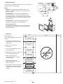
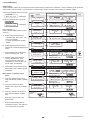
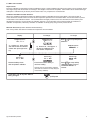
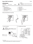
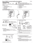
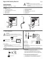
English
Signet 5900 Salinity Monitor
CAUTION!
• Refer to instruction manual for more details.
• Remove power to unit before wiring input and output
connections.
• Follow instructions carefully to avoid personal injury.
*3-5900.090-1*
3-5900.090-1
Rev. E 3/06
English
Contents
1.
2.
3.
4.
5.
6.
Power Connections
Compatible Sensor Wiring
4 - 20 mA Current Output Connections
Relay Connections
Relay Operation
Menu Functions
7.
8.
9.
10.
11.
12.
Temperature Coefficient
Parts and Accessories
Specifications
Quick Reference Menu Parameters
Troubleshooting
Maintenance
Remove terminal blocks for easy wiring
Std. Sensor
Open Collector
Sensor
12-24 V
10 W
UL
12-24 V
10 W
-
Silver (Shld)
Black
White
Red
External power supply
-
= DC or AC power
+
12 - 24 VDC
OR
12 - 24 VAC
Technical Notes:
• To reduce the possibility of noise interference, isolate AC
power lines from signal lines.
• Maximum 4-20 mA loop impedance is affected by the supply
voltage.
3. 4-20 mA Current Output Connections
4 - 20 mA*
+
*
5900 Terminals
5900
Terminals
Signet Sensor
3-2822-1 (10.0)
3-2823-1 (20.0)
Range (PPT):
0 - 80
PPT
Shld
-
= Double Insulated
4-20
mA
Open Collector
Sensor
10.0
10 W
+
2
Total
reset
2. Compatible Sensor Wiring
CAUTION!
Never connect 110 VAC or 220 VAC to rear power
terminals. High voltage AC will damage instrument and
void warranty.
12-24 V 5900 Terminals
-
LISTED
77CJ
+
-
20.0
Fuse**
1/8A
1
Std. Sensor
1. Power Connections
+
Gnd
Iso. Gnd
+
+
Signal IN
LISTED
77CJ
Gnd
Temp. IN
UL
+
PLS
AUX
output output
Flow
2
Total
reset
Patent No. D376,328
1
Freq. IN
Gnd
Freq. IN
+
Flow
Gnd
Patent No. D376,328
Freq. IN
Iso. Gnd
Sen. Pwr.
Freq. IN
+
PLS
AUX
output output
Iso. Gnd
3.
2.
Sen. Pwr.
1.
Technical Notes:
• Use three conductor shielded cable for cable extensions up to
30 m (100 ft) max.
• Cable shield MUST be maintained through cable splice.
Technical Notes:
** 1/8A fuse recommended (customer supplied)
* 4-20 mA output is internally powered (non-isolated),
maximum loop impedance 350 Ω with a 12 V instrument
supply voltage, 950 Ω with a 24 V instrument supply voltage.
To isolate output and prevent ground loop problems:
1. Use monitor device with isolated inputs, or
2. Use separate DC supply for 5900 and monitor device, or
3. Power 5900 with 12 - 24 VAC step down transformer
4. Relay Connections
Two internal relay contact sets (COM, NO, and NC) may be used
for external device control. Front panel LED annunciators indicate
the activation status of each relay. Each relay can control up to
two devices simultaneously. Relay operation modes include Low
alarm, High alarm, and Proportional Pulse.
Common device connections include:
• Pulse mode - metering pump control
• Pulse mode - solenoid valve control
• Low or High mode - warning lamps
• Low or High mode - bells or sirens
• Low or High mode - external heavy-duty relay
Relay 2
NO
Relay
Inactive
NO C
NC
Wiring Example (right)
Device A is powered when relay 2 is inactive (front panel LED
"off"). Power is discontinued when the relay 2 setpoint is reached
(front panel LED "on"). Device B is not powered when relay 2 is
inactive. Power is applied after the relay 2 setpoint is reached.
NC NO
C
5900 Terminals
NC
+
Relay
Active
NO C
C
Relay 1
+
-
Device
A
+
Device
B
-
External AC/DC
power
NC
Technical Notes:
• Maximum relay contact ratings: 5 A @ 30 VDC, 5 A @ 125
VAC, or 3 A @ 250 VAC
• An external heavy-duty relay must be used for devices with
surge currents or operating currents that exceed the above
specifications.
5. Relay Operation
5.1 LOW alarm mode
The relay is active when the solution salinity in Parts Per Thousand (PPT) drops below the setpoint, and is inactive when the
solution salinity rises above the setpoint plus hysteresis.
5.2 HIGH alarm mode
The relay is active when the solution salinity (PPT) rises above
the setpoint, and is inactive when the solution salinity drops below
the setpoint plus hysteresis.
PPT
Low setpoint =
High setpoint =
Adjustable hysteresis =
Adjustable hysteresis =
Relay active =
Relay active =
Relay inactive =
Relay inactive =
PPT
5.3 Proportional PULSE mode
The proportional pulse relay configuration is primarily designed for metering pump control. The operator is prompted to enter a minimum
and maximum salinity setpoint and maximum pulse rate for the assigned relay. Relay pulse width is fixed at 130 ms.
Metering pump chemical addition (dry contact activation type required)
s
0
pu
R
30 ela
0 y1
Pu R
lse at
s/m e:
in
>
s
lse
pu
es
ls
pu
Relay 1: Pulse
10.0000 30.0000>
lse
0
pu
ls
30
0
10
PPT
30 Rela
0P y
uls 1 R
es ate
/m :
in
>
Relay 1
or Relay 2
Relay 1
or Relay 2
PPT
2
Example 2: As the process salinity (PPT) falls below the minimum
pulse setpoint (30 PPT) the relay begins pulsing, triggering the metering pump for chemical addition. As the process salinity continues
to decrease, pulsing accelerates proportionally until the maximum
programmed pulse rate of 300 pulses/minute and setpoint (10 ppt)
is reached, forcing the process salinity back up to intended levels
(e.g. < 30 PPT).
es
Example 1: As the process salinity (PPT) rises above the minimum pulse setpoint (10 PPT) the relay begins pulsing, triggering
the metering pump for deionized water addition. As the process
salinity continues to rise, pulsing accelerates proportionally until
the maximum programmed pulse rate of 300 pulses/minute and
setpoint (30 PPT) is reached, forcing the process salinity back
down to intended levels (e.g. < 10 PPT).
30
0
•
30
PPT
10
PPT
Relay 1: Pulse
30.0000 10.0000>
PPT
30
PPT
Signet 5900 Salinity Monitor
6. Menu Functions
Press &
hold for
access:
To access either CALIBRATE or OPTIONS menus, press and hold
the ENTER key as illustrated (right):
Menus:
• VIEW menu: Displayed during standard operation. The
operator can navigate through the menu by pressing UP or
DOWN arrow keys.
ENTER
VIEW
2s
5s
CALIBRATE
• CALIBRATE Menu: Contains all critical display setup
and output parameters. A security code feature prevents
unauthorized tampering. The operator is required to enter an
access code for menu access. The same code also unlocks
OPTIONS menus.
OPTIONS
PP
T
0
• OPTIONS Menu: Contains setup and display features
accessed for minor display or output adjustments.
PP
T
10
• Reversible Dials (right)
The 5900 includes a dial kit with 6 reversible dial faces and
units decals (factory installed dial: 0 - 100). See dial kit for
additional information.
0
100
ENTE
R
6.1 VIEW Menu
To G
Menu Displays A - G:
(Factory default displays shown in menu
column 1)
A. Active display of salinity (PPT) and
temperature in degrees celsius (°C) or
fahrenheit (°F).
Choose:
A.
40.0 PPT
+25.0 C
B.
22.0 mS/cm
+25.0 C
C.
Loop Output:
20.00 mA
D.
Min→Max: PPT
0.0000→40.0000
E.
Relay 1: Low
20.0000 PPT
F.
Relay 2: High
40.0000 PPT
G.
Last CAL:
01-01-99
Change:
Save:
B. Display of conductivity and
temperature.
C. Loop output display shows the loop
current output level.
D. Range display shows the programmed
min and max meter dial range.
E. Relay 1 display shows the
programmed operation mode and
setpoint for relay 1.
F. Relay 2 display shows the
programmed operation mode and
setpoint for relay 2.
G. Last calibration shows a user defined
setup date for maintenance records.
This feature is not an internal timer or
calendar.
To A
Signet 5900 Salinity Monitor
3
6.2 CALIBRATE Menu
Requirements
System calibration (WET CAL) is required for first-time system setup or periodic sensor verification. System calibration can be performed
with a solution of known salinity, or by comparison to a refractometer. Refer to the WET CAL procedure for calibration details.
Press and hold ENTER key for 2 seconds:
CALIBRATE: ---is displayed.
Enter Key Code
Press keys in sequence to enter menu:
CALIBRATE: XXXX
Enter Key Code
is displayed.
Menu Settings A - J:
(Factory default displays shown in menu
column 1)
A. Selects cell type and cell value:
• Standard cells: 10.0, or 20.0. Use
10.0 or 20.0 settings.
• Custom (certified) cells: 00.0000
-999999.
B. Selects displayed units; should be
selected for conductivity display INFO
ONLY.
To J
Choose:
Save:
Change:
A.
Cell: Standard
10
>
Cell: Standard
.01 .1 1 10 20
Cell: Custom
10.020
B.
Units:
mS
Units:
uS mS PPM k M
C.
PPM Factor:
2.00
>
PPM Factor:
2.00
PPM Factor:
1.95
D.
Min→Max: PPT
0.0000→40.000 >
Min→Max: PPT
0.0000→40.000 >
Min→Max: PPT
00000.0→0080.00>
E.
WET CAL:
>
WET CAL:
Press <ENTER>
Units:
uS mS PPM k M
Relay Low or High Mode Selected
C. Sets PPM factor when PPM display
units are selected, 0.01 - 9.99.
D. Sets Min→Max meter dial range
(factory installed dial, 0 - 100).
Contact factory for custom dial
configurations. Does not effect 4 to
20 mA output; set seperately.
ENTER
F.
G.
Relay 1 Hys:
4.0000 PPT >
Menu items F - I repeat for relay 2
setup.
Relay 1 Pulse
00.0000→30.0000>
I.
Relay 1 Rate
120 Pulses/min>
H. Sets relay minimum and maximum
pulse setpoint, 00.0000 - 999999.
units.
To return to
VIEW:
J.
Sets user defined setup date for
maintenance records. This feature is
not an internal timer or calendar.
4
Relay 1 Pulse
00.0000→30.0000>
Relay 1 Pulse
10.0000→30.0000>
Relay 1 Rate
120 Pulses/min
Relay 1 Rate
025 Pulses/min
Mode (top row)
Divisor (bottom row)
J.
Sets relay pulse rate, 000 - 300
pulses/minute.
Relay 1 Hys:
02.0000 PPT >
Mode (top row)
Divisor (bottom row)
G. Sets relay hysteresis, 00.0000 999999. units. Set to zero to disable
feature
I.
Relay 1 Hys:
04.0000 PPT >
"SAVING"
displayed
Relay Pulse Mode Selected
H.
Sets relay operation mode Low or
High, and setpoint, 00.0000 - 999999.
units.
Relay 1: Low
10.0000 PPT >
Mode (top row)
Setpoint (bottom row)
E. Selects WET CAL procedure for first
time system setup or periodic system
recalibration.
F.
Relay 1: Low
20.00 PPT >
Relay 1: Low
20.00 PPT >
Last CAL:
01-01-98
Last CAL:
01-01-98 >
To A
quick
press
Last CAL:
02-05-98
To restore original value:
quick
press
Signet 5900 Salinity Monitor
6.3 WET CAL Procedure
Requirements
Electronic calibration is performed to exacting standards by Signet. System calibration will reduce errors which may be caused by sensor
wire lengths longer than the standard 15 foot length. Wire lengths of 100 feet are acceptable; cable shield must be maintained through
cable splice. Calibration may be done by known solution value or by comparison to a refractometer.
Calibration with NIST Traceable Solutions:
When using calibration standards traceable to the National Institute of Standards and Technology (NIST), care must be taken to
ensure the sensor and test solution are at the solution temperature specified on the test solution label. Care must be taken to prevent
contamination of the calibration solution. It is recommended to thoroughly rinse the sensor in a small amount of test solution (then
discard) before placing in any test solution for calibration purposes. The 2-step WET CAL process first allows for verification or
calibration of temperature, followed by verification or calibration of salinity (PPT) using a known process solution.
WET CAL Procedure (Solution calibration iIllustrated below)
Note: Always match test solution manufacturer's temperature recommendation.
Display:
Temperature:
+25.7°C >
A) Solution cal.: place sensor
and thermometer into standard
solution then press right arrow
key.
Salinity
20.0 PPT
Measured salinity shown
after temperature calibration.
To Change:
To Accept:
Temperature:
+025.0°C >
A) Solution cal.: allow approx. 3
minutes for stabilization, then
enter solution temperature.
Salinity
20.0 PPT
Enter known solution salinity or
reference reading.
Optional: enter zero to reset factory calibration
(zero MUST be re-entered if currently displayed
to reset factory calibration).
To exit WET CAL at any time without
saving changes:
Signet 5900 Salinity Monitor
Press
ENTER
to accept temperature
calibration.
Temperature:
+025.0°C >
Salinity
20.0 PPT
Press ENTER to accept salinity
calibration; display returns to
CALIBRATE MENU in 3
seconds
quick press
5
6.4 OPTIONS Menu
Press keys in sequence
Press and hold ENTER key for 5 seconds:
OPTIONS: ---Enter Key Code
to continue,
will appear during code entry.
is displayed.
Press keys in sequence to enter menu:
1
2
3
Choose:
Change:
Save:
Contrast
Low -- -- -- -- -- High
↓I
OPTIONS: XXXX
Enter Key Code
is displayed.
Menu Settings A - I:
(Factory default displays shown in menu
column 1)
A. Selects LCD display contrast: 5 levels
A.
B.
Conductivity
Display decimal
C.
Averaging
B. Selects display decimal:
. to ***.**
*****
0s
4s
8s
D.
C. Selects LCD display averaging:
Off = 0 seconds, Low= 4 seconds,
High= 8 seconds (affects 4-20 mA
output)
D. Sets 4 mA output setpoint. 4 mA and
20 mA setpoints are reversible.
Loop output
G. Sets 20 mA current output: 19 to 21 mA
(overrides 20.00 mA factory calibration)
ENTER
E.
Loop output
Set 20 mA
Loop output
4 mA adjust
Loop output
20 mA adjust
G.
H.
Temp. display
H. Selects temperature display: °C or °F
Recalibration is not required when
switching from celsius to fahrenheit.
C or F
I.
Temp. comp %
I.
Selects temperature compensation
"SAVING"
briefly
displays
F.
E. Sets 20 mA output setpoint. 20 mA
and 4 mA setpoints are reversible.
F. Sets 4 mA current output: 3.0 to 5.0 mA
(overrides 4.00 mA factory calibration)
Set 4 mA
Factory default: 2.00
↑A
To return to
VIEW:
To restore original value:
quick
press
quick
press
7. Temperature Coefficient (Temp. Comp. %)
Salinity measurement is dependent on temperature. Temperature dependence is usually expressed as the relative change per °C, commonly known as percent/°C change from 25°C, or slope of the solution.
Slopes can very significantly depending on process solution type. The factory default temperature compensation factor is 2.00%/°C.
This setting satisfies salinity applications.
8. Parts and Accessories
Splashproof rear cover
#3-5000.395
(code 198 840 227)
•
•
•
•
6
5 x 5 inch adapter plate for
Signet retrofit
3-5000.399
(code 198 840 224)
Optional surface mount bracket
3-5000.598
(code 198 840 225)
Power supply, 120 VAC - 24 VAC, 3-5000.075
Front snap-on bezel, 3-5000.525 (code 198 840 226)
Assorted conductivity unit/multiplier decal sheet, 3-5500.612 (code 198 840 231)
5900 Salinity Monitor Instruction Sheet, 3-5900.090-1 (code 159 000 080)
Signet 5900 Salinity Monitor
General
Compatible sensors: Signet 3-28XX-1 Standard and
Certified Series Sensors
Accuracy:
±0.5% PPT
Input range:
1 to 80 PPT optically isolated
Enclosure:
• NEMA 4X/IP65 front
• Dimensions: 1/4 DIN, 96 x 96 x 88 mm (3.8 x 3.8 x 3.5 in.)
• Case materials: ABS plastic
• Keypad material: Sealed 4-key silicone rubber
• Weight: 500 g (18 oz.)
Display:
• Type: Microprocessor controlled air-core meter movement and
backlit alphanumeric 2 x 16 LCD
• Update rate: <2s
• Contrast: User selected
• Relay annunciators: 2 LEDs
• Displayed units: PPT (Salinity), µS, mS, kΩ, MΩ, PPM (TDS)
Environmental
Operating temp.:
Storage temp.:
Relative humidity:
Altitude:
Pollution degree:
-10 to 55°C (14 to 131°F), 50°C (122°F) max.
with optional rear cover
-15 to 80°C (5 to 176°F)
0 to 95%, non-condensing
4000 m max.
2
Electrical
Power requirements:
• 12 to 24 VDC or 12 to 24 VAC, unregulated, 50-60 Hz,
10 W max.
Temperature input:
• PT1000, 0 to 100°C (32 to 212°F), optically isolated
Sensor Models
9. Specifications
Signet Conductivity Sensor Ranges
UltraPure Pure Rinse
2823-1
2822-1
2821-1
2820-1
2819-1
0.055
(18 MΩ)
1
10
100 200
(10 kΩ)
1,000
10,000
200,000
400,000
Salinity Range
Conductivity Range (S)
Relay outputs (2 sets):
• Mechanical SPDT contacts
• Max. voltage rating: 5 A @ 30 VDC, 5 A @ 125 VAC, or
3 A @ 250 VAC, (power factor = 1.0)
• Hysteresis: User adjustable
Current output:
• 4 to 20 mA, non-isolated, internally powered, fully adjustable and
reversible
• Update rate: <2s
• Max loop impedance: 350 Ω with a 12 V instrument supply
voltage, 950 Ω with a 24 V instrument supply voltage
• Accuracy ±0.1% of max range
Noise immunity:
Noise emissions:
Safety:
EN50082-2
EN55011
EN61010-1
Agency Approvals
• CE, UL listed
• Manufactured under ISO 9001
Dimensions:
Panel Gasket
96 mm (3.8 in.)
Side View
Front View
Mounting Panel
4
6
Relay 2
Relay 1
2
8
ppt
Mounting Clamp
10
0
96 mm
(3.8 in.)
Optional
Splashproof
Rear Cover
91 mm
(3.6 in.)
88 mm
(3.5 in.)
62.50 PPT
+25.0 C
ENTER
76 mm (3 in.)
96 mm (3.8 in.)
88 mm (3.5 in.)
Signet Monitor
88 mm (3.5 in.)
Rear View
-
4-20
mA
LISTED
77CJ
12-24 V
10 W
Relay 2
Signet
Model #3-5900
Signet 5900 Salinity Monitor
+
-
NO
C
Relay 1
NC NO
C
Salinity
+
Patent No. D 376,328
Patent No. 5,708,363
Shld
Black wire
Silver wire
Red wire
White wire
Iso. Gnd
Signal IN
U¨ L
Temp. IN
Panel Cutout
88 mm
(3.5 in.)
92 x 92 mm
(3.62 x 3.62 in.)
NC
7
10. Quick Reference Menu Parameters
10.1 VIEW Menu Setup Parameters
Menu
Parameters
A.
0.0 PPT
+25.0 C
B.
Display
Description
Factory
Default
Range
• Process salinity
• Process temperature
• 1 to 80 PPT
• Process temperature
n/a
n/a
Loop Output:
20.00 mA
Current loop
output
3 - 21 mA
n/a
C.
Min→Max: PPT
0.000→40.000
Min→Max meter
dial range
0.055 - 400,000 mS
0.0000 - 40.000 PPT
D.
Relay 1: Low
20.0000 PPT
• Relay 1 mode
• Relay 1 setpoint
Low, High, or Pulse,
Low
20 PPT
E.
Relay 2: High
40.0000 PPT
• Relay 2 mode
• Relay 2 setpoint
Low, High, or Pulse,
High
40 PPT
F.
Last CAL:
01-01-98
Last calibration
date
00 - 00 - 00 39 - 39 - 99
01 - 01- 98
10.2 CALIBRATE Menu Setup Parameters
Menu
Parameters
Display
Description
Factory
Default
Range
• Standard sensor cells:
A.
Cell: Standard
1
>
B.
Units:
mS
C.
Min→Max: PPT
0.0000→40.0000>
D.
WET CAL:
>
E.
Relay 1: Low
10.0000 PPT
• Relay 1 mode
• Relay 1 setpoint
• Low or High
• 00.0000 - 9999999.
Low
10.0000 PPT
F.
Relay 1 Hys:
4.0000
Relay 1
hysteresis
• Low or High
• 00.0000 - 9999999.
4.0000 PPT
G.
Relay 1: Pulse
10.0000→30.0000>
• Relay 1 mode
• Relay 1 range
• Pulse
• 00.0000 - 9999999.
10.0000 - 30.0000
PPT
H.
Relay 1 Rate:
120 Pulses/min >
Relay 1
pulse rate
000 - 300
pulses/minute
120
pulses/minute
I.
Last CAL:
01-01-98
Last calibration
date
00 - 00 - 00 39 - 39 - 99
01 - 01 - 98
• Sensor type:
and cell constant
0.01, 0.1, 1.0, 10.0, 20.0
10.0
• Custom sensor cells:
00.0000 - 9999999
8
Process
Units
S, mS, PPT
k, or M
mS
Min→Max
meter dial range
1 to 80
0.0000 - 40.000 PPT
System Calibration
Procedure
Wet Solution or
resistor calibration
n/a
Relay mode and
setpoint displays
repeat for relay 2
setup
Signet 5900 Salinity Monitor
10.3 OPTIONS Menu Setup Parameters
Menu
Parameters
Display
Description
Range
Factory
Default
A.
Contrast:
3
>
Display
contrast
0-5
3
B.
Display Decimal:
***.**
Display
decimal
*.**** *****.
***.**
C.
Display Average:
Low >
Display
averaging
Off= 0 sec., Low= 4 sec.,
High= 8 sec.
Low= 4 sec.
D.
Set 4 mA:
0.0000 PPT
4 mA
setpoint
00.0000 999999.
00.0000
PPT
E.
Set 20 mA:
40.0000 PPT
20 mA
setpoint
00.0000 999999.
40.0000
PPT
F.
4 mA Adjust:
4.00 mA
4 mA
adjust
3.0 - 5.0 mA
4.00 mA
G.
20 mA Adjust:
20.00 mA >
20 mA
adjust
19 - 21 mA
20.00 mA
H.
Temperature:
C
Temperature
display
Celsius or
Fahrenheit
C
I.
Temperature
Comp %: 2.00 >
Temperature comp.
percentage
0.00 % 9.99 %
2.00 %
Signet 5900 Salinity Monitor
9
11. Troubleshooting
Display
Problem
Solution
1. 0.0 /PPT
- - - - - - °C
or
- - - - - - - PPT
- - - - - - °C
Temperature wiring shorted or
temperature element in sensor
bad.
A) Verify sensor wiring.
B) Verify instrument temperature input:
• Remove Black and White sensor wires from rear Temp. IN and Iso.
Gnd terminals, then place a 1100 Ω resistor across terminals.
• Power instrument and verify approximately 26.0°C (79°F) on display.
If instrument reads correctly, replace sensor. If error condition
persists, instrument requires factory service.
2. 0.0 PPT
25.0°C
A) Sensor not connected or
improperly connected.
B) Pipe empty or sensor not in
solution.
C) Wrong range selected.
D) TC% set incorrectly for
process temperature.
E) Sensor wiring open.
F) Water too cold for high-purity
water measurement.
A) Verify sensor wiring
A) Sensor not connected or
improperly connected.
B) Wrong range selected.
(cell constant too large)
C) TC% set incorrectly for
process temperature.
A) Verify sensor wiring including cable splice; cable shield must
continue through splice.
B) Choose a sensor with cell constant adequate for process solution.
4. Too Much Error
Check Sensor
Temperature input out of
tolerance during WET CAL
procedure.
Exit WET CAL procedure by pressing UP and DOWN arrow keys
simultaneously, then refer to solution steps 1B above to verify sensor
temperature input.
5. Reset to Factory
Calibration
Zero entered as solution
conductance or resistance
during WET CAL step 2.
Measured conductivity, resistivity or PPT entered as zero during WET
CAL step 2. Operator can enter zero to quickly recall factory defaults.
6. SETUP READ ERROR
Press any key
Power fault occurred while
saving setup menu entry.
Press any key to reload factory defaults then reprogram conductivity
system setup parameters.
3. - - - - - - - PPT
25.0°C
B) Fill pipe or place sensor in process solution.
C) Choose a sensor with cell constant adequate for process solution.
D) Set TC% to 2%
E) Replace sensor
F) See specifications section for recommended high-purity range and
temperature requirements.
C) Set TC% to 2%.
12. Maintenance
Clean the instrument case and front panel with a soft cloth and a mild liquid soap solution.
10
Signet 5900 Salinity Monitor
Signet 5900 Salinity Monitor
11
George Fischer Signet, Inc. 3401 Aerojet Avenue, El Monte, CA 91731-2882 U.S.A. • Tel. (626) 571-2770 • Fax (626) 573-2057
For Worldwide Sales and Service, visit our website: www.gfsignet.com • Or call (in the U.S.): (800) 854-4090
3-5900.090-1 Rev. E 3/06 English
© George Fischer Signet, Inc. 2001
Printed in U.S.A. on recycled paper