1
ARKANSAS STATE HIGHWAY AND TRANSPORTATION DEPARTMENT
EQUIPMENT AND PROCUREMENT DIVISION
BID INVITATION
Bid
Number:
M-08-043P
Bid Opening Date:
December 4, 2007
Time:
11:00 a.m.
BID OPENING LOCATION:
AHTD Equipment and
Procurement Division
11302 West Baseline Rd.
Little Rock, AR 72209
MAIL TO:
AHTD Equipment and
Procurement Division
P.O. Box 2261
Little Rock, AR 72203
DELIVER TO:
AHTD Equipment and
Procurement Division
11302 West Baseline Rd.
Little Rock, AR 72209
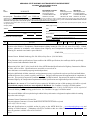
Sealed bids for furnishing the commodities and/or services described below, subject to the Conditions on page 2 of this Bid Invitation will be received at the above-noted mail and
delivery locations until the above-noted bid opening date and time, and then publicly opened at the above-noted bid opening location. Bids must be submitted on this form, with
attachments when appropriate, or bids will be rejected. Late bids and unsigned bids will not be considered.
In compliance with this Bid Invitation and subject to all the Conditions thereof, the undersigned offers and agrees to furnish any and all items upon which prices are quoted, at the price
set opposite each item.
Company Name:
Name (Type or Print):
Address:
Title:
Phone:_________________________Fax:
State:
City:
Zip:
Federal Tax ID or Social Security No.:
E-mail Address:
Signature:
Signature must be legible, original (not photocopied) and in ink.
Unsigned bids will be rejected.
Item
No.
Description
Quantity
Unit
Unit Price
Amount
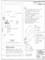
Furnish and Install a 40-Ton Chiller complete with vibration insulators and baffle tank and a new Direct Digital Control
System at the District 1 Headquarters Administration building located at 2701 U.S. 64, west of Jct. Hwy. 1 North,
Wynne, Arkansas in accordance with Arkansas State Highway and Transportation Department Specifications and
Drawing P-1 attached to and made a part of this bid.
LUMP SUM__________________________
Contact Person: Richard Strasburg (501-569-2624) or Ray Gruver (501-569-2090)
If any literature and/or specifications of items conflict with AHTD specifications, the conflict(s) shall be specifically
noted, corrected and submitted with the bid.
Subsection 105.04, 108.07, 109.01 and 109.02 of the AHTD Standard Specifications for Highway Construction, Edition
of 1996, will be in effect. (Specifications are accessible on our web site at
www.ahtd.state.ar.us/contract/progcon/general/stdspecs.htm.)
Bid price shall include all labor, materials, and equipment necessary to perform the work as specified, and shall further
include all licenses, fees, permits, royalties, and all taxes. Bid price shall represent full compensation for completion of
the work. This provision supersedes Condition 4 on Page 2 of Bid Invitation. Payment will be made in accordance with
Arkansas Highway & Transportation Department Standard Specifications and Applicable Special Provisions.
Bid Bond in the amount of 5% of total bid price required of all bidders at time of bid opening or bid will be rejected.
Personal and company checks are not acceptable as Bid Bonds. See Condition 3 on page 2 of Bid Invitation.
Performance Bond only (no checks of any kind allowed) in the amount of 100% of total bid price will be required of
successful bidder prior to providing goods/services. See Condition 3 on page 2 of Bid Invitation.
The successful bidder will be required to begin within 10 days after notice to begin and complete within 60 working
days after notice to begin
Arkansas General Contractor’s License No. _____________________.
Current Arkansas Contractor’s License Number must be listed or bid will be rejected
(A.C.A. ¶17-25-101 et.seq.).
Bids and Specifications are available on-line by going to the AHTD Web Site – www.arkansashighways.com and
clicking on “Bids/Contracts”. Tabulations will also be available at this site within 72 hours after bid opening. If you
have any questions, call this office at 501-569-2667.
42-81
ARKANSAS STATE HIGHWAY AND TRANSPORTATION DEPARTMENT
Page 2
STANDARD BID CONDITIONS
M-08-043P
1.
ACCEPTANCE AND REJECTION: The Arkansas State Highway and Transportation Department (AHTD) reserves the right to reject any or all bids, to
accept bids in whole or in part (unless otherwise indicated by bidder), to waive any informalities in bids received, to accept bids on materials or equipment
with variations from specifications where efficiency of operation will not be impaired, and to award bids to best serve the interest of the State.
2.
PRICES: Unless otherwise stated in the Bid Invitation, the following will apply: (1) unit prices shall be bid, (2) prices should be stated in units of quantity
specified (feet, each, lbs., etc.), (3) prices must be F.O.B. destination specified in bid, (4) prices must be firm and not subject to escalation, (5) bid must be
firm for acceptance for 30 days from bid opening date. In case of errors in extension, unit prices shall govern. Discounts from bid price will not be
considered in making awards.
3.
BID BONDS AND PERFORMANCE BONDS: If required, a Bid Bond in the form of a cashier’s check, certified check, or surety bond issued by a surety
company, in an amount stated in the Bid Invitation, must accompany bid. Personal and company checks are not acceptable as Bid Bonds. Failure to
submit a Bid Bond as required will cause a bid to be rejected. The Bid Bond will be forfeited as liquidated damages if the successful bidder fails to provide
a required Performance Bond within the period stipulated by AHTD or fails to honor their bid. Cashier’s checks and certified checks submitted as Bid Bonds
will be returned to unsuccessful bidders; surety bonds will be retained. The successful bidder will be required to furnish a Performance Bond in an amount
stated in the Bid Invitation and in the form of a cashier’s check, certified check, or surety bond issued by a surety company, unless otherwise stated in the
Bid Invitation, as a guarantee of delivery of goods/services in accordance with the specifications and within the time established in the bid. Personal and
company checks are not acceptable as Performance Bonds. In some cases, a cashier’s check or certified check submitted as a Bid Bond will be held
as the Performance Bond of the successful bidder. Cashier’s checks or certified checks submitted as Performance Bonds will be refunded shortly after
payment has been made to the successful bidder for completion of all terms of the bid; surety bonds will be retained. Surety bonds must be issued by a
surety company authorized to do business in Arkansas, and must be signed by a Resident Local Agent licensed by the Arkansas State Insurance
Commissioner to represent that surety company. Resident Agent’s Power-of-Attorney must accompany the surety bond. Certain bids involving labor will
require Performance Bonds in the form of surety bonds only (no checks of any kind allowed). In such cases, the company issuing the surety bond must
comply with all stipulations herein and must be named in the U. S. Treasury listing of companies holding Certificates of Authority as acceptable sureties on
Federal Bonds and as acceptable reinsuring companies. Any excess between the face amount of the bond and the underwriting limitation of the bonding
company shall be protected by reinsurance provided by an acceptable reinsuring company. Annual Bid and Performance Bonds on file with E & P Division
must have sufficient unencumbered funds to meet current bonding requirements, or the bid will be rejected, unless the balance is submitted as set forth
above, prior to bid opening.
TAXES: The AHTD is not exempt from Arkansas State Sales and Use Taxes, or local option city/county sales taxes, when applicable, and bidders are
responsible to the State Revenue Department for such taxes. These taxes should not be included in bid prices, but where required by law, will be paid by
the AHTD as an addition thereto, and should be added to the billing to the AHTD. The AHTD is exempt from Federal Excise Taxes on all commodities
except motor fuels; and excise taxes should not be included in bid prices except for motor fuels. Where applicable, tax exemption certificates will be
furnished by the AHTD.
4.
5.
“ALL OR NONE” BIDS: Bidders who wish to bid “All or None” on two or more items shall so stipulate on the face of bid sheet; otherwise, bid may be
awarded on an individual item basis.
6.
SPECIFICATIONS: Complete specifications should be attached for any substitution or alternate offered, or where amplification is necessary. Bidder’s
name must be placed on all attachments to the bid.
7.
EXCEPTIONS TO SPECIFICATIONS: Any exceptions to the bid specifications must be stated in the bid. Any exceptions to manufacturer’s published
literature must be stated in the bid, or it will be assumed that bidder is bidding exactly as stated in the literature.
8.
BRAND NAME REFERENCES: All brand name references in bid specifications refer to that commodity or its equivalent, unless otherwise stated in Bid
Invitation. Bidder should state brand or trade name of item being bid, if such name exists.
9.
FREIGHT: All freight charges should be included in bid price. Any change in common carrier rates authorized by the Interstate Commerce Commission will
be adjusted if such change occurs after the bid opening date. Receipted common carrier bills that reflect ICC authorized rate changes must be furnished.
10. SAMPLES, LITERATURE, DEMONSTRATIONS: Samples and technical literature must be provided free of any charge within 14 days of AHTD request,
and free demonstrations within 30 days, unless AHTD extends time. Failure to provide as requested within this period may cause bid to be rejected.
Samples, literature and demonstrations must be substantially the same as the item(s) being bid, unless otherwise agreed to by AHTD. Samples that are
not destroyed will be returned upon request at bidders expense. Samples from successful bidders may be retained for comparison with items actually
furnished.
11. GUARANTY: Unless otherwise indicated in Bid Invitation, it is understood and agreed that any item offered or shipped on this bid shall be newly
manufactured, latest model and design, and in first class condition; and that all containers shall be new, suitable for storage or shipment and in compliance
with all applicable laws relating to construction, packaging, labeling and registration.
12. BACKORDERS OR DELAY IN DELIVERY: Backorders or failure to deliver within the time required may constitute default. Vendor must give written
notice to the AHTD, as soon as possible, of the reason for any delay and the expected delivery date. The AHTD has the right to extend delivery if reasons
appear valid. If reason or delivery date is not acceptable, vendor is in default.
13. DEFAULT: All commodities furnished will be subject to inspection and acceptance by AHTD after delivery. Default in promised delivery or failure to meet
specifications authorizes the AHTD to cancel award or any portion of same, to reasonably purchase commodities or services elsewhere and to charge full
increase, if any, in cost and handling to defaulting vendor. Applicable bonds may be forfeited.
14. ETHICS: “It shall be a breach of ethical standards for a person to be retained, or to retain a person, to solicit or secure a State contract upon an agreement
of understanding for a commission, percentage, brokerage, or contingent fee, except for retention of bona fide employees or bona fide established
commercial selling agencies maintained by the contractor for the purpose of securing business.” (Arkansas Code, Annotated, Section 19-11-708).
ARKANSAS STATE HIGHWAY AND TRANSPORTATION DEPARTMENT
SPECIFICATIONS
JOB 11-41
CHILLER REPLACE AND DIRECT DIGITAL CONTROL SYSTEM
FOR
DISTRICT 1 HEADQUARTERS ADMINISTRATION BUILDING
WYNNE, ARKANSAS
SCOPE
Work under this item shall consist of 40 Ton Chiller replacement complete with vibration insulators
and baffle tank and new Direct Digital Control System for the District 1 Headquarters
Administration Building located at 2701 U.S. Highway 64, west of Jct. Highway 1 North, Wynne,
Arkansas. All work for the complete Chiller replacement and Direct Digital Controls shall be as
indicated on the Plans, as called for in these Specifications, or as directed by the Engineer. These
Specifications and the Plans cover the furnishing of all materials, labor, tools, equipment,
machinery, caulking, drayage, rigging, fees, permits, and any and all incidental items required to
complete the work.
LOCAL CONDITIONS
Bidders are required to visit the site prior to submission of proposal to familiarize themselves with
local conditions, including general characteristics of the existing structures and contents and
accessibility of the work.
PERMITS
The Contractor, if awarded the Contract for the Chiller replacement and Direct Digital Controls,
shall obtain and also pay for all permits required, shall give all legal notices, and shall pay for all
fees and taxes required for the work.
EXAMINATION OF PLANS AND SPECIFICATIONS
The Contractor shall examine the Plans and Specifications and shall become fully informed as to
the extent and character of the work to be performed. No consideration will be given to alleged
misunderstanding of materials to be furnished or work to be required under this Contract.
Submission of a proposal is an implied consent to the conditions of these Specifications and of the
Plans.
PROTECTION OF EXISTING FACILITY
The Contractor is advised that the work is to be performed in and on an existing building which is
occupied. The Contractor shall exercise care and caution to prevent interference with those
working in this facility. The Contractor is also advised that he is responsible for protecting the
existing facilities and occupants against damage or injury from his workmen, work in progress, or
the elements.
Page 2 of 35
SCHEDULING AND COMPLETION OF WORK
The Contractor shall schedule his work so as to create a minimum amount of inconvenience to the
normal work routine of the District Personnel.
All work for the chiller shall be completed so as the installation and/or connections will take as little
time as possible. The District Engineer shall be notified a minimum of 24 hours before any
heating/cooling is taken out of service.
ACCESS TO THE WORK
The Engineer or his representatives shall have access to the work at all times and shall be
permitted to approach, enter or examine all stages or phases of the work as it progresses, and
shall have authority to reject work which is defective in workmanship or material.
REQUIRED SUPERVISION
The Contractor shall keep on the job at all times, when work is in progress, a competent
superintendent satisfactory to the Engineer. The superintendent shall represent the Contractor in
his absence and all instructions given to him shall be binding on the Contractor. Workmanship
shall be by craftsmen skilled in their trade and shall be in accordance with the best standard
practice.
ACCIDENT PREVENTION
Precaution shall be exercised at all times for the protection of persons and property. The safety
provisions of applicable laws, building and construction codes shall be observed. Machinery,
equipment and other hazards shall be guarded in accordance with safety provisions of the Manual
of Accident Prevention in Construction, published by the Associated General Contractors of
America, to the extent that such provisions are not in contravention of applicable laws. The
Contractor shall be responsible for any damage which may be caused by workmen during the
performance of the work.
CONTRACT TIME LIMIT
The Contractor shall begin within ten (10) days after notice to begin and shall complete the work
within sixty (60) working days after notice to begin.
QUALITY OF MATERIAL
All material, appliances or appurtenances furnished under these Specifications shall be new,
unused, and shall be free from defects and imperfections.
Any material, appliance or
appurtenance found to be defective shall be replaced by the Contractor at no additional cost to the
Arkansas Highway and Transportation Department, for material or labor. All material shall comply
with the Arkansas State Highway and Transportation Department Standard Specifications for
Highway Construction, Edition of 2003 and these Specifications. Any material not covered in the
above Specifications or on the Plans shall be approved by the Engineer.
Page 3 of 35
SUBSTITUTION OF MATERIAL
It is intended that the Contractor have the option of substituting a material or appliance that will
perform the function equally as well as the one named. The Engineer shall be given written notice
two (2) weeks prior to the proposed use of a substitution so that a decision can be made as to the
equal merits of the two (2) products. No substituted items shall be installed until written approval is
received by the Contractor.
CLEAN-UP
The Contractor shall not allow any waste material or rubbish caused by his employees to
accumulate in or about the premises but shall promptly remove same. At completion of the work,
all rubbish, tools, scaffolding and surplus materials shall be removed and the Contractor shall leave
the site clean and ready to use.
WARRANTY
Entire project to be warranted for (1) one year on labor and materials and five (5) years on the
chiller compressors.
CLIMATE CONTROL SYSTEM – MATERIALS AND CONSTRUCTION METHODS
GENERAL
This work shall include: removal of chiller, and related items as required; furnishing and installation
of new 40-ton air cooled chiller, complete with vibration insulators and baffle tank; extension
chilled water piping with metal cased insulation as required to valves; antifreeze chilled water
systems to -30°F; extension of electrical service to chiller including switchgear phase protection,
thermometers, pressure gauges, conduit, wire and devices; installation of zone controls; all cleanup; and furnishing all materials, labor, tools, machinery, hardware, fasteners, caulk, paint and any
and all incidental items for the chiller replacement, complete, in place and operating.
CHILLER
Remove existing chiller from roof and related items. Furnish and install a new roof mounted Chiller,
baffle tank and related items as indicated and scheduled on the Plans, including building structural
members and vibration isolation as required for Chiller roof support.
PIPING
A. CHILLED AND CITY WATER PIPING - All chilled water piping and city water piping shall be
Type "L" hard-drawn copper with wrought copper fittings and sil-fos solder.
B. EXPANSION - All piping connections shall be made to allow for expansion and contraction with
swing joints or expansion loops required.
C. CONDENSATE AND DRAIN PIPING - All condensate and drain piping shall be Type "M" harddrawn copper with wrought copper fittings and sil-fos solder.
Page 4 of 35
D. PIPE HANGERS - All piping shall be supported from the building structure by approved
hangers to maintain the required grade, prevent vibration, and provide for expansion and
contraction. Hanger spacing shall not exceed ten (10') feet. Install saddles on all insulated
piping.
E. AIR VENTS - Air vents shall be placed at all high points in the systems with drains at low
points. Run piping so as to avoid air pockets.
F. Flexible Connectors shall be provided on each side of chiller and shall be US Flex, BMHN, 250
psi, 350 degree with bronze braid, annular or helical construction, or approved equal. Piping
shall be supported independently of connectors.
G. THERMOMETERS - Thermometers shall be Trerice Econ-O-Therm #4352, 6-1/2" case length,
red appearing mercury tube, stainless steel frame front, separable brass socket, range of 30
degree F. to 240 degree F., or approved equal.
H. GAUGES - Gauges shall be Marshalltown Catalog #43, range of 0 to 300' of water, or approved
equal.
EQUIPMENT SUPPORTS
The new chiller shall be supported by an approved system attached to the existing roof structure,
designed for the equipment to be furnished with vibration isolation pads designed to prevent the
transmission of equipment vibration to the building structure.
PAINTING
All conduit, piping, etc., shall be painted following the same color code in the existing facility.
ELECTRICAL INSTALLATION
A. GENERAL CONDITIONS - All portions of these Specifications which apply or could apply to the
Electrical portion of the Specifications are made a part of this Section.
B. SWITCHGEAR – If necessary new disconnect switches, breakers, contacts, controls and wiring
shall be installed, of a size and type as required. The existing panelboard shall be modified if
necessary. Provide properly sized heaters for all motor activating devices.
Page 5 of 35
C. WIRE AND CONDUIT - All wiring shall be Code Type THHN, copper of the sizes indicated on
the Plans. No wire smaller than #12 AWG shall be used.
No conduit smaller than 3/4" shall be used. All steel conduit shall be galvanized inside and
outside and shall be Electronite, or approved equal, and shall include all necessary fittings,
connectors, hangers, etc., required for a complete installation. The conduit system shall be
electrically continuous for grounding purposes. For motor connections in exterior or damp
locations, use polyvinylchloride (PVC) jacketed flexible conduit.
D. GROUNDING - All equipment shall be permanently and effectively grounded in accordance
with the National Electrical Code.
DIRECT DIGITAL CONTROL SYSTEM
GENERAL
This system shall provide the Direct Digital Control (DDC), Energy Management and Building
Automation System (BAS) for the air conditioning, heating and ventilating systems and shall
interface with other microprocessor based building subsystems as shown on the drawings and as
specified.
INSTRUCTIONS
The system specified in this document shall be WebCTRL®, manufactured by Automated Logic
Corporation. Alternate systems are acceptable providing they comply with the native BACnet
architecture, web browser access described in this specification and the attached I/O Points
Schedule
SCOPE OF WORK
A. CONTRACTOR'S RESPONSIBILITIES – The Contractor shall furnish and install all necessary
software and hardware, wiring, pneumatic tubing, and computing equipment in compliance with
this specification. Any variances from this specification or related documentation shall be
submitted in writing at the time of bid.
B. System Requirements:
1. Standard Material/Products – All material and equipment used shall be standard
components, regularly manufactured and available, and not custom designed especially for
this project
2. Modular Design – The system architecture shall be fully modular permitting expansion of
application software, system peripherals, and field hardware.
3. Performance – The system, upon completion of the installation and prior to acceptance of
the project, shall perform all operating functions as detailed in this specification.
Page 6 of 35
C. Equipment:
1. System Hardware – The Contractor shall provide the following:
a. PC’s, PDA’s, server(s), routers, modems and control modules as specified.
b. All sensing devices, relays, switches, indicating devices, and transducers required to
perform the functions as listed in I/O Summary Tables.
c. All monitoring and control wiring and air tubing.
2. System Software – The Controls Contractor shall provide all software identified in Part 2 of
this specification, including the BAS Server, fully configured database, graphics, reports,
alarm/events. The Graphical User Interface (GUI) shall be completely Web based as
specified herein.
D. INPUT/OUTPUT POINT SUMMARY SCHEDULE – The system as specified shall monitor,
control, and calculate all of the points and perform all the functions as listed in I/O Point
Summary Schedule.
E. CODES AND REGULATIONS:
1. Standards Authority – All electrical equipment and material, and its installation, shall
conform to the current requirements of the following authorities:
a. Occupational Safety and Health Act (OSHA)
b. National Electric Code (NEC)
c. National Fire Code
d. Uniform Mechanical Code
e. Uniform Building Code
f. Uniform Plumbing Code
2. Product Applicable Standards. All distributed, standalone and unitary controllers supplied
shall be in compliance with the following listings and standards:
a. UL916 for Open Energy Management (for U.S. and Canada)
b. FCC Part 15, Sub-Part B, Class A
c. CE Electro Magnetic Compatibility
d. <UUKL Optional: Only for Smoke Evacuation and where specified elsewhere>
3. Manufacturer’s Quality System – The control system manufacturer shall be ISO9001 listed
for design and manufacture of environmental control systems for precise control and
comfort, indoor air quality, HVAC plant operation, energy savings and preventative
maintenance. ISO Certification shall be by a registrar that is accredited by an internationally
recognized organization such as BSI (British Standards Institute). Copy of ISO9001
certificate shall be submitted with bid.
4. Conflict of Codes – Where two or more codes conflict, the most restrictive shall apply.
Nothing in this specification or related documentation shall be construed to permit work not
conforming to applicable codes.
Page 7 of 35
GENERAL CONDITIONS
A. CHANGES IN SCOPE OF WORK – Any changes in the scope of work must be authorized by a
written Change Order, and issued by the Department, in accordance with Contract conditions.
B. Correction of Work
1. Contractor’s Responsibility – The Contractor shall promptly correct all work the Department
finds defective or failing to conform to the Contract Documents. The Contractor shall bear all
cost of correcting such work.
2. During Warranty – If, within the warranty period required by the Contract Documents, any of
the work is found to be defective or not in accordance with the Contract Documents, the
Contractor shall correct it promptly after receipt of a written notice from the Department to
do so. The Department shall give notice promptly after discovery of the condition.
C. Coordination of Work During Construction
The Contractor shall coordinate any necessary changes in work scheduling with the
Department to minimize disruption.
1. The Contractor shall protect the installed works by other trades.
2. The Contractor shall coordinate with other trades.
3. The Contractor shall repair any damage caused by his work to building(s) and equipment at
no additional cost to the owner.
D. Warranty
The Contractor shall warrant, from the date of final acceptance by the department , that all
systems, subsystems, component parts, and software are fully free from defective design,
materials, and workmanship for a period of one year or longer as indicated in this specification.
SUBMITTALS, DOCUMENTATION, ACCEPTANCE AND TRAINING
A. Submittals:
1. Shop Drawings – A minimum of six (6) copies of Shop Drawings shall be submitted and
shall consist of a complete list of equipment, materials, manufacturer's technical literature,
cut-sheets, and installation instructions. Drawings shall contain proposed layout, complete
wiring, routing, schematic diagrams, tag number of devices, software descriptions,
calculations, installation details, and any other details required to demonstrate that the
system will function properly.
2. Drawing Approval – Shop Drawings shall be approved before any equipment is installed.
Controls contractor shall allow a minimum of five (5) days for drawing approval.
Page 8 of 35
3. As-Built Drawings – All drawings shall be reviewed after the final system checkout and
updated or corrected to provide "As-Built" Drawings to show exact installation. All Shop
Drawings will be acknowledged in writing by the Department before installation is started
and again after the final checkout of the system. The system will not be considered
complete until the "As-Built" Drawings have received their final approval. The Contractor
shall deliver three (3) sets of "As-Built" Drawings.
B. Documentation:
Operating and Maintenance (O&M) manuals for the system shall be made available
electronically and include the following categories: Workstation User's Manual, Project
Engineering Handbook, and Software Documentation.
1. BAS User's Manual shall contain as a minimum:
a.
b.
c.
d.
e.
f.
g.
h.
i.
j.
System overview
Networking concepts
Launching a web browser from a networked PC and login
Web Browser Graphical User Interface (GUI) screen menus and their definitions
Creating, modifying or deleting schedules
Uploading and downloading software to the field hardware
Creating historical trends, collecting trend data and generating trend graphs
Enabling and assigning alarms and messages to reporting actions/groups
Report generation and ‘third party software’
Backing up software and data files
2. Project Engineering Manual for Direct Digital Control shall contain as a minimum:
a. System architecture overview and networking configuration
b. Hardware cut-sheets and product descriptions
c. The Contractor shall deliver three (3) sets of "As-Built" Drawings. All drawings shall be
reviewed after the final system checkout and updated to provide "As-Built" drawings.
The system will not be considered complete until the "As-Built" drawings have received
their final approval.
d. Installation, mounting and connection details for all field hardware and accessories
e. Commissioning, setup and backup procedures for all control modules/accessories, BAS
server software, and database.
f. Listing of basic terminology, alarms/messages, error messages and frequently used
commands or shortcuts.
3. BAS Software Documentation shall contain as a minimum:
a. The Contractor shall provide all Graphical Programs, detailing their application to specific
HVAC equipment and electrical/mechanical subsystems, together with a glossary or icon
symbol library detailing the function of each graphical icon. Revisions made as a result of
the submittal process, during the installation, start-up or acceptance portion of the
project, shall be accurately reflected in the "As-Builts".
b. Graphical representation of the mechanical equipment hierarchy for the project including
all equipment controlled by the BAS. For example: a VAV terminal box may be the
Page 9 of 35
source for increased cooling demand and require the primary VAV AHU to operate
which, in turn, requires the chillers to operate.
c. Detailed listing of all alarm and event messages programmed for designated
mechanical/electrical equipment and required operator action.
C. Acceptance Test:
1. Acceptance Testing – Upon completion of the installation, the Contractor shall start up the
system and perform all necessary calibration, testing, and debugging operations. The
Contractor in the presence of the Owner’s representative shall perform an acceptance test.
2. Notice of Completion – When the system performance is deemed satisfactory, the system
parts will be accepted for beneficial use and placed under warranty. At this time, the
Department shall issue a "notice of completion" and the warranty period shall start.
D. System Training
System Use Instructions – Controls Contractor shall provide full Computer Based Training
(CBT) in addition to training of designated personnel in the operation, maintenance, and
programming of the system.
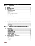
BAS SERVER & WEB BROWSER GUI
The BAS contractor shall provide system software based on a server/thin-client architecture,
designed around the open standards of web technology. The BAS server shall communicate using
ASHRAE’s BACnet/IP protocol, and in addition, offer concurrent support over the same data-link of
the following protocols: LonWorks, MODBUS, and SNMP. Server shall be accessed using a web
browser over the Department intranet and remotely over the Internet.
The intent of the thin-client architecture is to provide the operator(s) complete access to the BAS
system via a web browser. The thin-client web browser Graphical User Interface (GUI) shall be
browser and operating system agnostic, meaning it will support Microsoft and Netscape Navigator
browsers (5.5 or later versions), and Windows as well as non-Window operating systems. No
special software, (active-x components or fat java clients) shall be required to be installed on the
PC’s / PDA’s used to access the BAS via a web browser.
The BAS server software must support at least the following server platforms (Windows NT, Sun
Solaris and Linux). The BAS server software shall be developed and tested by the manufacturer of
the system standalone controllers and network controllers/routers. Third party manufactured and
developed BAS software is not acceptable.
The web browser GUI shall provide a completely interactive user interface and must offer the
following features as a minimum:
•
•
•
•
•
Trending
Scheduling
Downloading Memory to field devices
Real time 'live' Graphic Programs
Tree Navigation
Page 10 of 35
•
•
•
•
•
Parameter change of properties
Setpoint Adjustments
Alarm / Event information
Configuration of operators
Execution of global commands
A. SOFTWARE COMPONENTS – All software components of the BAS system software shall be
installed and completed in accordance with the specification. BAS system components shall
include:
1. Server Software, Database and Web Browser Graphical User Interface
2. System Configuration Utilities for future modifications to the system
3. Graphical Programming Tools
4. Direct Digital Control software
5. Application Software
B. BAS SERVER DATABASE – The BAS server software shall utilize a Java DataBase
Connectivity (JDBC) compatible database such as: MS Access, MS SQL 8.0, Oracle 8i or IBM
DB2. BAS systems written to non standard and/or proprietary databases are not acceptable.
C. DATABASE OPEN CONNECTIVITY – The BAS server database shall be Java DataBase
Connectivity (JDBC) compatible, allowing real time access of data via the following standard
mechanisms:
1. Open protocol standard like CORBA or SOAP
2. OLE/OPC (for Microsoft Client’s/Server platform only)
3. Import/Export of the database from or to XML (eXtensible Mark-up Language)
D. COMMUNICATION PROTOCOL(S) – The native protocol for the BAS server software shall be
BACnet over Ethernet DataLink as defined by ASHRAE standard SPC135. The BAS Server
shall support BACnet/IP Annex J to enable communication through common routers.
Proprietary protocols over TCP/IP are not acceptable. In addition, the software shall be able to
support concurrent operation of multiple standard and non-standard protocols such as:
1. Automated Logic’s Legacy Protocol
2. SMNP
3. LonWorks over IP*
IMPORTANT NOTE: LonMark or LonWorks devices must be networked from LonTalk to an
Ethernet Datalink and IP data structure, using a LonTalk to IP Router like an i1000 Echelon
Router. Binding of all LON devices including Domain, Subnet, Node ID, and the SNVT’s
structure, in addition to configuration of all network variables for IP tunneling shall be the
Page 11 of 35
responsibility of the LON device supplier. ALL I/O points listed in the I/O Point Summary shall
be configured through the i1000 LON/IP router(s). A copy of Echelon’s proprietary LNS
Services and LON Manager shall be supplied at no cost to the Department by the supplier of
the LON devices.
E. CROSS PLATFORM CAPABILITY – The BAS system software (client and server) shall be
operating system and hardware agnostic, being able to run on Windows 2000, Windows NT,
Windows XP, Sun Microsystems Solaris and Red Hat Linux.
F. Thin Client – Web Browser Based
(The GUI shall be thin client or browser based and shall meet the following criteria):
1. Web Browser’s for PC’s – Only a 5.5 or later browser (Explorer/Navigator) will be required
as the GUI, and a valid connection to the server network. No installation of any custom
software shall be required on the operator’s GUI workstation/client. Connection shall be
over an intranet or the Internet. A firewall shall be installed (as necessary) to protect the
Department Intranet.
2. Secure Socket Layers – Communication between the Web Browser GUI and BAS server
shall offer encryption using 128-bit encryption technology within Secure Socket Layers
(SSL). Communication protocol shall be Hyper-Text Transfer Protocol (HTTP).
3. PDA’s – BAS Server software must support other browsers used by Personal Digital
Assistants like 3Com Palm Pilots and other Internet appliances specified herein.
WEB BROWSER GRAPHICAL USER INTERFACE
A. WEB BROWSER NAVIGATION – The Thin Client web browser GUI shall provide a
comprehensive user interface. Using a collection of web pages, it shall be constructed to "feel"
like a single application, and provide a complete and intuitive mouse/menu driven operator
interface. It shall be possible to navigate through the system using a web browser to
accomplish B thru J of this section. The Web Browser GUI shall (as a minimum) provide a
Navigation Pane for navigation, and a Action Pane for display of animated graphics, schedules,
alarms/events, live graphic programs, active graphic setpoint controls, configuration menus for
operator access, reports, and reporting actions for events.
B. LOGIN – On launching the web browser and selecting the appropriate domain name or IP
address, the operator shall be presented with a login page that will require a login name and
password. Navigation in the system shall be dependent on the operator’s role privileges, and
geographic area of responsibility (see J of this section).
Page 12 of 35
C. NAVIGATION PANE – The Navigation Pane shall comprise a Navigation Tree which defines a
geographic hierarchy of the Department's BAS system. Navigation through the GUI shall be
accomplished by clicking on appropriate level of a navigation tree (consisting of expandable
and collapsible tree control like Microsoft’s Explorer program), and/or by selecting dynamic links
to other system graphics. Both the navigation tree and action pane defined in D of this section
shall be displayed simultaneously, enabling the operator to select a specific system or
equipment, and view the corresponding graphic. The navigation tree shall as a minimum
provide the following views: Geographic, Network, Groups and Configuration.
1. Geographic View shall display a logical geographic hierarchy of the system including: cities,
sites, buildings, building systems, floors, equipment and BACnet objects.
2. Network View shall display the hierarchy of the actual BACnet IP Intranet network. This can
include: Systems, Site, Networks, Routers, Half-Routers, Devices, Equipment and all the
BACnet Objects in a device.
3. Groups View shall display Scheduled Groups and custom reports.
4. Configuration View shall display all the configuration categories (Operators, Schedule,
Event, Reporting and Roles).
5. The navigation tree shall have a view selector to enable/disable various types of tree
ornaments, like a clock to indicate where schedules have been assigned in the building.
D. ACTION PANE – The Action Pane shall provide several functional views for each HVAC or
mechanical/electrical subsystem specified. A functional view shall be accessed by clicking on
the corresponding button:
1. Graphics – Using animated gifs or other graphical format suitable for display in a web
browser, graphics shall include aerial building/campus views, color building floor-plans,
equipment drawings, active graphic setpoint controls, web content, and other valid HTML
elements. The data on each graphic page shall automatically refresh at a rate defined by
the operator.
2. Properties – Shall include graphic controls and text for the following: Locking or overriding
BACnet objects, demand strategies, and any other valid data required for setup. Changes
made to the properties pages shall require the operator to depress a ‘accept/cancel’ button.
3. Schedules – Shall be used to create, modify/edit and view schedules based on the systems
geographical hierarchy (using the navigation tree) and in compliance with G of this section.
4. Events – Shall be used to view alarm event information geographically (using the navigation
tree), acknowledge events, sort events by category, actions and verify reporting actions.
5. Trends – Shall be used to display associated trend and historical data, modify colors, date
range, axis and scaling
Page 13 of 35
6. Logic – Live Graphic Programs: Shall be used to display a ‘live’ graphic programs of the
control algorithm for the mechanical/electrical system selected in the navigation tree.
Other actions such as Print, Help, Command, and Logout shall be available via a drop-down
window.
E. COLOR GRAPHICS – The Web Browser GUI shall make extensive use of color in the graphic
pane to communicate information related to setpoints and comfort. Animated .gif’s or .jpg,
active setpoint graphic controls shall be used to enhance usability. Graphics tools used to
create Web Browser graphics shall be non-proprietary and conform to the following basic
criteria:
1. Display Size – The GUI workstation software shall graphically display in 1024 by 768 pixels
24 bit True Color.
2. General Graphic – General area maps shall show locations of controlled buildings in relation
to local landmarks.
3. Color Floor Plans – Floor plan graphics shall show heating and cooling zones throughout
the buildings in a range of colors, which provide a visual display of temperature relative to
their respective setpoints (see F of this section). The colors shall be updated dynamically as
a zone's actual comfort condition changes.
4. Mechanical Components – Mechanical system graphics shall show the type of mechanical
system components serving any zone through the use of a pictorial representation of
components. Selected I/O points being controlled or monitored for each piece of equipment
shall be displayed with the appropriate engineering units. Animation shall be used for
rotation or moving mechanical components to enhance usability.
5. Minimum System Color Graphics – Color graphics shall be selected and displayed via a
web browser for the following:
a. Each piece of equipment monitored or controlled including each terminal unit
b. Each building
c. Each floor and zone controlled
F. Zone Setpoint Adjustments
Color floor plans displayed via a web browser shall utilize a contiguous band of colors, each
corresponding to actual zone temperatures relative to the desired heating and cooling
setpoints. The ideal temperature shall be shown as a green color band. Temperatures slightly
warmer than ideal shall be shown in yellow, and even warmer temperature band shall be shown
in orange. Temperatures slightly cooler than ideal shall be light blue, and even cooler
temperatures shall be shown as dark blue. All alarm colors shall be in red.
Active Zone Graphic Setpoint Controls: Utilizing a mouse, it shall be possible to select
occupied or unoccupied setpoints (corresponding to the floor plan colors) and drag the color
slide bar(s) to increase or decrease heating and cooling setpoints. In addition to the slide bars,
an operator may type the numeric value of the heating and cooling setpoints. The floor plan
Page 14 of 35
graphic shall then change colors on a zone-by-zone basis to reflect the actual temperature in
each zone relative to the changed heating or cooling setpoint.
G. Hierarchical Schedules:
Utilizing the Navigation Tree displayed in the web browser GUI, an operator (with password
access) shall be able to define a Normal, Holiday or Override schedule for an individual piece of
equipment or room, or choose to apply a hierarchical schedule to the entire system, site or floor
area. For example, Independence Day 'Holiday' for every level in the system would be created
by clicking at the top of the geographic hierarchy defined in the Navigation Tree. No further
operator intervention would be required and every control module in the system with would be
automatically downloaded with the "Independence Day" Holiday.
All schedules that affect the system/area/equipment highlighted in the Navigation Tree shall be
shown in a summary schedule table and graph.
1. BACnet Schedules – Schedules shall comply with the BACnet standard, (Schedule Object,
Calendar Object, Weekly Schedule property and Exception Schedule property) and shall
allow events to be scheduled based on:
a.
b.
c.
d.
Types of schedule shall be Normal, Holiday or Override
A specific date,
A range of dates,
Any combination of Month of Year (1-12, any), Week of Month (1-5, last, any), Day of
Week (M-Sun, Any)
e. Wildcard (example, allow combinations like second Tuesday of every month).
2. Schedule Categories – The system shall allow operators to define and edit scheduling
categories (different types of "things" to be scheduled; for example, lighting, HVAC
occupancy, etc.). The categories shall include: name, description, icon (to display in the
hierarchy tree when icon option is selected) and type of value to be scheduled.
3. Schedule Groups – In addition to hierarchical scheduling, operators shall be able to define
functional Schedule Groups, comprised of an arbitrary group of areas/rooms/equipment
scattered throughout the facility and site. For example, the operator shall be able to define
an 'individual tenant' group – who may occupy different areas within a building or buildings.
Schedules applied to the 'tenant group' shall automatically be downloaded to control
modules affecting spaces occupied by the 'tenant group'.
4. Intelligent Scheduling – The control system shall be intelligent enough to automatically turn
on any supporting equipment needed to control the environment in an occupied space. If
the operator schedules an individual room in a VAV system for occupancy, for example, the
control logic shall automatically turn on the VAV air handling unit, chiller, boiler, and/or any
other equipment required to maintain the specified comfort and environmental conditions
within the room.
Page 15 of 35
5. Partial Day Exceptions – Schedule events shall be able to accommodate a time range
specified by the operator (ex: board meeting from 6 pm to 9 pm overrides Normal schedule
for conference room).
6. Schedule Summary Graph – The schedule summary graph shall clearly show Normal
versus Holiday versus Override Schedules, and the net operating schedule that results from
all contributing schedules. Note: In case of priority conflict between schedules at the
different geographic hierarchy, the schedule for the more detailed geographic level shall
apply.
7. Schedule Distribution – For reliability and performance, instead of maintaining a single
schedule in a field device that writes over the network to notify other devices when a
scheduled event occurs, field devices will only keep their part of the schedule locally. The
BAS server software shall determine which nodes a hierarchical schedule applies to and will
create/modify the necessary schedule objects in each field device as necessary.
H. EVENTS (& ALARMS) – Events and alarms associated with a specific system, area, or
equipment selected in the Navigation Tree, shall be displayed in the Action Pane by selecting
an "Events" view. Events, alarms, and reporting actions shall have the following capabilities:
1. Events View – Each event shall display an Event Category (using a different icon for each
event category), date/time of occurrence, current status, event report, and a bold URL link
to the associated graphic for the selected system, area or equipment. The URL link shall
indicate the system location, address and other pertinent information. An operator shall
easily be able to sort events, edit event templates and categories, acknowledge or force a
return to normal in the Events View as specified in this section.
2. Event Categories – The operator shall be able to create, edit or delete event categories
such as HVAC, Maintenance, Fire, or Generator. An icon shall be associated with each
Event category, enabling the operator to easily sort through multiple events displayed.
3. BACnet Event Templates – BACnet Event template shall define different types of alarms
and their associated properties. As a minimum, properties shall include a reference name,
verbose description, severity of event, acknowledgement requirements, high/low limit and
out of range information.
4. Event Areas – Event Areas enable a operator to assign specific Event Categories to specific
Event Reporting Actions. For example, it shall be possible for an operator to assign all
HVAC Maintenance events on the 1st floor of a building to email the technician responsible
for maintenance. The Navigation Tree shall be used to setup Event Areas in the Graphic
Pane.
5. Event Time/Date Stamp –All events shall be generated at the DDC control module level and
comprise the Time/Date Stamp using the standalone control module time and date.
Page 16 of 35
6. Event Configuration – Operators shall be able to define the type of events generated per
BACnet object. A ‘network’ view of the Navigation Tree shall expose all BACnet objects and
their respective Event Configuration. Configuration shall include assignment of event, alarm,
type of Acknowledgement and notification for return to normal or fault status.
7. Event Summary Counter – The view of events in the Graphic Pane shall provide a numeric
counter, indicating how many events are active (in alarm), require acknowledgement, and
total number of events in the BAS Server database.
8. Event Auto-Deletion – Events that are acknowledged and closed, shall be auto-deleted from
the database and archived to a text file after an operator defined period.
9. Event Reporting Actions – Event Reporting Actions specified shall be automatically
launched (under certain conditions) after an event is received by the BAS server software.
Operators shall be able to easily define these Reporting Actions using the Navigation Tree
and Graphic Pane through the web browser GUI. Reporting Actions shall be as follows:
a. Print – Alarm/Event information shall be printed to the BAS server’s PC or a networked
printer.
b. Email –Email shall be sent via any POP3-compatible e-mail server (most Internet
Service Providers use POP3). Email messages may be copied to several email
accounts.
NOTE: Email reporting action shall also be used to support alphanumeric paging
services, where email servers support pagers.
c. File Write – The ASCII File write reporting action shall enable the operator to append
operator defined alarm information to any alarm through a text file. The alarm
information that is written to the file shall be completely definable by the operator. The
operator may enter text or attach other data point information (such as AHU discharge
temperature and fan condition upon a high room temperature alarm).
d. Write Property –The write property reporting action updates a property value in a
hardware module.
e. SNMP – The Simple Network Management Protocol (SNMP) reporting action sends an
SNMP trap to a network in response to receiving an event.
f. Run External Program –The Run External Program reporting action launches specified
program in response to an event.
10. Event Simulator – The web browser GUI user shall provide an Event Simulator to test
assigned Reporting Actions. The operator shall have the option of using current time or
scheduling a specific time to generate the Event. Utilizing the Navigation Tree and dropdown menus in the Graphic Pane, the operator shall be able to select the Event Type,
Status, Notification, Priority, Message, and whether acknowledgement is required.
Page 17 of 35
I. TRENDS – Trends shall conform to the BACnet Trend Log Object specification. Trends shall
both be displayed and user configurable through the Web Browser GUI. Trends shall comprise
analog, digital or calculated points simultaneously. A trend log’s properties shall be editable
using the Navigation Tree and Graphic Pane.
1. Viewing Trends – The operator shall have the ability to view trends by using the Navigation
Tree and selecting a Trends button in the Graphic Pane. The system shall allow y- and xaxis maximum ranges to be specified and shall be able to simultaneously graphically display
multiple trends per graph.
2. Local Trends –Trend data shall be collected locally by Multi-Equipment/Single Equipment
general-purpose controllers, and periodically uploaded to the BAS server if historical
trending is enabled for the BACnet object. Trend data, including run time hours and start
time date shall be retained in non-volatile module memory. Systems that rely on a
gateway/router to run trends are NOT acceptable.
3. Resolution – Sample intervals shall be as small as one second. Each trended point will
have the ability to be trended at a different trend interval. When multiple points are selected
for display that have different trend intervals, the system will automatically scale the axis.
4. Dynamic Update – Trends shall be able to dynamically update at operator-defined intervals.
5. Zoom/Pan – It shall be possible to zoom-in on a particular section of a trend for more
detailed examination and 'pan through' historical data by simply scrolling the mouse.
6. Numeric Value Display – It shall be possible to pick any sample on a trend and have the
numerical value displayed.
7. Copy/Paste – The operator must have the ability to pan through a historical trend and copy
the data viewed to the clipboard using standard keystrokes (i.e. CTRL+C, CTRL+V).
J. SECURITY ACCESS – Systems that Security access from the web browser GUI to BAS server
shall require a Login Name and Password. Access to different areas of the BAS system shall
be defined in terms of Roles, Privileges and geographic area of responsibility as specified:
1. Roles – Roles shall reflect the actual roles of different types of operators. Each role shall
comprise a set of 'easily understood English language' privileges. Roles shall be defined in
terms of View, Edit and Function Privileges.
a. View Privileges shall comprise: Navigation, Network, and Configuration Trees,
Operators, Roles and Privileges, Alarm/Event Template and Reporting Action.
b. Edit Privileges shall comprise: Setpoint, Tuning and Logic, Manual Override, and Point
Assignment Parameters.
Page 18 of 35
c. Function Privileges shall comprise: Alarm/Event Acknowledgement, Control Module
Memory Download, Upload, Schedules, Schedule Groups, Manual Commands, Print,
and Alarm/Event Maintenance.
2. Geographic Assignment of Roles – Roles shall be geographically assigned using a similar
expandable/collapsible navigation tree. For example, it shall be possible to assign two
HVAC Technicians with similar competencies (and the same operator defined HVAC Role)
to different areas of the system.
GRAPHICAL PROGRAMMING
The system software shall include a Graphic Programming Language (GPL) for all DDC control
algorithms resident in standalone control modules. Any system that does not use a drag and drop
method of graphical icon programming as described herein is NOT acceptable. GPL is a method
used to create a sequence of operations by assembling graphic microblocks that represent each of
the commands or functions necessary to complete a control sequence. Microblocks represent
common logical control devices used in conventional control systems, such as relays, switches,
high signal selectors, etc., in addition to the more complex DDC and energy management
strategies such as PID loops and optimum start. Each microblock shall be interactive and contain
the programming necessary to execute the function of the device it represents.
Graphic programming shall be performed while on screen and using a mouse; each microblock
shall be selected from a microblock library and assembled with other microblocks necessary to
complete the specified sequence. Microblocks are then interconnected on screen using graphic
"wires," each forming a logical connection.
Once assembled, each logical grouping of microblocks and their interconnecting wires then forms
a graphic function block which may be used to control any piece of equipment with a similar point
configuration and sequence of operation.
A. GRAPHIC SEQUENCE – The clarity of the graphic sequence must be such that the operator
has the ability to verify that system programming meets the specifications, without having to
learn or interpret a manufacturer's unique programming language. The graphic programming
must be self-documenting and provide the operator with an understandable and exact
representation of each sequence of operation.
B. SIMULATION – Full simulation capability shall be provided with the graphic programming.
Operator shall be able to fully simulate the constructed control sequence prior to downloading
into field control modules. Simulation capabilities shall include step-by-step, accelerated time,
and operator defined simulation criteria like outside weather, demand, and communication
status. Multiple graphic programs shall be simulated and displayed in split screens at the same
time.
C. GPL CAPABILITIES – The following is a minimum definition of the capabilities of the Graphic
Programming software:
Page 19 of 35
1. Function Block (FB) – Shall be a collection of points, microblocks and wires which have
been connected together for the specific purpose of controlling a piece of HVAC equipment
or a single mechanical system.
2. Logical I/O – Input/Output points shall interface with the control modules in order to read
various signals and/or values or to transmit signal or values to controlled devices.
3. BACnet Points – Shall be points that comply with the BACnet structure as defined in the
BIBB’s Addendum B1/B2, and the BACnet standard.
4. Microblocks – Shall be software devices that are represented graphically and may be
connected together to perform a specified sequence. A library of microblocks shall be
submitted with the control contractors bid.
5. Wires – Shall be Graphical elements used to form logical connections between microblocks
and between logical I/O. Different wires types shall be used depending on whether the
signal they conduct is analog or digital.
6. Labels – Labels shall be similar to wires in that they are used to form logical connections
between two points. Labels shall form a connection by reference instead of a visual
connection, i.e. two points labeled 'A' on a drawing are logically connected even though
there is no wire between them.
7. Parameter – A parameter shall be a value that may be tied to the input of a microblock..
8. Properties – Dialog boxes shall appear after a microblock has been inserted which has
editable parameters associated with it. Default parameter dialog boxes shall contain various
editable and non-editable fields and shall contain 'push buttons’ for the purpose of selecting
default parameter settings.
9. Icon – An icon shall be graphic representation of a software program. Each graphic
microblock has an icon associated with it that graphically describes it function.
10. Menu-bar Icon – Shall be an icon that is displayed on the menu bar on the GPL screen,
which represents its associated graphic microblock.
11. Live Graphical Programs – The Graphic Programming software must support a 'live' mode,
where all input/output data, calculated data, and setpoints shall be displayed in a 'live' realtime mode.
For each piece of HVAC equipment, the entire graphic program shall be displayed through
the Web Browser GUI. The operator must have the ability to scroll through the entire 'live'
graphic program as necessary. Piecemeal graphic programs that only show one part of
HVAC equipment program at any one time are NOT acceptable. For example, when viewing
an AHU live graphic program, the operator shall see the entire AHU graphic program, not
just the Heating Coil control.
Page 20 of 35
BAS SERVER HARDWARE
A. COMPUTER CONFIGURATION (HARDWARE INDEPENDENT):
1. Central Server – The BAS Contractor shall provide a server configuration that includes the
following components as a minimum:
2. 1 GHz, PIII or higher CPU (or non-Intel platform equivalent to this) – Dual Processor
3. 256Mb of RAM minimum, 512 MB RAM preferred.
4. 10 gigabyte hard disk, 1.44M 3 ½" floppy drive, SVGA Card with 1024 x 768, 24-bit True
Color, Iomega 100MB Zip Drive or Back-up system of customer’s choice, 24X CD Rom
Drive, 17" SVGA Color Monitor, Keyboard and mouse, 56Kbps EIA-232C Modem with
automatic answer/originate capability
5. Operating system for the computer operator workstation server shall be Microsoft Windows
NT 4.0, 2000, XP or RedHat Linux 6.0 or Sun Solaris 7.0
6. Internet Explorer 6.0 or later
7. 10 Base-T Ethernet Port
8. Printer capable of providing letter quality print (a color printer is preferred).
reporting alarms, a printer capable of handling fanfold paper is desirable.
Note: For
B. STANDARD CLIENT – The thin-client Web Browser BAS GUI shall be Microsoft Internet
Explorer (6.0 or later) running on Microsoft 98, 2000, NT, XP. No special software, (active-x
components or fat java clients) shall be required to be installed on the PC’s / PDA’s used to
access the BAS via a web browser. The following is the minimum suggested hardware
requirements for a Windows/Intel client:
1. 500Mhz, PIII or higher CPU (or non-Intel platform equivalent to this)
2. 128Mb of RAM minimum
3. 6 gigabyte hard disk, 1.44M 3 ½” floppy drive, SVGA Card with 1024 x 768, 24-bit True
Color, 24X CD Rom Drive, 17” SVGA Color Monitor
4. Operating system for the computer operator workstation server shall be Microsoft Windows
98, NT 4.0, 2000, or XP
5. Internet Explorer 5.5 or later
6. Connection to the Intranet/Internet
Page 21 of 35
C. WEB APPLIANCES – The BAS thin client architecture shall take advantage of the browsers
built into web appliances such as:
1. Palm Pilot
2. Compaq iPaq
3. Web Tablets
NETWORK ROUTERS & BRIDGES
The controller network shall use BACnet as its native communication protocol. Network bridges
and routers must be of a modular design to ensure reliability and system performance.
BACNET ROUTER
The central system shall use the building Local Area Network (LAN) for communication. The
communication between the central server and the controllers shall be BACnet/IP. A router
shall be provided, as required, to bridge BACnet/IP and the data link used between the
controllers (BACnet over ARCNET or MS/TP). Proprietary protocols are NOT acceptable.
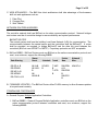
A. BACnet BIBBS – BACnet Routers must use BACnet as the native communication protocol and
must, as a minimum, support the following BIBBS:
Alarm
Device
Network
Data Sharing
Event
Schedule Trend
Man.
Man.
DS-RP-A, B
DS-RPM-B
DS-WP-A, B
DS-WPM-B
DS-COVU-A, B
AE-N-B
AE-ACKB
AEASUM-B
SCHEDB
T-VMTB
T-ATRB
DM-DDBA, B
DM-DOBB
DM-DCCB
NM-RC-A
B. FIRMWARE UPDATES – The BACnet Router utilize FLASH memory to allow firmware updates
to be performed remotely.
STANDALONE CONTROLLERS
A. General Purpose Multiple Application Controllers:
1. BACnet BIBBS – General Purpose Multiple Application controllers must use BACnet as the
native communication protocol between controllers and must, as a minimum, support the
following BIBBS:
Page 22 of 35
Data Sharing
DS-RP-A, B
DS-RPM-B
DS-WP-A, B
DS-WPM-B
DS-COVU-A, B
Alarm
Event
AE-N-B
AE-ACK-B
AE-ASUMB
Schedule
Trend
Device Man.
SCHED-B
T-VMT-B
T-ATR-B
DM-DDB-A,
B
DM-DOB-B
DM-DCC-B
DM-TS-B
DM-UTC-B
DM-RD-B
2. Communication Speed – Controllers shall communicate at a minimum of 156 Kbps using
ARCNET implemented over EIA-485 using a shielded twisted pair at the Data Link Layer.
3. General Specification– Each General Purpose Multiple Application Controller must be
capable of standalone direct digital operation utilizing its own 32 bit processor, non-volatile
flash memory, input/output, 12 bit A to D conversion, hardware clock/calendar and voltage
transient and lightning protection devices. A separate co-processor shall be used for
communications to the controller network. All non-volatile flash memory shall have a battery
backup of at least five years. Firmware revisions to the module shall be made from the BAS
server or remotely over the Intranet or Internet. Controllers that require component changes
to implement firmware revisions are NOT acceptable.
4. Point Expansion – The General Purpose Multiple Application Controllers shall be
expandable to the specified I/O point requirements. Each controller shall accommodate
multiple I/O Expander Modules via a designated expansion I/O bus port. These expander
modules shall expand the total point capacity of each controller up to 192 points where
specified. The controller, in conjunction with the expansion modules, shall act as one
standalone controller.
5. Point Programming – All point data, algorithms and application software within a controller
shall be custom programmable from the operator workstation.
6. Program Execution – Each General Purpose Multiple Application Controller shall execute
application programs, calculations, and commands via a 32-bit microcomputer resident in
the controller. All operating parameters for application programs residing in each controller
shall be stored in read/writ able nonvolatile flash memory within the controller and will be
able to upload/download to/from the BAS Server.
7. Self-Test Diagnostics – Each controller shall include self-test diagnostics, enabling the
controller to report malfunctions to the router and BAS Server.
8. PID Loops – Each General Purpose Multiple Application Controller shall contain both
software and firmware to perform full DDC Proportional, Integral, Derivative (PID) control
loops and programs.
9. Input-Output Processing:
Page 23 of 35
a. Digital Outputs shall be relays, 24 Volts AC or DC maximum, 3 amp maximum current.
Each configured as normally open or normally closed using jumpers and provide dry
contacts. Each output shall have a manual Hand-Off-Auto switch for local override and
an LED to indicate the operating mode. Triac outputs are NOT acceptable.
b. Universal Inputs shall be Thermistor (BAPI Curve II) 10K Ohm at 77°F (25°C), 0-5VDC,
10K Ohm maximum source impedance, 0-20mA - 24 VDC loop power, 250 Ohm input
impedance, dry contact - 0.5mA maximum current.
c. Analog Output shall be electronic, voltage mode 0-10VDC or current mode 4-20mA.
d. Analog Pneumatic Outputs shall be 0-20psi – Each pneumatic output shall have a
feedback transducer to be used in the system for any software programming needs.
The feedback transducer shall measure the actual psi output value and not a calculated
value. Each output shall have a manual override switch that will allow each output to be
configured in one of three ways: open, closed, or automatic operation. An LED shall
indicate the state of each output.
B. General Purpose Single Application Controllers:
1. BACnet BIBBS – The General Purpose Single Application Controllers must use BACnet as
the native communication protocol between controllers and must, as a minimum, support
the following BIBBS:
Alarm
Data Sharing
Event
Schedule
Trend
Device Man.
DS-RP-A, B
DS-RPM-B
DS-WP-A, B
DS-WPM-B
DS-COVU-A, B
AE-N-B
AE-ACK-B
AE-ASUMB
SCHED-B
T-VMT-B
T-ATR-B
DM-DDB-A,
B
DM-DOB-B
DM-DCC-B
DM-TS-B
DM-UTC-B
DM-RD-B
2. Communication Speed – Controllers shall communicate at a minimum of 156 Kbps using
ARCNET implemented over EIA-485 using an unshielded twisted pair at the Data Link
Layer.
3. General Specification – General Purpose Single Application controllers must be capable of
stand-alone DDC operation utilizing its own 32 bit processor, nonvolatile flash memory,
input/output, 8 bit A to D conversion, hardware clock/calendar and voltage transient protection
devices. A separate co-processor shall be used for communications to the controller
network. All RAM memory shall have a battery backup of at least five years. Firmware
revisions to the module shall be made from the BAS server, or remote locations over the
Internet. Controllers that require component changes to implement Firmware revisions are
NOT acceptable.
Page 24 of 35
4. Point Programming – All point data, algorithms, and application software within the
controllers shall be custom programmable from the Operator Workstation.
5. Program Execution – Each General Purpose Single Application Controller shall execute
application programs, calculations, and commands via a 32-bit microcomputer resident in
the controller. All operating parameters for the application program residing in each
controller shall be stored in read/writ able nonvolatile flash memory within the controller and
will be able to upload/download to/from the Operator Workstation.
6. Self-Test Diagnostics – Each controller shall include self-test diagnostics, enabling the
controller to report malfunctions to the router and BAS Server input.
7. PID Loops – Each General Purpose Single Application Controller shall contain both
software and firmware to perform full DDC PID control loops.
8. Rooftop Mounting – The General Purpose Single Application Controllers shall be capable of
being mounted directly in or on rooftop AHU equipment.
9. Operating Temperature – The General Purpose Single Application Controllers shall be
capable of proper operation in an ambient temperature environment of -20°F to +150°F (28.9° to 65.6°C).
10. Input-Output Processing:
a. Digital Outputs shall be relays, 24 Volts AC or DC maximum, 3 amp maximum current.
Each output shall have a manual Hand-Off-Auto switch for local override and an LED to
indicate the operating mode. Triac outputs are NOT acceptable.
b. Universal Inputs shall be Thermistor (BAPI Curve II) 10K Ohm at 77°F (25°C), 0-5VDC 10K Ohm maximum source impedance, 0-20mA - 24 VDC loop power, 250 Ohm input
impedance, Dry Contact - 0.5mA maximum current.
c. Analog Electronic Outputs shall be voltage mode 0-10VDC or current mode 4-20mA.
d. Enhanced Zone Sensor Input shall provide one thermistor input, one local setpoint
adjustment, one timed local override switch, and an occupancy LED indicator.
C. Unitary Controller Network
1. Unitary Controllers:
a. BACnet BIBBS – The Unitary Controllers shall use BACnet as the native
communications protocol between controllers on the unitary controller network and must,
as a minimum support the following BIBBS:
Page 25 of 35
Data
Sharing
Device
Man.
DS-RP-B
DS-WP-B
DM-RD-B
DM-PT-B
b. Communication Speed – The communication between unitary controllers shall be 38.4
Kbps minimum over EIA-485 using an MS/TP architecture.
c. Sensor Support – Each Unitary Controller shall be able to support various types of zone
temperature sensors, such as; temperature sensor only, temperature sensor with built-in
local override switch and temperature sensor with built-in setpoint adjustment switch.
d. Airflow Transducer – In order to provide reliable Pressure Independent VAV operation,
Unitary Controllers for pressure independent VAV applications shall have a precision
built-in Honeywell AWM series airflow transducer for accurate air flow measurement.
e. Integral Actuator – Each Unitary Controller for VAV applications shall have an integral
direct coupled electronic actuator with the following features:
•
•
•
•
•
•
•
•
The actuator shall provide on-off/floating point control with a minimum of 35 in-lb of
torque.
The assembly shall mount directly to the damper operating shaft with a universal VBolt clamp assembly.
The actuator shall not require any limit switches, and shall be electronically protected
against overload.
The actuator shall automatically stop when reaching the damper or actuator end
position.
The gears shall be capable of being manually disengaged with a button on the
assembly cover.
A visual pointer for the position of the actuator.
The assembly shall have an anti-rotational strap supplied with the assembly that will
prevent lateral movement.
5-year warranty from the manufacturer.
f. Visual Status – Each Unitary Controller and Unitary Controller Interface shall have LED
indication for visual status of communication, power, and all outputs.
g. Standalone Algorithm – In the event of a loss of communication, each Unitary Controller
shall control from a standalone algorithm, which maintains the assigned space
temperature until communication with the Unitary Control Router is restored.
h. Input/Output Processing:
•
Digital outputs shall be relays, 24 Volts AC or DC maximum, having a 1 Amp
maximum current. Each relay shall be configured as normally open or normally
closed, and provide a dry contact. Triac outputs are NOT acceptable.
Page 26 of 35
•
Universal inputs shall be Thermistor Precon Type II, dry contacts or 0-5VDC with 010K Ohm input impedance.
•
Enhanced Zone Sensor Input. The input shall provide one thermistor input, one local
setpoint adjustment, one timed local override switch, and an occupancy LED
indicator.
•
Analog output electronic, voltage mode 0-10VDC
2. Unitary Controller Router – A router shall be provided to bridge between the unitary
controller network and the main controller network, as required.
BACnet BIBBS – The Unitary Controllers Routers shall use BACnet as the native
communications protocol between controllers on the unitary controller network and must, as
a minimum support the following BIBBS:
Alarm
Data Sharing
Event
Schedule
Trend
Device Man.
DS-RP-A, B
DS-RPM-B
DS-WP-A, B
DS-WPM-B
DS-COVU-A, B
AE-N-B
AE-ACK-B
AE-ASUMB
SCHED-B
T-VMT-B
T-ATR-B
DM-DDB-A,
B
DM-DOB-B
DM-DCC-B
DM-TS-B
DM-UTC-B
DM-RD-B
LOCAL OPERATOR KEYPAD DISPLAY
A. Local Keypad Display (LOK):
1. General Purpose Controller Plug-in – Keypad and display shall be provided where indicated
in the I/O summary. The LOK shall plug directly into any general purpose/multi application
controller and enable maintenance personnel to access and modify specified building
control parameters in any DDC control panel. The LOK shall be panel mounted [or wall
mounted].
2. Interface – The LOK shall comprise a minimum of four function keys and employ a backlit
display for easy reading in poor lighting conditions. Each function key shall act as a 'hotkey' to menus comprised of control parameters. The display shall utilize
English language descriptors rather than cryptic code and a menu penetration technique to
access data. Clearly marked 'up' and 'down' arrow keys shall be used to move between
point descriptors listed in each menu. The LOK backlit display shall be 4 by 40 characters
or 2 by 16 characters, as specified by location in the I/O Point Summary.
Page 27 of 35
2. Menu Language – The English language menus in the LOK shall be constructed using
industry standard HTML. Access to building control parameters shall be protected by
password entry.
B. LOCAL CONTROL PANEL ACCESS – Where shown on the drawings (or at each control panel
location), the contractor shall provide an Ethernet drop which will allow the operator to have full
use of the Web Browser GUI as specified in "BAS Server & Web Browser GUI" section. BAS
Systems that require a laptop computer with central workstation software and database, in
order to provide local access are NOT acceptable.
BUILDING SYSTEMS INTEGRATION
A. PROTOCOL TRANSLATOR MODULE – The BAS System shall establish a seamless
interconnection with other building, electrical and/or mechanical subsystems as well as other
manufacturers control systems using a Protocol Translator as specified below and related
equipment sections of the specification. These systems shall be controlled, monitored and
graphically programmed with the same Graphical Programming Language (GPL) used for all
other control modules.
1. System Information – All system information specified in the I/O Point Summary and related
documents shall be available to the BAS server.
2. OEM Cooperation – Full cooperation by the Original Equipment Manufacturer (OEM) in this
open protocol effort shall be a requirement for bidding this project. OEM manufacturers
shall bid BACnet. OEM manufacturers that utilize other protocols shall include the cost of a
BTM in their bid. If the OEM manufacturer uses the LonWorks protocol, they shall certify
their devices are LONMARK compliant and comply with the requirements of C.2 of "BAS
Server & Web Browser GUI" section.
3. Necessary Equipment Included Price – If the equipment manufacturer does not have this
capability, they shall contact the authorized representative of the BAS for assistance and
shall include in their equipment price any necessary equipment obtained from the BAS
manufacturer to comply with this section.
4. PTM Specification:
a. The PTM shall be a microprocessor based communication device designed to provide
seamless, two-way translation between two or more standard or non-standard protocols.
b. The PTM shall be available for a variety of Data Link\Physical Layer configurations
including PTP (point-to-point) via EIA-232, MS/TP via EIA-485, ARCNET and Ethernet.
c. In addition to BACnet, the PTM shall also support other protocols including Modbus, JBus and other protocols as specified herein for electrical/mechanical subsystems.
d. The PTM shall have at least three communication ports.
One shall be for
communication between native BACnet controllers residing on the controller network.
The other two ports shall have the ability to be configured for different protocols.
Page 28 of 35
e. The PTM shall provide full custom programmability of the data flowing between the
networks using the same graphical programming as specified herein. The system shall
have the ability to create custom building control strategies using global data between
networks.
FIELD HARDWARE/INSTRUMENTATION
A. Input Devices:
1. Type & Accuracy – Temperature sensors shall be of the type and accuracy indicated for the
application. Sensors shall have an accuracy rating within 1% of the intended use
temperature range.
2. Mixed Air Application – Sensors used for mixed air applications shall be the averaging type
and have an accuracy of +1°F (0.5°C).
3. Outside Air Temperature Sensors – Outside air temperature sensors accuracy shall be
within +1°F (0.5°C) in the range of -52°F to 152°F (-46.6°C to 66.6°C).
4. Room Temperature Sensors – Room temperature sensors shall have an accuracy of
+0.36°F (0.25°C) in the range of 32°F to 96°F (0°C to 35.5°C).
5. Chilled Water and Condenser Water Sensors – Chilled water and condenser water sensors
shall have an accuracy of +0.25°F (0.15°C) in their range of application.
6. Hot Water Temperature Sensors – Hot water temperature sensors shall have an accuracy
of +0.75°F (0.3°C) over the range of their application.
B. Pressure Instruments:
1. Differential Pressure and Pressure Sensors
2. Pressure Switches
3. Flow Switches
4. Watt-hour Transducers
5. Voltage-to-Digital Alarm Relays
6. Humidity Sensors
7. Current Sensing Relays
C. Output Devices:
1. Control Relays
Page 29 of 35
2. Solid State Relays (SSR)
3. Electric Solenoid Operated Pneumatic (EP) Valves
4. Electric to Pneumatic (EP) Transducers
D. Valve and Damper Actuators (MODULATING):
1. Electronic Direct-Coupled – Electronic direct-coupled actuation shall be provided.
2. Actuator Mounting – The actuator shall be direct-coupled over the shaft, enabling it to be
mounted directly to the damper shaft. The fastening clamp assemble shall be of a 'V' bolt
design with associated 'V' shaped toothed cradle attaching to the shaft for maximum
strength and eliminating slippage. Spring return actuators shall have a 'V' clamp assembly
of sufficient size to be directly mounted to an integral jackshaft of up to 1.05 inches when
the damper is constructed in this manner. Single bolt or screw type fasteners are not
acceptable
3. Electronic Overload Sensing – The actuator shall have electronic overload or digital rotation
sensing circuitry to prevent damage to the actuator throughout the entire rotation of the
actuator. Mechanical end switches or magnetic clutch to deactivate the actuator at the end
of rotation are not acceptable.
4. Power Failure/Safety Applications – For power failure/safety applications, an internal
mechanical spring return mechanism shall be built into the actuator housing. Nonmechanical forms of fail-safe operation are not acceptable.
5. Spring Return Actuators – All spring return actuators shall be capable of both clockwise or
counterclockwise spring return operation by simply changing the mounting orientation.
6. Proportional Actuators – Proportional actuators shall accept a 0 to 10VDC or 0 to 20mA
control input and provide a 2 to 10VDC or 4 to 20mA operating range. An actuator capable
of accepting a pulse width modulating control signal and providing full proportional operation
of the damper is acceptable.
7. 24 Volts (AC/DC) actuators – All 24VAC/DC actuators shall operate on Class 2 wiring and
shall not require more than 10VA for AC or more than 8 watts for DC applications.
Actuators operating on 120VAC power shall not require more than 10VA. Actuators
operating on 230VAC shall not require more than 11VA.
8. Non-Spring Return Actuators – All non-spring return actuators shall have an external
manual gear release to allow manual positioning of the damper when the actuator is not
powered. Spring return actuators with more than 60 in-lb torque shall have a manual crank
for this purpose.
8. Modulating Actuators – All modulating actuators shall have an external, built-in switch to
allow reversing direction of rotation.
Page 30 of 35
9. Conduit Fitting & Pre-Wiring – Actuators shall be provided with a conduit fitting and a
minimum 3ft electrical cable, and shall be pre-wired to eliminate the necessity of opening
the actuator housing to make electrical connections.
11. U.L. Listing – Actuators shall be Underwriters Laboratories Standard 873 listed and
Canadian Standards Association Class 4813 02 certified as meeting correct safety
requirements and recognized industry standards.
12. Warranty – Actuators shall be designed for a minimum of 60,000 full stroke cycles at the
actuator's rated torque and shall have a 2-year manufacturer's warranty, starting from the
date of installation. Manufacturer shall be ISO9001 certified.
DDC SOFTWARE
The system shall continuously perform Direct Digital Control (DDC) functions at the local control
module in a stand-alone mode. Using Graphical Programming, the operator shall be able to
design and modify control sequence of operation and all tuning parameters.
A. MINIMUM FUNCTION – Each control module shall perform the following functions:
1. Identify, time/date stamp and report BACnet events
2. Execute all application programs specified
3. Execute DDC algorithms
4. Trend and store data
B. CONTROL FAILURE MODE – In the event of a control module failure, all points under its
control shall be commanded to the failure mode as indicated on the I/O Summary Table. All
DDC software shall reside in the respective control module.
1. Orderly Shutdown – Power failures shall cause the control module to go into an orderly
shutdown with no loss of program memory.
2. Automatic Restart – Upon resumption of power, the control module shall automatically
restart and print out the time and date of the power failure and restoration at the respective
Workstation system.
3. Automatic Restart – The restart program shall automatically restart affected field equipment.
The operator shall be able to define an automatic power up time delay for each piece of
equipment under control.
Page 31 of 35
APPLICATIONS SOFTWARE
All software application algorithms described below MUST reside at the local Multi-Application or
Single-Application Controller level. Systems that rely on a workstation PC, server or router to
perform these functions are NOT acceptable. The following applications software shall be provided
for the purpose of optimizing energy consumption while maintaining occupant comfort:
A. TIME OF DAY SCHEDULING (TOD) – The system shall be capable of the following scheduling
features:
1. Schedule by Type – Scheduling by building, area, zone, groups of zones, individually
controlled equipment and groups of individually controlled equipment. Each schedule shall
provide beginning and ending dates and times (hours: minutes). A weekly repeating
schedule, i.e. between 8:00 a.m. and 5:00 p.m., Monday through Friday shall constitute one
schedule.
2. Schedule in Advance – Dated schedules shall be entered up to 9 (nine) years in advance.
3. Self-Deleting – Schedules shall be self-deleting when effective dates have passed.
4. Leap Year – Leap years shall be adjusted automatically without operator intervention.
B. OPTIMUM START/STOP (OSS)/OPTIMUM ENABLE/DISABLE (OED) – This application
provides software to start and stop equipment on a sliding schedule based on the individual
zone temperature and the heating/cooling capacity in °F/hour of the equipment serving that
zone. The heating/cooling capacity value shall be operator adjustable.
Temperature
compensated peak demand limiting shall remain in effect during morning start up to avoid
setting a demand peak.
C. SOURCE TEMPERATURE OPTIMIZATION (STO) – The system shall automatically perform
source optimization for all air handling units, chillers and boilers in response to the needs of
other downstream pieces of equipment, by increasing or decreasing supply temperature
setpoints, i.e. chilled water, discharge air, etc. using owner defined parameters. In addition to
optimization, the STO capability shall also provide for starting and stopping primary mechanical
equipment based on zone occupancy and/or zone load conditions.
Setpoint Reset – The STO program will allow setpoints for various equipment in the
heating/cooling chain to be reset between an operator defined maximum and a minimum
setpoint based on the actual requirements of the building zones. The actual setpoint shall be
calculated based on the number of heating or cooling requests which are currently being
received from the equipment or zones served. Once every update period, the STO program
surveys the network to see if any piece of equipment requires any additional heating or cooling
from its source. As an example, a VAV air handler is the source of cold air for a number of
VAV boxes. Assume that the STO program for the air handler has the following parameters
established for it by the owner (Optimized setpoint description):
1. Initial setpoint is 60.00,
2. Max. setpoint is 65.00,
Page 32 of 35
3. Min. setpoint is 55.00.
4. Every 2.0 mins, trim by 0.25 and respond by -0.50 but no more than 2.0.
Every two minutes, the STO program will total up all of the requests and calculate a new
setpoint:
New setpoint = prev setpoint + 'trim by' + ('respond by' x no. of req.). Assuming four requests
were received and the previous setpoint was 57.00 degrees, the new setpoint would be:
New setpoint = 57.00 + 0.25 + (-0.50 x 4) = 55.25 Deg F
If (the number of requests received) x (the 'respond by' value) > (the 'but no more than' value),
use the 'but no more than' value inside the parenthesis in the above calculation.
D. DEMAND LIMITING (DL) - TEMPERATURE COMPENSATED – The DL application shall be
programmable for a minimum of six separate time of day KW demand billing rate periods. The
system shall be capable of measuring electrical usage from multiple meters serving one
building and each piece of equipment being controlled on the LAN shall be programmable to
respond to the peak demand information from its respective meter.
1. Sliding Window – The demand control function shall utilize a sliding window method with the
operator being able to establish the kilowatt threshold for a minimum of three adjustable
demand levels. The sliding window interval shall be operator selectable in increments of
one minute, up to 60 minutes. Systems that incorporate rotating shed tables are NOT
acceptable.
2. Setpoints for Defined Demand Level – The operator shall have the capability to set the
individual equipment temperature setpoints for each operator defined demand level.
Equipment shall not be shed if these reset setpoints are not satisfied; rather the setpoint
shall be revised for the different established demand levels. The system shall have failed
meter protection, such that when a KW pulse is not received from the utility within an
operator adjustable time period, an alarm will be generated. The system software will
automatically default to a predetermined fail-safe shed level.
3. Information Archiving – The system shall have the ability to archive demand and usage
information for use at a later time.
System shall permit the operator access to this
information on a current day, month to date and a year to date basis.
E. DAY/NIGHT SETBACK (DNS) – The system shall allow the space temperature to drift down
[up] within a preset [adjustable] unoccupied temperature range. The heating [cooling] shall be
activated upon reaching either end of the DNS range and shall remain activated until the space
temperature returns to the DNS range.
1. Outside & Exhaust Air – The system shall be capable of closing all outside air and exhaust
air dampers during the unoccupied period, except for 100% outside air units.
2. Unoccupied Space Temperature – Unoccupied space temperature shall be monitored by
the DDC temperature sensors located in the individual zones being controlled or within a
representative room.
Page 33 of 35
3. Parameter Changes – Operator shall be able to define, modify or delete the following
parameters:
a. DNS setpoint temperature(s)
b. Temperature band for night heating operation
c. Period when the DNS is to be activated
F. Timed Local Override (TLO) – The system shall have TLO input points that permit the
occupants to request an override of equipment that has been scheduled OFF. The system shall
turn the equipment ON upon receiving a request from the local input device. Local input devices
shall be push button (momentary contact), wind-up timer, or ON/OFF switches as detailed in
the I/O summary.
Equipment On Time – If a push button is used the system operator shall be able to define the
duration of equipment ON time per input pulse and the total maximum ON time permitted. The
input point will cancel override time already entered. If a wind-up timer is used the equipment
will stay in override mode until the timer expires. Year to date, month-to-date and current day
override history shall be maintained for each TLO input point. History data shall be accessible
by the operator at any time and shall be capable of being automatically stored on hard disk
and/or printed on a daily basis.
G. SPACE TEMPERATURE CONTROL (STC) – There shall be two space temperature setpoints,
one for cooling and one for heating, separated by a dead band. Only one of the two setpoints
shall be operative at any time. The cooling setpoint is operative if the actual space temperature
has more recently been equal to or greater than the cooling setpoint. The heating setpoint is
operative if the actual space temperature has more recently been equal to or less than the
heating setpoint. There are two modes of operation for the setpoints, one for the occupied
mode (example: heating = 72°F or 22°C, cooling = 76°F or 24.4°C) and one for the unoccupied
mode (example: heating = 55°F or 12.7°C, cooling = 90°F or 32°C).
1. Schedule – The occupied/unoccupied modes may be scheduled by time, date, or day of
week.
2. Color Code – One of seven colors shall be generated to represent the comfort conditions in
the space, and shall be displayed graphically at the operator station.
a. If the actual space temperature is in the dead band between the heating setpoint and the
cooling setpoint, the color displayed shall be green for the occupied mode, representing
ideal comfort conditions. If in the unoccupied mode, the color displayed shall be gray
representing 'after-hours' conditions.
b. If the space temperature rises above the cooling setpoint, the color shall change to
yellow. Upon further rise beyond the cooling setpoint plus an offset, the color shall
change to orange. Upon further rise beyond the cooling setpoint plus the yellow band
offset, plus the orange band offset, the color shall change to red indicating unacceptable
high temperature conditions. At this point an alarm shall be generated to notify the
operator.
Page 34 of 35
c. When space temperature falls below the heating setpoint, the color shall change to light
blue. Upon further temperature decrease below the heating setpoint minus an offset, the
color shall change to dark blue. Upon further space temperature decrease below the
heating setpoint minus the light blue band offset minus the dark blue band offset the
color shall change to red indicating unacceptable low temperature conditions. At this
point an alarm shall be generated to notify the operator.
3. Operator Definable – All setpoints and offsets shall be operator definable. When in the
occupied mode, start-up mode, or when heating or cooling during the night setback
unoccupied mode, a request shall be sent over the network to other equipment in the HVAC
chain, such as to an AHU fan that serves the space, to run for ventilation. The operator
shall be able to disable this request function if desired.
4. Additional Cooling – When comfort conditions are warmer than ideal, indicated by the colors
yellow, orange, and high temperature red, a request for additional cooling shall be sent over
the network to other cooling equipment in the HVAC chain, such as a chiller. This
information is to be used for optimization of equipment in the HVAC chain. The operator
shall be able to disable this function if desired.
5. Additional Heating – When comfort conditions are cooler than ideal; indicated by the colors
light blue, dark blue, and low temperature red; a request for additional heating shall be sent
over the network to other heating equipment in the HVAC chain, such as a boiler. This
information is to be used for optimization of equipment in the HVAC chain. The operator
shall be able to disable this function if desired.
6. Cooling/Heating Setpoints – The cooling [and heating] setpoints may be increased
[decreased] under demand control conditions to reduce the cooling (heating) load on the
building during the demand control period. Up to three levels of demand control strategy
shall be provided. The operator may predefine the amount of setpoint increase [decrease]
for each of the three levels. Each space temperature sensor in the building may be
programmed independently.
7. Optimum Start – An optimum start-up program transitions from the unoccupied setpoints to
the occupied setpoints. The optimum start-up algorithm considers the rate of space
temperature rise for heating and the rate of space temperature fall for cooling under nominal
outside temperature conditions; it also considers the outside temperature; and the heat loss
and gain coefficients of the space envelope (AI: Space Temperature).
8. PID Loop – A PID control loop, comparing the actual space temperature to its setpoint, shall
modulate the dampers [and heating coil valve or heating stages in sequence] to achieve the
setpoint target.
METHOD OF MEASUREMENT
40 Ton Chiller and Direct Digital Control complete, in place and operating, as called for in these
Specifications, as indicated on the Plans, or as directed by the Engineer and accepted, will be
measured for payment by the "Lump Sum".
Page 35 of 35
BASIS OF PAYMENT
Work completed and accepted under this item and measured as provided above, will be paid for at
the lump sum price bid for "40 Ton Chiller and Direct Digital Control System", which price shall be
full compensation for all materials, labor, tools, equipment, machinery, caulking, drayage, rigging,
fees, permits, clean-up, guarantees and any and all incidental items required to complete the work.
PAY ITEM
PAY UNIT
40 Ton Chiller and Direct Digital Control System
Lump Sum