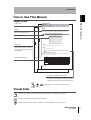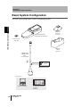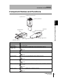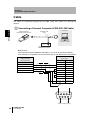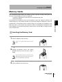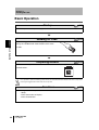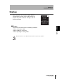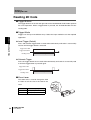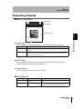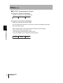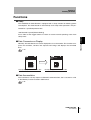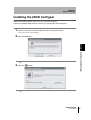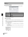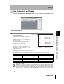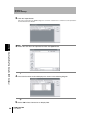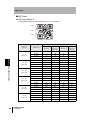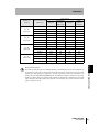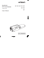
1
Handheld
2D Code Reader
V400-H101/201
User's Manual
Cat. No.
Z222-E1-01
Introduction
Thank you for purchasing the OMRON V400-H101/H201.
This manual describes the functions, performance, and application
methods of the V400-H101/H201.
This manual is intended for personnel with knowledge of electrical
systems. Be sure to read and understand this manual thoroughly before
using the product, and keep this manual in an easily accessible location
for quick reference when required.
Section 1 Product Overview
Section 2 Installation and Connections
Section 3 Reading 2D Code
Section 4 System Settings
Section 5 Troubleshooting
Appendices Specifications and Dimensions
Handheld 2D Code Reader
User's Manual
V400-H101/201
Introduction Section
ÇÕǹÇ?Ç
ëÊ 1 èÕ1 Section
ëÊ 2 èÕ2 Section
ëÊ 3 èÕ3 Section
ëÊ 4 èÕ4 Section 5 Appendices
Introduction Application Considerations (Read and understand this information first.)
Introduction
Introduction
READ AND UNDERSTAND THIS DOCUMENT
Please read and understand this document before using the products. Please consult your OMRON
representative if you have any questions or comments.
WARRANTY
OMRON’s exclusive warranty is that the products are free from defects in materials and workmanship for
a period of one year (or other period if specified) from date of sale by OMRON.
OMRON MAKES NO WARRANTY OR REPRESENTATION, EXPRESS OR IMPLIED, REGARDING
NON-INFRINGEMENT, MERCHANTABILITY, OR FITNESS FOR PARTICULAR PURPOSE OF THE
PRODUCTS. ANY BUYER OR USER ACKNOWLEDGES THAT THE BUYER OR USER ALONE HAS
DETERMINED THAT THE PRODUCTS WILL SUITABLY MEET THE REQUIREMENTS OF THEIR
INTENDED USE. OMRON DISCLAIMS ALL OTHER WARRANTIES, EXPRESS OR IMPLIED.
LIMITATIONS OF LIABILITY
OMRON SHALL NOT BE RESPONSIBLE FOR SPECIAL, INDIRECT, OR CONSEQUENTIAL
DAMAGES, LOSS OF PROFITS OR COMMERCIAL LOSS IN ANY WAY CONNECTED WITH THE
PRODUCTS, WHETHER SUCH CLAIM IS BASED ON CONTRACT, WARRANTY, NEGLIGENCE, OR
STRICT LIABILITY.
In no event shall responsibility of OMRON for any act exceed the individual price of the product on which
liability is asserted.
IN NO EVENT SHALL OMRON BE RESPONSIBLE FOR WARRANTY, REPAIR, OR OTHER CLAIMS
REGARDING THE PRODUCTS UNLESS OMRON’S ANALYSIS CONFIRMS THAT THE PRODUCTS
WERE PROPERLY HANDLED, STORED, INSTALLED, AND MAINTAINED AND NOT SUBJECT TO
CONTAMINATION, ABUSE, MISUSE, OR INAPPROPRIATE MODIFICATION OR REPAIR.
SUITABILITY FOR USE
THE PRODUCTS CONTAINED IN THIS DOCUMENT ARE NOT SAFETY RATED. THEY ARE NOT
DESIGNED OR RATED FOR ENSURING SAFETY OF PERSONS, AND SHOULD NOT BE RELIED
UPON AS A SAFETY COMPONENT OR PROTECTIVE DEVICE FOR SUCH PURPOSES. Please refer
to separate catalogs for OMRON's safety rated products.
OMRON shall not be responsible for conformity with any standards, codes, or regulations that apply to
the combination of products in the customer’s application or use of the product.
At the customer’s request, OMRON will provide applicable third party certification documents identifying
ratings and limitations of use that apply to the products. This information by itself is not sufficient for a
complete determination of the suitability of the products in combination with the end product, machine,
system, or other application or use.
The following are some examples of applications for which particular attention must be given. This is not
intended to be an exhaustive list of all possible uses of the products, nor is it intended to imply that the
uses listed may be suitable for the products:
• Outdoor use, uses involving potential chemical contamination or electrical interference, or conditions or
uses not described in this document.
2
V400-H101/H201
User’s Manual
Introduction
Introduction
• Nuclear energy control systems, combustion systems, railroad systems, aviation systems, medical
equipment, amusement machines, vehicles, safety equipment, and installations subject to separate
industry or government regulations.
• Systems, machines, and equipment that could present a risk to life or property.
Please know and observe all prohibitions of use applicable to the products.
NEVER USE THE PRODUCTS FOR AN APPLICATION INVOLVING SERIOUS RISK TO LIFE OR
PROPERTY WITHOUT ENSURING THAT THE SYSTEM AS A WHOLE HAS BEEN DESIGNED TO
ADDRESS THE RISKS, AND THAT THE OMRON PRODUCT IS PROPERLY RATED AND INSTALLED
FOR THE INTENDED USE WITHIN THE OVERALL EQUIPMENT OR SYSTEM.
PERFORMANCE DATA
Performance data given in this document is provided as a guide for the user in determining suitability and
does not constitute a warranty. It may represent the result of OMRON’s test conditions, and the users
must correlate it to actual application requirements. Actual performance is subject to the OMRON
Warranty and Limitations of Liability.
CHANGE IN SPECIFICATIONS
Product specifications and accessories may be changed at any time based on improvements and other
reasons.
It is our practice to change model numbers when published ratings or features are changed, or when
significant construction changes are made. However, some specifications of the product may be
changed without any notice. When in doubt, special model numbers may be assigned to fix or establish
key specifications for your application on your request. Please consult with your OMRON representative
at any time to confirm actual specifications of purchased products.
DIMENSIONS AND WEIGHTS
Dimensions and weights are nominal and are not to be used for manufacturing purposes, even when
tolerances are shown.
ERRORS AND OMISSIONS
The information in this document has been carefully checked and is believed to be accurate; however, no
responsibility is assumed for clerical, typographical, or proofreading errors, or omissions.
PROGRAMMABLE PRODUCTS
OMRON shall not be responsible for the user’s programming of a programmable product, or any
consequence thereof.
COPYRIGHT AND COPY PERMISSION
This document shall not be copied for sales or promotions without permission.
This document is protected by copyright and is intended solely for use in conjunction with the product.
Please notify us before copying or reproducing this document in any manner, for any other purpose. If
copying or transmitting this document to another, please copy or transmit it in its entirety.
V400-H101/H201
User’s Manual
3
Introduction
Introduction
Meanings of Signal Words
In this manual, precautions are indicated using the following symbols and signal words to ensure safe
use of the V400-H101/H201. The precautions indicated by these symbols and signal words are
important for safety and must be observed.
Indicates a potentially hazardous situation which, if not avoided, will
WARNING result in minor or moderate injury, or may result in serious injury or death.
Additionally there may be significant property damage.
Meanings of Alert Symbols
Indicates the possibility of explosion under specific conditions.
Indicates general prohibitions for which there is no specific symbol.
Alert Statements in this Manual
● WARNINGS
WARNING
This product is not designed or rated for ensuring safety of persons and cannot be
used in safety applications designed to either directly or indirectly detect persons.
Do not use it for such purposes.
A lithium battery is built into the Controller and may occasionally combust, explode,
or burn if not treated properly, which may occasionally result in serious injury.
Dispose of the Controller as industrial waste, and never disassemble, apply
pressure that would deform, heat to 100°C or higher, or incinerate the Controller.
4
V400-H101/H201
User’s Manual
Introduction
Introduction
Regulations and Standards
The V400-H101/H201 complies with the international regulations and standards listed below.
EC Directives
EMC Directive:No.89/336/EEC
EN Standards
(European Standards)
EN61326: 1997, +A1: 1998 +A2: 2001 (EMI: Class A)
Power line: 10 m max. Signal line: 30 m max.
Precautions for Safe Use
Observe the following precautions to ensure safe use of the product.
■ Installation Environment Precautions
• Do not use the product in environments with flammable or explosive gases.
• Do not install outdoors.
■ Power Supply and Wiring Precautions
• Use the product with the power supply voltages specified in this manual.
• Use the cables specified in this manual.
• Keep the power supply cable as short as possible (10 m maximum).
• Use a DC power supply with countermeasures against high-voltage spikes (safe extra
low-voltage circuits on the secondary side).
p.26
■ Other Precautions
• Do not attempt to disassemble, repair, or modify the product. Doing so may cause
product failure or a fire.
• If the product becomes extremely hot, or abnormal odors or smoke occurs, stop using
the product immediately, turn OFF the power, and consult with your OMRON representative.
• Dispose of the product as industrial waste.
• Do not apply pressure or deform the product when disposing of it.
V400-H101/H201
User’s Manual
5
Introduction
Introduction
Precautions for Correct Use
Always observe the following precautions to prevent operation failures, malfunctions, and
adverse effects on performance and equipment.
■ Operating Environment
Do not install the product in the following locations:
• Locations subject to ambient temperature that exceeds the rated temperature range
• Locations subject to rapid changes in temperature (causing condensation)
• Locations subject to relative humidity that exceeds the rated humidity range
• Locations subject to corrosive or flammable gases
• Locations subject to dust, salt, or metallic powder
• Locations subject to direct vibration or shock outside the specified ranges
• Locations subject to direct sunlight
• Locations subject to oil or chemical spray
■ Installation and Handling of Components
• Use the cables specified in this manual.
p.18
■ Connecting and Removing Cables
• Do not connect a cable to the Handheld 2D Code Reader if the other end of the cable
is connected to a personal computer or a Programmable Controller.
• To prevent damage from static electricity, use a wrist strap or another device for preventing electrostatic charges when touching terminals or signal lines inside connectors.
■ Memory Cards
• Do not remove the Memory Card when the Memory Card indicator is lit. Doing so may
result in damage to the Memory Card or the Handheld 2D Code Reader.
• OMRON shall not be responsible in any way for damage or loss of Memory Card data
as a result of mishandling.
p.29
■ Turning OFF the Power Supply
• Do not turn OFF the power supply while a message is being displayed indicating that
processing is being performed. Data in memory will be destroyed, and the product
may not operate correctly the next time it is started.
6
V400-H101/H201
User’s Manual
Introduction
Introduction How to Use This Manual
How to Use This Manual
Page Format
Section Title
Section 4
System Settings
Creating Setting Files Using the 2DCR Configear
Section 4
System Settings
Outline
Create the data setting file for loading setting data to the Handheld 2D Code Reader.
Make the settings for the communications conditions, functions, and display conversion.
Move to the Setting Screen.
▲
Select Setting Reader - Create Setting Data from the menu.
The following window for creating the setting data file will be displayed.
Screen display
Section 4 Creating Setting Files Using the 2DCR Configear
Provides the section number
and subject matter. Can be
used to immediately open the
desired page.
Section 4 Uploading from the Memory Card
Index label
■ Open
Opens the previously created data setting file for editing.
■ Save
Saves the created data setting file.
To save data to the Memory Card, create a folder with the name SETTINGS, and save. The Handheld 2D Code Reader's setting mode cannot start if the data is saved in a folder of a different name.
Communications Settings
The settings shown in the following table are set in the Communications Settings Tab
Page in the Create Setting Data Window.
Setting item
Settings
Baud Rate
Describes the settings.
Parity
Data Length
Stop Bit
Header/Footer
Prefix
Suffix
FCS
9600*, 19,200, or 38,400
None*, odd, or even
7 bits or 8 bits*
1 bit* or 2 bits
None*, 02 <STX> or 1B <ESC>
03 <ETX>, 0A <LF>, 0D<CR>*, or 0D0A <CR+LF>
ON or OFF*
The asterisks indicate default settings.
46
48
V400-H101/201
User’s Manual
V400-H101/201
User’s Manual
Procedure and additional explanations
Information useful during the operation and reference pages are provided here with special marks
to indicate the kind of information being provided.
*This page does not actually exist in this manual.
Visual Aids
Indicates points that are important in using product functions or in application procedures.
Indicates page numbers providing related information.
Indicates helpful information when a problem occurs and explanations of technical terms.
V400-H101/H201
User’s Manual
7
Introduction
Introduction Internet Information
8
Internet Information
Information on the Handheld 2D Code Reader is available on the Internet.
Contact the OMRON representative nearest you regarding the website address.
V400-H101/H201
User’s Manual
Introduction
Introduction
Table of Contents
2
Application Considerations (Read and understand this information first.)
2
Meanings of Signal Words
4
Regulations and Standards
5
Precautions for Safe Use
5
Precautions for Correct Use
6
How to Use This Manual
7
Visual Aids
7
Internet Information
8
Table of Contents
9
Section 1 Product Overview
Table of Contents
Introduction
11
Features
12
Operation Overview
15
Section 2 Installation and Connections
17
Basic System Configuration
18
Component Names and Functions
19
Cable
20
Power Supply
26
Contactor (Optional)
27
Stand (Optional)
28
Memory Cards
29
V400-H101/201
User’s Manual
9
Preface
Preface
Table of Contents
Section 3 Reading 2D Code
31
Basic Operation
32
Startup
33
Reading 2D Code
34
Outputting Results
35
Functions
37
Section 4 System Settings
Overview
40
Installing the 2DCR Configear
41
Communications Using the 2DCR Configear
43
Creating Setting Files Using the 2DCR Configear
46
Uploading from the Memory Card
52
Section 5 Troubleshooting
Troubleshooting
Appendices
55
56
57
Maintenance
58
Specifications and Dimensions
59
ASCII Table
64
FCS Calculation Method
65
Data Capacity Tables
67
Revision History
10
39
V400-H101/201
User’s Manual
70
This section provides an introduction to the Handheld 2D Code Reader's features, functions, basic configuration, and operation flow.
Features
12
Operation Overview
15
V400-H101/201
User’s Manual
Section 1 Product Overview
Section 1
Product Overview
11
Section 1
Product Overview
Features
Section 1 Features
The 2D Code Reader is designed to read two-dimensional code. A built-in monitor and zoom
lens are ideal for reading directly marked 2D code. A Memory Card Slot is also provided along
with a range of useful functions.
Readable Codes
12
Readable codes
DataMatrix
QR Code
Readable sizes
(symbol size)
• ECC200
10 × 10 to 64 × 64
8 × 18 to 16 × 48
Model 1 or 2
21 × 21 to 57 × 57
(Version 1 to Version 10)
V400-H101/201
User’s Manual
Section 1
Product Overview
Zoom Lens (Manual)
The zoom lever can be used to change the
Section 1 Features
field of view, enabling a variety of applications with a single Unit. Two lens variations
provide wide-angle and telescopic views,
covering all viewing needs from paper level
to complicated code.
Dual System Lighting
Coaxial lighting and oblique lighting are provided in a single Unit. The type of the
lighting is automatically selected.
• V400-H101 RGB 3 color coaxial, red
oblique lighting
• V400-H201 Red coaxial, red oblique lighting
Workpieces with different optical characteristics can be read with a single Unit, and
workpieces with a range of direct markings can also be read.
Liquid Crystal Display
The Handheld 2D Code Reader is equipped
with a 1.8-inch Liquid Crystal Monitor,
enabling you to view an image of positioning
OK
SD
ABCDEFGHIJKLMNOPQRST
while reading.
The Handheld 2D Code Reader enables
confirmation of read data and images, previously not possible with handheld readers.
V400-H101/201
User’s Manual
13
Section 1
Product Overview
Memory Card Slot
A Memory Card slot is provided to back up settings on Memory Cards and upload data
Section 1 Features
from Memory Cards. A function is also provided for saving 2D code data that was read
as files in the Memory Card.
p.29
Memory Card
Useful Functions
■ Data Conversion on Display
This function converts data that is read and displays it as a separate text string.
p.49
■ Data Accumulation
This function writes data that is read to the Memory Card.
p.48
14
V400-H101/201
User’s Manual
Section 1
Product Overview
Operation Overview
Section 2 p.17
Prepare the required components and connect them.
Main Peripheral Devices
• Cable
• Power supply device
• Contactor
• Stand
Reading 2D Code
Section 1 Operation Overview
Installation and Connections
Section 3 p.31
Turn ON the power and press the trigger buttons to
read the code.
• Reading method
• Field of view setting
• Display details
System Settings
Section 4 p.39
Basic settings for the Handheld 2D Code Reader
are not required, but settings must be changed
using the Special Tool 2DCR Configear under
the following circumstances.
• To change the communication conditions (See note.)
• To use various functions
These settings can be changed in the Handheld
2D Code Reader using a Memory Card or the communications functions of the 2DCR
Configear.
Note: The default settings are as follows:
Baud rate: 9, 600 bps; Parity: None; Data length: 8 bits; Stop bits: 1 bit
V400-H101/201
User’s Manual
15
Section 1
Product Overview
MEMO
Section 1 Operation Overview
16
V400-H101/201
User’s Manual
Section 2
Installation and Connections
other installation procedures and connections.
Basic System Configuration
18
Component Names and Functions
19
Cable
20
Power Supply
26
Contactor (Optional)
27
Stand (Optional)
28
Memory Cards
29
V400-H101/201
User’s Manual
Section 2 Installation and Connections
This section describes the methods used to connect cables and perform
17
Section 2
Installation and Connections
Basic System Configuration
The basic system configuration is shown in the following diagram.
K
C
LO
Section 2 Basic System Configuration
V400-H101/H201
Handheld 2D Code Reader
Memory Card
(SD card)
V400-AS1
Stand
(optional)
5VDC
V400-W20-2M
V400-W21-2M
Cable
(recommended)
Power supply
device
Recommended product:
OMRON S82K-00705
Host Devices
Personal computer
18
V400-AC1
Contactor
(optional)
V400-H101/201
User’s Manual
Programmable Controller:
CJ Series
CS Series
Section 2
Installation and Connections
Component Names and Functions
(8) Memory Card indicator
(4) Zoom lever
(1) Memory Card slot
Section 2 Component Names and Functions
(2) Image plane
(5) Monitor
(6) Power indicator
(7) Buzzer
(3) Right trigger button
(3) Left trigger button
(9) Cable connector
Name
(1) Memory Card slot
Details
Slot for inserting Memory Card.
(2) Image plane
Camera image plane
(3) Trigger buttons
(Right, Left)
Cancels sleep state for a trigger input or when setting mode is entered.
p.34
(4) Zoom lever
Changes the field of view.
(5) Monitor
Displays the read image/results, and other data.
p.35
(6) Power indicator
Lit when power is first turned ON and remains lit during operation.
p.35
(7) Buzzer
A high- or low-tone buzzer sounds depending on the operation.
p.33
(8) Memory Card indicator Lit while the Memory Card is being accessed. (Do not remove the Memory Card if the
indicator is lit.)
p.35
(9) Cable connector
Connects to a V400-W20-2M or V400-W21-2M Cable.
p.22
V400-H101/201
User’s Manual
19
Section 2
Installation and Connections
Cable
The Cables are specifically designed for the V400. Using other Cables may damage the
devices.
Connecting a Personal Computer (V400-W21-2M Cable)
Section 2 Cable
V400-H101/H201
Handheld 2D Code Reader
Host device
V400-W21-2M
Cable
Personal computer
Power supply
device
5VDC
Recommended product:
OMRON S82K-00705
● Connector
The connector used for V400-W21-2M Cable is a D-sub, 9-pin connector (female).
The connector is compatible with the connection port on the IBM PC/AT or compatible.
Special round connector on
V400-H101/H201
2D Code Reader
IBM PC/AT or compatible
D-sub, 9-pin
Pin No.
Name
Name
1
-
SD
2
RD
RD
3
SD
SG
4
ER
+5 V
5
SG
6
DR
7
RS
8
CS
9
-
Connector cover
Shield wire
0V
+5 V
5
1
9
6
(View of mating section)
20
V400-H101/201
User’s Manual
Section 2
Installation and Connections
Connecting a Programmable Controller (V400-W202M Cable)
Host device
V400-W20-2M
Cable
V400-H101/H201
Handheld 2D Code Reader
Power supply
device
Recommended product:
OMRON S82K-00705
Section 2 Cable
Programmable Controller:
CJ Series
CS Series
● Connector
The connector used for V400-W20-2M Cable is a D-sub, 9-pin connector (male).
The connector is compatible with the connection port on OMRON CJ-series and CSseries Programmable Controller.
Special round connector on
V400-H101/H201
2D Code Reader
Programmable Controller
D-sub, 9-pin
Pin No.
Name
Name
1
-
SD
2
SD
RD
3
RD
SG
4
RS
+5 V
5
CS
6
-
7
-
8
-
9
SG
Connector cover
Shield wire
0V
+5 V
1
5
6
9
(View of mating section)
V400-H101/201
User’s Manual
21
Section 2
Installation and Connections
Connecting Cables to the Handheld 2D Code Reader
Connect one end of the cable to a personal computer or Programmable Controller before connecting
the other end of the cable to the Handheld 2D Code Reader.
Section 2 Cable
1. Attach the provided ferrite cores to the cable.
Attach the ferrite cores in two locations; one at the Handheld 2D Code Reader end of the cable, and the other
at the host device end of the cable.
Close the ferrite cores until a click is heard. Separate from the power lines.
Ferrite cores
2. Connect the cable.
Grasp the cable plug (part A). Line up the alignment mark
on the plug with the alignment mark on the Handheld 2D
Code Reader connector and push the plug in straight.
Cable port
Cable
Plug
D
C
A
22
V400-H101/201
User’s Manual
D
Alignment marks
C
Section 2
Installation and Connections
Use a force of no more than 15 to 20 N to plug in the connector. Pull gently on the cable (approximately 10 N) to make sure the connector is securely connected. After the connector is plugged in,
do not apply a force of more than 30 N to the connector in the following directions. Excessive force
will damage the connector.
30 N
Section 2 Cable
30 N
30 N
3. Place the cable in the groove provided for it in
the case.
4. Close the cover.
Keep fingers clear when closing the case to prevent the case closing on them.
V400-H101/201
User’s Manual
23
Section 2
Installation and Connections
Disconnecting the Cable from the Handheld 2D Code
Reader
1. Disconnect the cable connector from the host device.
Section 2 Cable
p.25
2. Open the cover.
Press down on the indentations on both sides of the cover
as you open it.
Do not apply excessive force to the cover.
3. Disconnect the cable.
Grasp the coupling (part B) on the plug and pull the plug
out straight as shown in the diagram below.
Coupling
Cable
B
4. Close the cover.
Keep fingers clear when closing the case to prevent the case closing on them.
24
V400-H101/201
User’s Manual
Section 2
Installation and Connections
Connecting the Cable to the Host Device
1. Connect the cable connector to the RS-232C
interface on the host device, making sure that
the connector is oriented correctly and not
Section 2 Cable
inserted at an angle. Secure the connector
using the screws on both sides of the connector.
Removing the Cable from the Host Device
1. Remove the cable.
Loosen the screws on both sides of the connector and pull
the connector out straight.
Be sure to loosen the screws on both sides of the
connector sufficiently before removing the connector and do not use excessive force.
V400-H101/201
User’s Manual
25
Section 2
Installation and Connections
Power Supply
Power must be supplied to the V400-H101/H201 via the cable. Wire the power supply
independently of other devices. In particular, keep the power supply wired separately from
inductive loads. Use a power supply that meets the following requirements.
Section 2 Power Supply
Power Supply Requirements
Output current
Power supply voltage
1 A min.
5 VDC±10%
Recommended Power Supply
Model
S82K-00705
Use a DC power supply with safe extra-low-voltage circuits to prevent high voltage. If UL recognition is
required for the overall system, use a UL Class II DC power supply.
■ Connection Method
Wire the power supply cables as shown in the following diagram.
Connect the brown wire to the positive (+) side of the power supply and connect the blue wire to the
negative (−) side of the power supply.
26
V400-H101/201
User’s Manual
Section 2
Installation and Connections
Contactor (Optional)
The Contactor functions as a guide for the distance from the image plane to the code to be
read. By making contact with the read code, the read distance can be easily aligned.
Mounting Procedure
Section 2 Contactor (Optional)
1. Align
the grips on the Contactor with the
grooves on the Handheld 2D Code Reader to
mount it.
Mount by clicking the notches of the grips into the
grooves of the Handheld 2D Code Reader.
Removal Procedure
1. Remove the grips of the Contactor from the
grooves on the Handheld 2D Code Reader
pulling in the direction of the arrow shown in
the diagram on the right
Do not use excessive force when removing the
Contactor grips from the grooves.
V400-H101/201
User’s Manual
27
Section 2
Installation and Connections
Stand (Optional)
The Stand is for holding the V400-H101/H201.
Mounting Procedure
Section 2 Stand (Optional)
1. Use two M4 screws to mount the Stand.
Mounting Hole Dimensions
Two, M4 or
4.2-dia. holes
(Unit: mm)
20.0
Placing the Handheld 2D Code Reader on the Stand
1. Place the Handheld 2D Code Reader in
the Stand as shown in the diagram on
the right.
The Stand is designed to be placed on a horizontal surface. Do not mount the Stand to a wall or
other similar surface.
28
V400-H101/201
User’s Manual
Section 2
Installation and Connections
Memory Cards
The Handheld 2D Code Reader uses Memory Cards to upload or backup setting data and
data to be read. SD Memory Cards are supported.
• Conforms to SD Memory Card "Physical Layer Specification 1.01"
• File format: FAT16
upload the data to easily backup the data to the personal computer. SD Memory Cards are
provided with a write prohibit switch to prohibit writing to or formatting of the Memory Card.
When the switch is set to LOCK, data cannot be written to or deleted from the Memory Card,
and the Memory Card cannot be formatted. These functions are possible by setting the switch
to the unlocked state.
Inserting the Memory Card
Section 2 Memory Cards
Save the data to the Memory Card, insert the Memory Card in the personal computer, and
1. Open the Memory Card slot cover.
Lift the cover gently, without using excessive
force.
2. Position
the Memory Card in the correct
direction and insert in the slot until a click is
heard.
Insert the Memory Card in the direction with the
label side facing the same direction as the monitor of the Handheld 2D Code Reader.
3. Close the Memory Card slot cover.
V400-H101/201
User’s Manual
29
Section 2
Installation and Connections
Removing Memory Cards
1. Open the Memory Card slot cover.
Section 2 Memory Cards
Lift the cover gently, without using excessive
force.
2. Make sure that the indicator on the Memory Card slot is not lit.
Do not remove the Memory Card while the indicator is lit. Doing so may damage the Memory Card
and the Handheld 2D Code Reader.
3. Push the Memory Card in gently until a click
is heard.
The Memory Card will eject slightly.
4. Pull out the Memory Card straight.
5. Close the Memory Card slot cover.
30
V400-H101/201
User’s Manual
Section 3
Reading 2D Code
This section provides information required for reading 2D code.
32
Startup
33
Reading 2D Code
34
Outputting Results
35
Functions
37
V400-H101/201
User’s Manual
Section 3 Reading 2D Code
Basic Operation
31
Section 3
Reading 2D Code
Basic Operation
p.33
Startup
Turn ON the power to the power supply device and start the Handheld 2D Code Reader.
Section 3 Basic Operation
p.34
Reading 2D Code
Press the trigger buttons and keep pressed while
moving the Handheld 2D Code Reader close to the
2D code.
Outputting Results
The read data is output to the monitor and RS-232C
p.35
OK
SD
ABCDEFGHIJKLMNOPQRST
communications.
If no operation is performed during a fixed interval, the Handheld 2D Code Reader will enter a sleep state.
Pressing the trigger buttons will release the sleep state.
Functions
The following functions are provided with the Handheld 2D Code Reader.
• Sleep
• Data Conversion on Display
• Data Accumulation
32
V400-H101/201
User’s Manual
p.37
Section 3
Reading 2D Code
Startup
When the power of the power supply device is
turned ON, the screen on the right will be displayed, the power indicator will light, and the
2D Code Reader
V400-H201
SD
Ver,0.963
buzzer will sound.
(C) Copyright
OMRON CORPORATION
2005
All Rights Reserved
2005/01/05 20:00
Section 3 Startup
■ Buzzer
The buzzer will sound under the following conditions.
• When starting the V400
• When reading is successful
• When operating in setting mode
When the buzzer is set to OFF, the buzzer will not sound for any operation.
V400-H101/201
User’s Manual
33
Section 3
Reading 2D Code
Reading 2D Code
■ Trigger Buttons
The trigger buttons on the left and right side of the Handheld 2D Code Reader perform
the same operations. When a trigger button is pressed, the 2D Code Reader will start
reading code.
■ Trigger Mode
Triggers can be input two different ways. Select the input method to suit the required
Section 3 Reading 2D Code
application.
◆ Level Trigger (Default)
Press and hold the trigger button to read code continuously until code is successfully
read or until the trigger button is released.
Trigger button ON
Trigger button OFF
Reading status
Reading
◆ Alternate Trigger
Press the trigger button once to read code continuously until code is successfully read
or until the trigger button is pressed again.
Trigger button ON
Trigger button OFF
Reading
Reading status
■ Zoom Lever
The zoom lever is used to change the field
of vision to suit the size of the code to be
read.
Model
34
Setting range
V400-H101
5 mm (TELE) to 10 mm (WIDE)
V400-H201
15 mm (TELE) to 30 mm (WIDE)
V400-H101/201
User’s Manual
Section 3
Reading 2D Code
Outputting Results
■ Monitor Description
OK
Image area
SD
ABCDEFGHIJKLMNOPQRST
Text display
◆ Image Area
This area indicates whether reading was successful and Memory Card status.
Item
Details
OK
Displayed in green on the top left side of the screen when 2D codes are read successfully.
Memory Card
Displays the SD mark when a Memory Card is inserted.
Displays the SD mark in red when the Memory Card is active to indicate that the
Memory Card is being accessed.
Section 3 Outputting Results
Image display
◆ Text Display
This area displays reading results and data converted by the display conversion
function. Up to 38 characters can be displayed.
◆ Image Display
This area displays images taken by the Camera.
■ LED Indicators
Indicator
Location
Details
Power
On the bottom of the
monitor
Lit when power is turned ON, and remains lit during operation
Memory Card
Beside the Memory Card
slot
Lit when the Memory Card is being accessed. Do not
remove the Memory Card while this indicator is lit.
V400-H101/201
User’s Manual
35
Section 3
Reading 2D Code
■ RS-232C Communications Output
◆ Output for Successful Readings
Read data is output in the following format.
Header
Read data
Footer
◆ Output for Unsuccessful Readings
Nothing is output with the default setting.
An error code output, however, can be set for unsuccessful readings. (See note.)
Section 3 Outputting Results
36
Note: NG output setting
When the NG output is set to ON, the output contents can be changed.
Output contents when NG output is ON:
• The NG mark is displayed on the monitor in red.
• The data ?E000 is sent via RS-232C communications.
Header
V400-H101/201
User’s Manual
?E000
Footer
Section 3
Reading 2D Code
Functions
■ Sleep
The Handheld 2D Code Reader is equipped with a sleep function for reducing power
consumption. The Code Reader is automatically set to sleep when operation is not performed for a specified period of time.
• 30 Seconds Lapsed (Default Setting)
Press either of the trigger buttons to return to resume normal operating status from
■ Data Conversion on Display
Normally, 2D code data that is read is displayed as is on the monitor. This function compares the read data, converts into separate text strings and displays the converted
data.
p.49
OK
DS1300
SD
Example display when function is OFF
OK
Produced January
DS1300
Section 3 Functions
sleep status.
SD
Example display when function is ON
■ Data Accumulation
The read data is not only output via RS-232C communications, but is created as a file
in the Memory Card and saved in CSV format.
p.48
V400-H101/201
User’s Manual
37
Section 3
Reading 2D Code
MEMO
Section 3 Functions
38
V400-H101/201
User’s Manual
Section 4
System Settings
This section describes the methods used to install and set the 2DCR Configear software.
40
Installing the 2DCR Configear
41
Communications Using the 2DCR Configear
43
Creating Setting Files Using the 2DCR Configear
46
Uploading from the Memory Card
52
V400-H101/201
User’s Manual
Section 4 System Settings
Overview
39
Section 4
System Settings
Overview
Installing the Setting Software
p.41
Obtain the 2DCR Configear application software from the Internet and install it on a personal
computer.
Creating the Setting File
p.46
Create the setting file using the 2DCR Configear.
Specify the required settings using the 2DCR
Configear, and create as a file.
Section 4 Overview
The following items can be set.
1. Communications settings
2. Function settings
Uploading Data
Upload the created setting data to the Handheld 2D Code
Reader.
The following two loading methods are available.
• Using the Memory Card
• Using the 2DCR Configear
40
V400-H101/201
User’s Manual
p.52
Section 4
System Settings
Installing the 2DCR Configear
Obtain the 2DCR Configear and install it on a personal computer.
Contact the OMRON representative nearest you regarding the 2DCR Configear.
1. Open the setup.exe file downloaded from the Sensing Web website.
The following window will be displayed.
2. Click the OK Button.
Section 4 Installing the 2DCR Configear
3. Click the
Button.
V400-H101/201
User’s Manual
41
Section 4
System Settings
4. Click the Continue Button.
Setup will start when the Continue Button is clicked.
Section 4 Installing the 2DCR Configear
42
5. Click the OK Button.
V400-H101/201
User’s Manual
Section 4
System Settings
Communications Using the 2DCR Configear
The 2DCR Configear can be used to communicate with the Handheld 2D Code Reader.
Menu
Communication
Setting
Connect Button
Status display
Direct Command Input
Communication Log
Sends the input text string
to the Handheld 2D Code Reader.
Display Form
Selects the communication log display format
as either text format or hexadecimal.
■ Communication Setting
The following items can be set.
Setting item
Settings
Port No.
COM1*
Baud Rate
9,600*, 19,200, or 38,400
None*, odd, or even
7 bits or 8 bits*
1sbit* or 2 bits
Send
None*, 02 <STX>, or 1B <ESC>
Receive None*, 02 <STX>, or 1B <ESC>
Send
03 <ETX>, 0A <LF>, 0D <CR>*, or 0D0A <CR+LF>
Receive 03 <ETX>, 0A <LF>, 0D <CR>* or 0D0A <CR+LF>
Send
ON or OFF*
Receive ON or OFF*
Parity
Data Length
Stop Bit
Header/Footer
Prefix
Suffix
FCS
Same as Send
to COM 9
Section 4 Communications Using the 2DCR Configear
Connects or disconnects
from the port.
Sets the header, footer, and FCS for receiving to the same settings as for
sending.
The default settings are indicated with an asterisk.
Operation is not possible when the port is connected.
V400-H101/201
User’s Manual
43
Section 4
System Settings
■ Menu
◆ File
Save Log...
Saves the data displayed in the communication log as a text file.
Save Environment
Saves the settings made in the communications settings.
End
Ends the 2DCR Configear.
◆ Edit
Section 4 Communications Using the 2DCR Configear
Copy Log
Copies the log displayed in the communication log to the clipboard.
Erase Log
Deletes the log displayed in the communication log.
◆ Setting Reader
Create Data...
Creates the data setting file for loading set data to the Handheld 2D Code Reader.
p.46
Auto Scan
Automatically obtains the conditions required for communicating with the Handheld 2D
Code Reader.
Operation is not possible when the port is connected.
Send Setting
Sends the data setting file from the host to the Handheld 2D Code Reader.
Operation is not possible when the port is disconnected.
Receive Setting
Sends the setting data for the Handheld 2D Code Reader to the host.
Operation is not possible when the port is disconnected.
Set Date, Time
Sends the clock time of the personal computer in which 2DCR Configear is installed to
the Handheld 2D Code Reader.
Operation is not possible when the port is disconnected.
The clock is factory set to Japanese Standard Time.
44
V400-H101/201
User’s Manual
Section 4
System Settings
◆ Help
Version
Displays the software version of the 2DCR Configear installed.
■ Buttons
◆ Connect
Connects or disconnects the port.
■ Display Form
Selects the format for displaying data in the communication log.
Either text display or hexadecimal display can be selected. (Default setting: Text display)
Section 4 Communications Using the 2DCR Configear
■ Direct Command Input
Sends the input text string to the Handheld 2D Code Reader.
Operation is not possible when the port is disconnected.
■ Status Display
◆ On Line/Off Line
Indicates the port status (On Line: Connected; Off Line: Disconnected)
◆ COM1 9600,n,8,1
Displays the current communications conditions.
This is not displayed when the port is disconnected.
◆ 26/1/2005
Displays the current date.
◆ 9:27
Displays the current time.
V400-H101/201
User’s Manual
45
Section 4
System Settings
Creating Setting Files Using the 2DCR Configear
Create the data setting file for loading setting data to the Handheld 2D Code Reader.
Make the settings for the communications conditions, functions, and display conversion.
▲
Select Setting Reader - Create Data... from the menu.
The following window for creating the setting data file will be displayed.
Section 4 Creating Setting Files Using the 2DCR Configear
■ Open
Opens the previously created data setting file for editing.
■ Save
Saves the created data setting file.
To save data to the Memory Card, create a folder with the name SETTINGS, and save. The Handheld 2D Code Reader's setting mode cannot start if the data is saved in a folder of a different name.
Communication Settings
The settings shown in the following table are set in the Communication Settings Tab
Page in the Create Setting Data Window.
Setting item
Settings
Baud Rate
Parity
Data Length
Stop Bit
Header/Footer
Prefix
Suffix
FCS
9600*, 19,200, or 38,400
None*, odd, or even
7 bits or 8 bits*
1 bit* or 2 bits
None*, 02 <STX> or 1B <ESC>
03 <ETX>, 0A <LF>, 0D<CR>*, or 0D0A <CR+LF>
ON or OFF*
The asterisks indicate default settings.
46
V400-H101/201
User’s Manual
Section 4
System Settings
The format when FCS is ON is as follows:
Header (Prefix)
Read data
FCS (2 bytes) Footer (Suffix)
For details on FCS calculation methods, refer to FCS Calculation Method.
p.65
Section 4 Creating Setting Files Using the 2DCR Configear
V400-H101/201
User’s Manual
47
Section 4
System Settings
Function Settings
Make the following settings in the Initialize Tab of the Create Setting Data Window.
Setting item
Settings
Section 4 Creating Setting Files Using the 2DCR Configear
Trigger*
Level
or Alternate
*
ON or OFF
Between 30 sec* and 120 sec
ON or OFF*
OFF* or ON
Trigger Mode
Buzzer
Sleep Shift Time
Output of NG
Data Accumulation
The asterisks indicate default settings.
■ Data Accumulation
Set whether to collect data.
The Memory Card must be inserted in the Handheld 2D Code Reader to use this function.
When this function is ON, read data will be saved in a file with the following name in the
Memory Card's READDATA folder. The READDATA folder will be automatically generated if it does not already exist.
READ****.csv
Note. The digits indicated by **** start at 0000 and increment by 1 for approximately
each 400 kilobytes.
After reading is completed, the data is written to the Memory Card, which will
take several seconds.
When Appending at date is selected, the date and time will be added to the read data.
Example of Saved File
ABC0001,2005/01/27,12:48:30
ABC0003,2005/01/27,12:51:02
ABC0109,2005/01/27,12:59:41
ABC0075,2005/01/27,12:59:47
Data
48
V400-H101/201
User’s Manual
Date
(Y/M/D)
Time
Section 4
System Settings
Data Conversion on Display
Click the Data Conversion on Display Tab in the Create Setting Data Window to convert a CSV file for display.
1. Create the CSV file for the display
Comment row
conversion function.
To use this function, CSV files for display con-
;Data file for displaying production date
**1*** ,
"Manufact Jan."
spreadsheet software or a text editor for the
**2*** ,
"Manufact Feb."
personal computer.
**3*** ,
"Manufact Mar."
**4*** ,
"Manufact Apr."
**5*** ,
"Manufact May"
ELSE ,
"Warning:Improper"
version must be created using separate
The following formatting restrictions apply.
•
•
•
•
•
File: CSV format (comma delimited)
Maximum No. of records: 1,000
Maximum No. of comparison characters: 19
Maximum No. of conversion characters: 19
Comment row: Add a semicolon (;) to the
beginning of the row.
Comparison characters Conversion text string
Enter comparison text and conversion text in each row.
The symbols and text in the following table function as special characters with specific meanings.
Symbol
Name
Details
*
Wild card
Any data OK
!a
Alphabet
Any lower-case character OK
!A
Alphabet
Any upper-case character OK
!n
Numeric value
Any numeral OK
Condition for no match
Enter at end.
ELSE
Section 4 Creating Setting Files Using the 2DCR Configear
◆ Setting Method
Comparison Principle
With display conversion, comparison is performed with the data contained in the file, and the display
contents is changed to the registered text strings for characters that match. Matching processing is
performed in order starting from the beginning of the file. Once a match is found, no further comparisons are made, i.e., matching processing is affected by the entry order. Therefore, when comparing
complicated patterns, make sure that the optimum order is used.
V400-H101/201
User’s Manual
49
Section 4
System Settings
2. Click the Import Button.
Import the created file to the 2DCR Configear to convert the created file to a format that can be uploaded to
the Handheld 2D Code Reader
Section 4 Creating Setting Files Using the 2DCR Configear
3. Select the CSV file to be uploaded and click the Open Button.
4. The CSV file will be read and displayed as shown in the following diagram.
5. Select ON in Data Conversion on Display field.
50
V400-H101/201
User’s Manual
Section 4
System Settings
Saving
1. Save the settings.
Click the Save Button, specify the save destination for the data settings in the Save Setting Data Window,
and then click the Save Button.
Section 4 Creating Setting Files Using the 2DCR Configear
2. Exit the 2DCR Configear.
Click File - End to exit the 2DCR Configear.
V400-H101/201
User’s Manual
51
Section 4
System Settings
Uploading from the Memory Card
The Memory Card can be used to upload the setting data to the Handheld 2D Code Reader.
Starting Setting Mode
1. Save the data setting file to the Memory Card.
To save data to the Memory Card, create a folder named SETTINGS, and save the data in this folder.
If another folder is used, setting mode will not function correctly.
To save data to the Memory Card, create a folder named SETTINGS, and save the data in this
folder. If a folder other than SETTINGS is used, setting mode will not start even if the following oper-
Section 4 Uploading from the Memory Card
ations are performed.
2. Start setting mode.
Keeping the right and left trigger buttons pressed, insert the
Memory Card into the Memory Card slot.
The setting mode menu window will be displayed.
Trigger Button Operations in Setting Mode
Use the trigger buttons to select (or move) items and confirm (execute) selections.
In setting mode, the function of the left and right trigger buttons are different.
Left: Selection button (Select)
Right: Confirmation button (Execute)
52
V400-H101/201
User’s Manual
Section 4
System Settings
Uploading Setting Data to the 2D Code Reader
1. Select Upload Settings.
In the menu window, press the left trigger button and select Upload Settings.
After selection, press the right trigger button to confirm the setting.
The file selection window will be displayed.
Section 4 Uploading from the Memory Card
2. Select the data setting file.
In the file selection window, press the left trigger button and select the data setting
file to be used.
After selection, press the right trigger button to confirm the setting.
The contents of the SETTINGS folder in the Memory Card will be displayed.
After the load window is displayed, the save selection window will be displayed.
3. Save the setting data.
In the save selection window, press the left trigger button and select YES.
After selection, press the right trigger button to confirm the setting and save the
data.
After the save window is displayed, the menu window will be displayed.
4. Exit setting mode.
In the menu window, press the left trigger button and select Exit.
After selection, press the right trigger button to exit setting mode.
V400-H101/201
User’s Manual
53
Section 4
System Settings
Backing Up 2D Code Reader Data
1. Select Backup Settings.
In the menu window, press the left trigger button and select Backup Settings.
After selection, press the right trigger button to confirm the setting.
The save selection window will be displayed.
Section 4 Uploading from the Memory Card
54
2. Save the setting data.
In the save selection window, press the left trigger button and select YES.
After selection, press the right trigger button to confirm the setting and save the
data.
The setting data file will be backed up in the SETTINGS folder in the
Memory Card.
The SETTINGS folder will be automatically created if it does not already
exist. The file name will be SETTINGS.DAT.
After the save window is displayed, the menu window will be displayed.
3. Exit setting mode.
In the menu window, press the left trigger button and select Exit.
After selection, press the right trigger button to exit setting mode.
V400-H101/201
User’s Manual
Section 5
Troubleshooting
This section explains the countermeasures to take when reading cannot be
executed correctly or when a problem occurs.
Troubleshooting
56
Section 5 Troubleshooting
V400-H101/201
User’s Manual
55
Section 5
Troubleshooting
Troubleshooting
Status
Page
The power supply is not connected properly.
Not enough power is available.
The video monitor image is
not clear.
Some pixels on the monitor may not light and some may always light.
This is a result of the monitor's construction and does not indicate a
malfunction.
-
Cannot write data to Memory
The write-protect switch on the Memory Card is ON.
The Memory Card capacity is insufficient.
The Memory Card is damaged.
The Memory Card has not been formatted.
The Memory Card is the wrong type.
-
Card
The saved data is corrupted.
Section 5 Troubleshooting
56
Cause and countermeasures
The POWER indicator is not
lit.
The Memory Card was removed while it was being accessed.
p.26
p.35
The time stamp on saved data The clock is not set correctly.
is not correct.
The clock is factory set to Japanese Standard Time. Set the clock as
required.
p.44
Cannot communicate with the
host device.
p.20
V400-H101/201
User’s Manual
The cable model is incorrect.
The cable connections are loose.
The communications settings are not correct.
p.43
Appendices
Maintenance
58
Specifications and Dimensions
59
ASCII Table
64
FCS Calculation Method
65
Data Capacity Tables
67
Appendices
V400-H101/201
User’s Manual
57
Appendices
Maintenance
Handling the Handheld 2D Code Reader
• Do not touch the lens or monitor with your fingers or any pointed object.
• Do not use the Handheld 2D Code Reader in locations subject to dust or other contaminants.
Inspection
To maintain the Handheld 2D Code Reader in optimum condition, perform the following
inspections regularly.
• Use a lens cloth or air brush to clean the lens and monitor.
• Use a soft cloth to clean other parts of the Handheld 2D Code Reader.
Appendices Maintenance
58
Inspection items
Details
Required tools
Power supply
The voltage measured at the power supply terminals on the terminal block must be 5 VDC_10%.
Multimeter
Ambient operating The ambient operating temperature must be between 0 and 40°C.
temperature
Thermometer
Ambient operating The ambient operating humidity must be between 35% and 85%.
humidity
Hygrometer
• Turn OFF the power and take safety precautions before conducting maintenance or inspections.
• Do not use thinners or benzene.
V400-H101/201
User’s Manual
Appendices
Specifications and Dimensions
Handheld 2D Code Reader
■ V400-H101/H201
(Unit: mm)
Reading surface
Lighting
50
Lighting
Zoom lever
42
170
Trigger button
Power indicator (green)
Memory Card slot
Appendices Specifications and Dimensions
Monitor
Buzzer
V400-H101/201
User’s Manual
59
Appendices
V400-H101
Appendices Specifications and Dimensions
60
V400-H201
Field of vision
5 to 10 mm
15 to 30mm
Working distance
40 mm (contact with the code when the Contactor is mounted)
Power supply voltage
5 VDC±10%
Current consumption
1 A max.
Serial interface
RS-232C
Applicable code
DataMatrix ECC200 10 × 10 to 64 × 64, 8 × 18 to 16 × 48
QR Code Model 1.2 21 × 21 to 57 × 57 (Ver. 1 to 10)
Operating method
Pushbutton control using the trigger buttons
Settings
Uploading settings from the Memory Card or using communications.
Memory Card
SD card
Monitor
1.8-inch TFT liquid crystal image and read data display.
Indicators
Power indicator and Memory Card access indicator
Ambient temperature
Operating: 0 to 40°C Storage: -25 to 60°C
Ambient humidity
35% to 85% (with no condensation)
Ambient environment
No corrosive gases
Vibration resistance
10 to 150 Hz; half-amplitude: 0.35 mm (max. acceleration: 50 m2/s)
Shock resistance
150m2/s 3 times in 6 directions
Weight
Approx. 200 g
Degree of protection
IEC 60529 (IP64)
Materials
Case: ABS; Optical surface: PC; Surfaces: PMMA
V400-H101/201
User’s Manual
Appendices
Cables
■ V400-W20-2M/V400-W21-2M
(Unit: mm)
29.8
2000
20
D-sub 9-pin
connector
300
12.6 dia.
30
Nameplate
Vinyl-insulated round cable, 5-dia. with 4 conductors Standard length: 2 m
Connector
V400-W20-2M
V400-W21-2M
D-sub, 9-pin, male
Ambient temperature
Operating: 0 to 40°C Storage: -25 to 60°C
D-sub, 9-pin, female
Ambient humidity
35% to 85% (with no condensation)
Ambient environment
No corrosive gases
Materials
Cable sheath: Heat-resistant vinyl chloride
Special connector: PPS, PBT, POM
D-sub connector: ABS
Minimum bending radius
30 mm
Weight
Approx. 100 g
Appendices Specifications and Dimensions
Interface connector
V400-H101/201
User’s Manual
61
Appendices
Contactor
■ V400-AC1
(Unit: mm)
48.5
40
53
90.5
Appendices Specifications and Dimensions
62
V400-AC1
Material
POM (antistatic grade)
Weight
Approx. 20 g
V400-H101/201
User’s Manual
Appendices
Stand
■ V400-AS1
(Unit: mm)
20
Two 4.2 dia.
68
46.1
V400-AS1
Material
ABS
Weight
Approx. 100 g
V400-H101/201
User’s Manual
Appendices Specifications and Dimensions
58.4
133.1
63
Appendices
ASCII Table
Data read with no-protocol commands using the serial communications interface is output as
2 characters of ASCII. The ASCII characters correspond to the following characters.
Examples:
• When the read data is A, 41 is output.
• When the data read is T, 54 is output.
Lower 4 bits
Upper 4 bits
Appendices ASCII Table
64
V400-H101/201
User’s Manual
Appendices
FCS Calculation Method
■ FCS Calculation Method
The FCS (Frame Check Sequence) is the result of taking the XOR for each byte
between the header and footer (8 bits) and converting it to 2 characters of ASCII. The
FCS can be attached to output data to improve the reliability of communications.
Each time data is received, the host calculates the FCS and checks it against the FCS
attached to the sent data so that the send data can be checked for errors.
■ Calculation Example for Sending FCS
Sample read data: ABCDEFG
The details of the read data and calculation method are as follows:
· Read data
Header A B
C D E F G 4 0 Footer
Read data
FCS
· Calculation method
ASCII
A
B
Hexadecimal
0100 0001
41
Conversion to
ASCII:
42
Conversion to
hexadecimal:
XOR
0100 0010
XOR
C
43
0100 0011
D
44
0100 0100
E
45
0100 0101
F
46
0100 0110
G
47
0100 0111
XOR
XOR
XOR
XOR
Obtaining the
exclusive OR:
0100
Appendices FCS Calculation Method
Read data
0000
Conversion to
ASCII:
FCS data: 40
V400-H101/201
User’s Manual
65
Appendices
■ Calculation Programming Example for Sending FCS
DATA$
Sample data string
L
Data length
CODE$
Data character
A
Exclusive OR
100
'* * * * * CALCULATE FCS * * * * *
110
'* FCSSET
120
L=LEN(DATA$)
130
A=0
140
FOR J=1 TO L
150
CODE$=MID$(DATA$,J,1)
160
A=ASC(CODE$)XOR A
170
NEXT J
180
FCS$=HEX$(A)
190
IF LEN(FCS$)=1 THEN FCS$="0"+FCS$
200
RETURN
Appendices FCS Calculation Method
■ FCS Check Subroutine Example for Received Data
1000
'* * * * * FCSHECK * * * * *
1010
'* FCSHECK
1020
Q=0:FCSCK$="OK"
1030
PRINT RESPONSE $
1040
LENGS=LEN(RESPONSE$)-3
1050
FCSP$=MID$(RESPONSE$,LENGS+1,2)
'FCS in response data
1060
FOR J=1 TO LENGS
'Calculation range of FCS
1070
Q=ASC(MID$(RESPONSE$,J,1))XOR Q
1080
NEXT J
1090
FCSD$=HEX$(Q)
1100
IF LEN(FCSD$)=1 THEN FCSD$="0"+FCSD$
1110
IF FCSD$ < > FCSP$ THEN FCSCK$="ERR"
1120
PRINT "FCSD$=";FCSD$;"FCSP$=";FCSP$;
'FCS calculated in a program
'FCS received correctly: OK
"FCSCK$=";"FCSCK$=" 'FCS not received correctly: ERR
1130
66
V400-H101/201
User’s Manual
RETURN
Appendices
Data Capacity Tables
The maximum quantity of information that can be stored depends on the symbol size of the
code. Also the maximum data capacity in relation to the amount of information carried by the
code depends on the character type and the arrangement and combination of characters. The
relation between the symbol size (number of cells) and data capacity is shown in the following
table.
■ DataMatrix
◆ DataMatrix ECC200
In the following diagram, the symbol size is 12 x 12.
12 cells
12 cells
Data capacity
Numerals
Alphanumerics
Alphanumerics
and symbols
2-byte
characters
1-byte Japanese
characters
10 × 10
6
3
3
-
1
12 × 12
10
6
5
1
3
14 × 14
16
10
9
3
6
16 × 16
24
16
14
5
10
18 × 18
36
25
22
8
16
20 × 20
44
31
28
10
20
22 × 22
60
43
38
14
28
24 × 24
72
52
46
17
34
26 × 26
88
64
57
21
42
32 × 32
124
91
81
30
60
36 × 36
172
127
113
42
84
40 × 40
228
169
150
56
112
44 × 44
288
214
190
72
142
48 × 48
348
259
230
86
172
52 × 52
408
304
270
101
202
64 × 64
560
418
372
139
278
8 × 18
10
6
5
1
3
8 × 32
20
13
12
4
8
12 × 26
32
22
20
7
14
12 × 36
44
31
28
10
20
16 × 36
64
46
41
15
30
16 × 48
98
72
64
23
47
V400-H101/201
User’s Manual
Appendices Data Capacity Tables
Symbol size
67
Appendices
■ QR Code
◆ QR Code (Model 2)
In the following diagram, the symbol size is 21 x 21 (Version 1).
7 cells
7 cells
7 cells
7 cells
14 cells
Data capacity
Symbol size
(version)
21 × 21
(Version 1)
Appendices Data Capacity Tables
25 × 25
(Version 2)
29 × 29
(Version 3)
33 × 33
(Version 4)
37 × 37
(Version 5)
41 × 41
(Version 6)
68
V400-H101/201
User’s Manual
Error correction level
(ECC level)
Numerals
Alphanumeric
characters
(uppercase)
8-bit bytes
2-byte
Japanese
characters
L (7%)
41
25
17
10
M (15%)
34
20
14
8
Q (25%)
27
16
11
7
H (30%)
17
10
7
4
L (7%)
77
47
32
20
M (15%)
63
38
26
16
Q (25%)
48
29
20
12
H (30%)
34
20
14
8
L (7%)
127
77
53
32
M (15%)
101
61
42
26
Q (25%)
77
47
32
20
H (30%)
58
35
24
15
L (7%)
187
114
78
48
M (15%)
149
90
62
38
Q (25%)
111
67
46
28
H (30%)
82
50
34
21
L (7%)
255
154
106
65
M (15%)
202
122
84
52
Q (25%)
144
87
60
37
H (30%)
106
64
44
27
L (7%)
322
195
134
82
M (15%)
255
154
106
65
Q (25%)
178
108
74
45
H (30%)
139
84
58
36
Appendices
Data capacity
Symbol size
(version)
Error correction level
(ECC level)
Numerals
Alphanumeric
characters
(uppercase)
8-bit bytes
2-byte
Japanese
characters
L (7%)
370
224
154
95
45 × 45
(Version 7)
M (15%)
293
178
122
75
Q (25%)
207
125
86
53
H (30%)
154
93
64
39
L (7%)
461
279
192
118
49 × 49
(Version 8)
53 × 53
(Version 9)
57 × 57
(Version 10)
M (15%)
365
221
152
93
Q (25%)
259
157
108
66
H (30%)
202
122
84
52
L (7%)
552
335
230
141
M (15%)
432
262
180
111
Q (25%)
312
189
130
80
H (30%)
235
143
98
60
L ( 7%)
652
395
271
167
M (15%)
513
311
213
131
Q (25%)
364
221
151
93
H (30%)
288
174
119
74
Source: 2D Codes, Basic Specifications for QR Code (JIS X 0510)
Even with the same 2D code, the maximum quantity of information that can be stored depends on
the symbol size of the code. In other words, the symbol size must be increased to increase the data
capacity. The data capacity also depends on the type of characters used for the information contained in the code. With QR and DataMatrix Code, the maximum number of characters for the same
symbol size will be greatest for numbers only and then for alphanumerics, and will be the least with
2-byte characters. The data capacity also depends on the character type, and the order and combination of characters used.
V400-H101/201
User’s Manual
Appendices Data Capacity Tables
Maximum Data Capacity
69
Revision History
A manual revision code appears as a suffix to the catalog number at the bottom of the
front and rear pages.
Cat. No. Z222-E1-01
Revision code
70
Revision code
Date
01
March 2005
V400-H101/201
User’s Manual
Revised contents
Original production
This document provides information mainly for selecting suitable models. Please read the Instruction Sheet carefully for information that the
user must understand and accept before purchase, including information on warranty, limitations of liability, and precautions.
OMRON Corporation
Industrial Automation Company
Application Sensors Division
Sensing Devices and Components Division H.Q.
Shiokoji Horikawa, Shimogyo-ku,
Kyoto, 600-8530 Japan
Tel: (81)75-344-7068/Fax: (81)75-344-7107
Regional Headquarters
OMRON EUROPE B.V.
Sensor Business Unit,
Carl-Benz-Str. 4, D-71154 Nufringen,
Germany
Tel: (49)7032-811-0/Fax: (49)7032-811-199
OMRON ELECTRONICS LLC
1 East Commerce Drive, Schaumburg, IL 60173
U.S.A.
Tel: (1)847-843-7900/Fax: (1)847-843-8568
Authorized Distributor:
OMRON ASIA PACIFIC PTE. LTD.
83 Clemenceau Avenue,
#11-01, UE Square,
239920 Singapore
Tel: (65)6835-3011/Fax: (65)6835-2711
OMRON CHINA CO., LTD. BEIJING OFFICE
Room 1028, Office Building,
Beijing Capital Times Square,
No. 88 West Chang'an Road,
Beijing, 100031 China
Tel: (86)10-8391-3005/Fax: (86)10-8391-3688
Cat. No. Z222-E1-01
Printed in Japan
0405