1
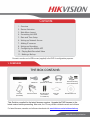
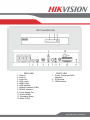
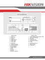
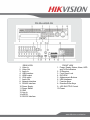
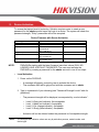
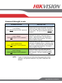
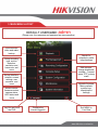
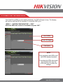
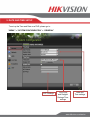
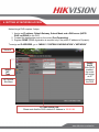
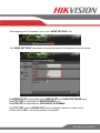
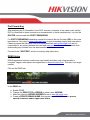
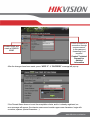
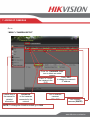
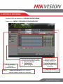
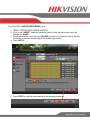
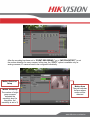
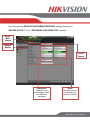
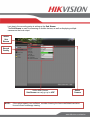
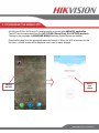
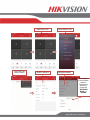
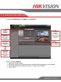
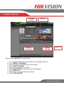
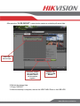
Quick Start Guide Turbo HD Series DVR DS-72xxHGHI-SH DS-73xxHQHI-SH DS-90xxHQHI-SH NOTE: For more information refer to the complete User Manual located on the CD-ROM © 2015 Hikvision USA Inc. All rights reserved. Hikvision is a registered trademark of Hikvision Digital Technology Co., Ltd. in the US, Canada, and other countries. All other trademarks, service marks, and product or service names are trademarks or registered www.hikvision.com/en/us trademarks of their respective owners. Product specifications and availability are subject to change without notice. Contents 1. Overview 2. Device Activation 3. Main Menu Layout 4. Formatting the HDD 5. Date and Time Setup 6. Setting up Network Access 7. Adding IP cameras 8. Setting up Recording 9. Configuring the Mobile APP 10. Playing Back Recorded Video 11. Making a Backup Connect a monitor and a USB mouse (supplied) to the DVR for configuration purposes. 1. OVERVIEW THE BOX CONTAINS: : DVR Hard Drive (Preinstalled) USB Mouse Hard Drive Cables IR Remote (Batteries not included) Rack Mount Ears (not included in 4-ch model box) Power Cord Quick Start Guide Hard Drive Mounting Screws and Brackets Manual/Software CD This Guide is compiled for the latest firmware versions. Upgrade the DVR firmware to the latest version before proceeding. Also note, the CD may contain outdated manuals and software For latest firmware, manuals, and software downloads visit: www.hikvision.com/en/us/download.asp www.hikvision.com/en/us DS-72xxHGHI-SH REAR VIEW 1. Video In 2. Audio In 3. Audio Out 4. VGA output 5. HDMI output 6. USB Interface 7. Network Interface (RJ45) 8. RS-485 Interface 9. Power Supply Port 10. Power Switch 11. Grounding Screw 12. Alarm In/Out FRONT VIEW 1. Power, Status and Tx/Rx indicators 2. IR Receiver 3. USB Interface www.hikvision.com/en/us DS-73xxHQHI-SH REAR VIEW 1. Video In 2. Video Out 3. Audio In 4. USB Interface 5. HDMI output 6. VGA output 7. Audio Out 8. Network Interface 9. RS-485 Interface 10. Power Supply 11. Power Switch 12. GND 13. Line In 14. eSATA 15. RS-232 Interface FRONT VIEW 1. Power, Ready, Status, Alarm, HDD and Tx/Rx Indicators 2. DVD-R/W 3. Composite Keys 4. Direction/Enter Keys 5. Power 6. Jog Shuttle Control 7. USB Interface 8. IR Receiver www.hikvision.com/en/us DS-90xxHQHI-SH REAR VIEW 1. Video In 2. Video Out 3. Audio In 4. USB Interface 5. HDMI output 6. VGA output 7. Audio Out 8. Network Interface 9. RS-485 Interface 10. Power Supply 11. Power Switch 12. GND 13. Line In 14. eSATA 15. RS-232 Interface FRONT VIEW 1. Power, Ready, Status, Alarm, HDD and Tx/Rx Indicators 2. IR Receiver 3. Front Panel Lock 4. DVD-R/W 5. Alphanumeric Buttons 6. USB Interfaces 7. Function Keys 8. Direction/Enter Keys 9. JOG SHUTTLE Control 10. Power www.hikvision.com/en/us 2. Device Activation To ensure the highest level of protection, Hikvision requires users to create a new password for the admin account upon first login to a device. The system will check the password strength; “Risky” passwords will not be accepted. Device Firmware with Secure Activation Device Type Value Series IP Camera Smart Series IP Camera NVR/Hybrid Plug-n-Play NVR Turbo DVR Super NVR NOTE: • Model Number DS-2CD2xxx DS-2CD4xxx DS-9016HWI-ST DS-96xxNI-ST DS-7716NI-SP/16 DS-76xxNI-EI(E2)/P DS-72xxHGHI-SH DS-73xxHQHI-SH DS-96128NI-E24/H DS-96256NI-E24/H Firmware Version V5.3.0 V5.3.0 V3.1.5 V3.1.0 V3.1.6 TBD DVRs/NVRs starting with the latest firmware (see chart, above) WILL NO LONGER HAVE A DEFAULT PASSWORD. The user must activate the DVR/NVR by creating a password for the admin account in one of four ways: Local Activation 1. Power on the DVR/NVR. - A message will appear, prompting user to activate the device. The username field will be greyed-out with the username set to admin. 2. Type in a password of your choosing (see “Password Strength Levels” table for guidelines). - The password strength will be displayed, accompanied by a color indicator: • • • • NOTE: Level 0–Risky (red indicator): Not acceptable Level 1–Weak (red indicator): Acceptable Level 2–Fair (orange indicator): Acceptable Level 3–Strong (blue indicator): Acceptable Activation will not be allowed unless the password is of acceptable strength. The strength level indicator colors can vary by activation process, model number, and device type. www.hikvision.com/en/us 3. Retype the password into the “Confirm Password” field. 4. After an acceptable password has been created, a confirmation message will appear on the screen. 5. Press the OK button to proceed. • SADP Software Activation (v2.2.3.5 or higher) 1. Launch the new version of the SADP software (v2.2.3.5). - The software will display all Hikvision devices on the network. A new field called “Security” will be displayed 2. If the DVR/NVR is “Inactive,” highlight the DVR/NVR and enter a new password into the “New Password” field on the bottom right of the screen. - The password strength will be displayed, accompanied by a color indicator: • • • • Level 0–Risky (no indicator): Not acceptable Level 1–Weak (pink indicator): Acceptable Level 2–Medium (yellow indicator): Acceptable Level 3–Strong (green indicator): Acceptable - Bar length indicates strength level. - Activation will not be allowed unless the password is of acceptable strength. If the password is unacceptable strength (“Risky”), a warning box will be displayed. 3. Retype the password into the “Confirm Password” field. 4. After the password has been entered and confirmed, press the OK button to display the pop-up confirmation window. 5. Press the “X” in the top right corner of the pop-up confirmation window to dismiss the window. www.hikvision.com/en/us • iVMS-4200 Windows Client Software (v2.3.1.3 or higher) Activation 1. Launch the iVMS-4200 software. 2. Go to Control PanelDevice Management. - On the bottom of the screen in the Online Devices section the screen will display all Hikvision devices on the network. - A new field called “Security” will be displayed. 3. If the DVR/NVR is “Inactive,” highlight the DVR/NVR and press the Activate button to display the “Activation” window. 4. Enter a new password into the “Password” field. - The password strength will be displayed, accompanied by a color indicator: • Level 0–Risky (no indicator): Not acceptable • Level 1–Weak (pink indicator): Acceptable • Level 2–Medium (yellow indicator): Acceptable • Level 3–Strong (green indicator): Acceptable - Bar length indicates strength level. - Activation will be allowed if the password is of acceptable strength. - If the password is of unacceptable strength (“Risky”), a warning box will be displayed explaining the requirements for an acceptable password. 5. Retype the password into the “Confirm Password” field. 6. After the password has been entered and confirmed, press the OK button. - The DVR’s/NVR’s status will change to “Active.” www.hikvision.com/en/us • Web Interface Activation 1. In a Web browser, type the DVR’s/NVR’s IP address and press Enter. - The Activation Window will appear instead of the login page. 2. Enter a new password into the “Password” field. - The password strength will be displayed, accompanied by a color indicator: • Level 0–Risky (no indicator): Not acceptable • Level 1–Weak (pink indicator): Acceptable • Level 2–Medium (yellow indicator): Acceptable • Level 3–Strong (green indicator): Acceptable - Bar length indicates strength level. - Activation will be allowed if the password is of acceptable strength. A white checkmark will appear in a green circle to the right of the password field. - If the password is unacceptable strength (“Risky”, a white X will appear in a red circle to the right of the password field and a warning dialog box will be displayed explaining the requirements for an acceptable password. 3. Press the OK button. - Upon successful activation, user will be logged in to the DVR’s/NVR’s live view page. www.hikvision.com/en/us Password Strength Levels STRENGTH LEVEL DESCRIPTION Level 0 (Risky) NVRs will not accept a Level 0 password Password length is fewer than eight characters, contains only one type of character, is the same as the user name, and/or is the mirror writing of the user name. This type of password will not be accepted. Level 1 (Weak) NVRs will accept a Level 1 password Password contains two kinds of characters. The combination is number + lowercase letter or number + uppercase letter, and the password length is at least eight characters. This type of password will be accepted. Level 2 (Medium/Fair) NVRs will accept a Level 2 password Password contains two types of characters. The combination is neither number + lowercase letter nor number + uppercase letter, and the password length is at least eight characters. This type of password will be accepted. Level 3 (Strong) NVRs will accept a Level 3 password Password contains more than three types of characters, and the password length is at least eight characters. This type of password will be accepted. NOTE: Types of characters are lowercase letters, uppercase letters, numbers, and special characters. Only ASCII characters are allowed. www.hikvision.com/en/us 3. MAIN MENU LAYOUT DEFAULT USERNAME: admin (Please note, the username and password are case sensitive) View recorded video and make backup Search for snapshots, make large backups Setup recording type, motion detection, resolution and frame rate, and more Add cameras, change brightness, contrast… camera name, PTZ, privacy mask Set up date/time, network, screen settings, user accounts, and more Upgrade firmware, factory default, system logs, import/export settings Model number, firmware version, camera status, HDD status and more Log Out and Lock the DVR Displays the current logged in user Exit MENU to Live View www.hikvision.com/en/us 4. FORMATTING THE HARD DRIVE If the Hard Drive (HDD) is not formatted (initialized), the DVR will begin to beep. The beeping will continue until the HDD is formatted. To format the HDD, go to: “MENU” > “SYSTEM CONFIGURATION” > “HDD” Select the HDDs that need to be formatted and press “INIT” List of HDDs Total HDD Space Free Space NOTE: Units purchased with HDDs come with HDDs already formatted. Formatting the HDDs also erases the recorded video from the HDDs (this does not affect the settings). www.hikvision.com/en/us 5. DATE AND TIME SETUP To set up the Time and Date on a DVR, please go to: “MENU” > “SYSTEM CONFIGURATION” > “GENERAL” NTP Settings Time Zone and Daylight Savings Time settings Date and Time settings www.hikvision.com/en/us 6. SETTING UP NETWORK ACCESS Networking a DVR requires 3 steps: 1. Assign an IP address, Default Gateway, Subnet Mask, and a DNS server (NOTE: DNS, not DDNS) to the DVR 2. Forward the appropriate ports on the router (Port Forwarding). 3. Register DDNS (DDNS registration is required only if the public IP address is Dynamic). To assign an IP ADDRESS, go to “MENU”>”SYSTEM CONFIGURATION”>”NETWORK” General Enable DHCP With DHCP enabled, the router will assign an IP address to the DVR Select NIC Type NETWORK Sub Menu IP CONFIGURATION Please note that the DVR’s default IP Address is 192.0.0.64 www.hikvision.com/en/us After assigning the IP information, click on the “MORE SETTINGS” tab. The “MORE SETTINGS” tab contains the ports that need to be forwarded for remote access. The SERVER PORT is responsible for the MOBILE APP and CLIENT SOFTWARE log-in. The HTTP PORT is responsible for WEB BROWSER log-in. The RTSP PORT is responsible for VIDEO/AUDIO STREAMING. The HTTP PORT and the SERVER PORT can be changed if desired, in order to avoid conflicts with the ISP or the existing network configuration. www.hikvision.com/en/us Port Forwarding After assigning the IP information to the DVR, connect a computer to the same router that the DVR is connected to (wired connection is recommended, to avoid complications). Log into the ROUTER, and proceed with PORT FORWARDING. For PORT FORWARDING assistance contact the Internet Service Provider (ISP) or the router manufacturer. Also refer to www.portforward.com for port forwarding step-by-step instructions. Please be aware that Hikvision USA is not associated with www.portforward.com and not responsible for any activity between the user and www.portforward.com. Please refrain from downloading any software from the abovementioned website. Proceed to the “ROUTERS” section for step-by-step instructions. DDNS Setup DDNS registration has been made more user friendly and takes only a few seconds to complete. Legacy units require user registration on www.hik-online.com. This step is no longer needed. Click on the DDNS tab. In the DDNS tab: a. b. c. d. Enable DDNS Change the DDNS TYPE to HiDDNS (in some cases HkDDNS) Make sure that the SERVER ADDRESS is set to www.hik-online.com Create a DEVICE DOMAIN NAME (the domain name CANNOT contain spaces, special characters and/or upper case letters www.hikvision.com/en/us Enable DDNS and create a DOMAIN NAME EZVIZ is used for a connection through a secure server. In this case port forwarding is not required. Contact Technical Support for detailed information After the changes have been made, press “APPLY.” A “SUCCESS” message will pop up. If the Domain Name does not meet the acceptable criteria, and/or is already registered, an error message will appear (the domain name cannot contain upper case characters, begin with a number, spaces, special characters…). www.hikvision.com/en/us 7. ADDING IP CAMERAS Go to: “MENU”>”CAMERAS SETUP” Press the “GARBAGE CAN” icon to delete an added camera Press “EDIT” Press “+” to add to change the camera’s the camera to the IP address. DVR Please refer to the manual for detailed information “REFRESH” to find cameras connected to the network List of detected cameras (YELLOW) List of added cameras (WHITE) NOTE: To change the CAMERA NAME go to OSD www.hikvision.com/en/us 8. SETTING UP RECORDING Hikvision DVRs are defaulted to CONTINUOUS RECORDING. Please go to: “MENU”>”RECORDING CONFIGURATION” Set Up Recording Schedule (Continuous/Motion) NOTE: The color of the calendar is what constitutes the recording schedule: 1. Blue=Continuous 2. Yellow=Event (Motion/Alarm) 3. Grey= No Recording If ENABLE SCHEDULE is not checked, then that camera would not be recording This field is used to customize a part of the existing schedule This can be ignored if setting up motion only recording Select the camera. Enable/Disable the schedule www.hikvision.com/en/us To set the DVR to MOTION RECORDING, go to: 1. “MENU”>”RECORDING CONFIGURATION” 2. Click on the “EVENT” under the calendar (yellow). After this the mouse cursor will change to a WAND. 3. Select the calendar, and it will turn YELLOW (just like on a computer, click on the topleft corner of the calendar and drag to the bottom-right corner). 4. Press APPLY. 5. Press COPY to copy the new schedule to the remaining cameras. www.hikvision.com/en/us After the recording has been set to “EVENT RECORDING,” go to “MOTION DETECT” to set the motion detection for every camera. In this step, the “COPY” option is available only for analog cameras, IP cameras need to be configured individually. Motion Detection Setup Motion Sensitivity The number of bright green squares indicates the sensitivity level (in this photo, the sensitivity is set to 3) Motion Area The grid indicates the area where motion will be detected www.hikvision.com/en/us To set the recording RESOLUTION/FRAMERATE/BITRATE settings, please go to: “RECORD QUALITY” in the “RECORDING CONFIGURATION” submenu. Select Main Stream Record Quality Select Camera Continuous Pertains to live view image as well as continuous recording Event Pertains to event recording only (motion or alarm) www.hikvision.com/en/us Stream Type enables/disables audio streaming from the camera (if the camera does not have audio capabilities, then the Stream Type will only have Video option). Resolution allows setting of the recording resolution. Bitrate Type allows the DVR to save HDD space when set to Variable (available choices: Variable and Constant) Video Quality adjusts picture clarity (medium setting/3 green squares) is recommended. Medium setting is the balance between good picture and saving HDD space). Frame Rate allows setting of the recording frame rate (12-15 fps is recommended to save HDD space and not to have a “choppy” image) Max Bitrate Mode allows choosing between preset bitrate values and customizing the values (General setting is recommended) Max Bitrate (KBPS) is the chosen bitrate for streaming the video. Max Bitrate Recommended is the DVR’s recommended bitrate according to the parameters set above. Record Audio allows turning the audio recording on or off (for IPC, this option is only available if the camera has a microphone connected to it). Video Stream allows changing the recording stream between Main Stream and Sub Stream (this step requires a restart). Input Resolution shows the resolution of video stream from camera. Recording Time (days) shows how much time left for recording, based on current HDD volume and recording parameters. Please refer to the table below for recommended recording parameters Resolution 320x240 (QVGA) 352x240 (CIF) 640x480 (VGA) 704x480 (4CIF) 1280x720 (720P) 1280x960 (960P) 1600x1200 (2MP) 1920x1080 (1080P) Video Quality Medium (3 squares) Medium (3 squares) Medium (3 squares) Medium (3 squares) Medium (3 squares) Medium (3 squares) Medium (3 squares) Medium (3 squares) Frame Rate (FPS) 12-15 12-15 12-15 12-15 12-15 12-15 12-15 12-15 Bitrate (KBPS) 207 384 768 1024 2048 2048 2560 3072 www.hikvision.com/en/us Last step in the recording setup is setting up the Sub Stream. The Sub Stream is used for streaming on mobile devices, as well as displaying multiple cameras on the local output. Select Sub Stream Record Quality Unlike Main Stream, Sub Stream can only go up to 4CIF NOTE: Select Camera If the upload speed is not sufficient, consider lowering the frame rate/bitrate/resolution for more fluent mobile app viewing. www.hikvision.com/en/us 9. CONFIGURING THE MOBILE APP All HikVision DVRs, NVRs and IP Cameras can be accessed with iVMS-4500 application. The APP can be downloaded from the APP STORE (iPhone/iPad), PLAYSTORE (Android). The app is also available for WINDOWS MOBILE devices (Nokia Phones and tablets). Download the app from the appropriate place and launch it. When the APP is launched for the first time, a tutorial screen will be displayed, and it can be easily skipped. Launch the APP Select your region www.hikvision.com/en/us “ADD” BUTTON Manual Adding “MENU” BUTTON DEVICES BUTTON ENTER THE INFO “REGISTER MODE” Please Note: If free HikVision DDNS is configured for the device, change the “REGISTER MODE” to HiDDNS www.hikvision.com/en/us CHANGE THE MODE ENTER “DEVICE DOMAIN” COMPLETE THE PAGE Please Note: Alias is just a friendly name for the address book (i.e. Home/Office) User Name and Password are the DVR’s/NVR’s username and password Please note: The “CAMERA NUMBER” is set to 1. After saving the changes, the number will resemble the correct amount of cameras “SAVE” BUTTON Please note: The “CAMERA NUMBER” has changed to the correct number of cameras connected to the DVR/NVR Please note: “START LIVE VIEW” button will begin live camera stream www.hikvision.com/en/us 10. PLAYING BACK RECORDED VIDEO To initiate a PLAYBACK, go to “MENU”>”PLAYBACK.” Select a camera to playback Select the desired date to playback Select the desired time of playback “Full Screen” button Going to a full screen will allow multiple channel playback Press PLAY to begin playback Click on the timeline to select the desired time of playback Steps to initiate PLAYBACK 1. Select the desired camera 2. Select the desired date (days that contain recording will be highlighted on the calendar) 3. Select the desired time using the Timeline or “Jump to Time” feature 4. Press “PLAY” www.hikvision.com/en/us 11. MAKING A BACKUP START/END Clipping Select the “START TIME” Save clip Select the “END TIME” Export Clips Steps to make a BACKUP of recorded video: 1. 2. 3. 4. 5. 6. 7. 8. 9. Insert a USB FLASH Drive or a USB HDD into an available USB Port Go to “MENU”>”PLAYBACK” Select the DATE and beginning time of the incident Click “START CLIPPING” Select the ending time of the incident Click “END CLIPPING” (same button as “Start Clipping”) Click “SAVE CLIP” Repeat steps 1-7 as many times as required Click “CLIPS EXPORT” www.hikvision.com/en/us After pressing “CLIPS EXPORT” a new window opens up containing all saved clips. Select the desired clips If selected, multiple clips created from the same camera will be stitched together EXPORT THE CLIPS TO USB DEVICE 10. Select the desired clips 11. Press “EXPORT” 12. After the backup is complete, remove the USB FLASH Drive or the USB HDD www.hikvision.com/en/us