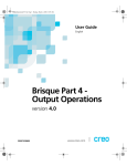
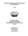
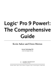
1
NEURON C N C E L E C T R O N I C S INDUSTRIAL TORCH HEIGHT CONTROL USER MANUAL NEURON CNC ELECTRONICS 21.09.2014 USER MANUAL System Description The Neuron.THC torch height control system is the most technologically advanced arc voltage control system in the plasma cutting industry. It is designed to offer arc voltage control capabilities to any plasma cutting system. The Neuron.THC quickly and accurately sets the arc transfer height of the torch using a “Ohmic” or “Float Head” plate sensing technique. The Neuron.THC system uses advanced DSP (digital signal processing) software servo control loops to control speed, position and arc voltage with unparalleled precision. The system is fully programmable via 10/100 Base-T Ethernet communications. The Neuron.THC can attain speeds in excess of 200 inches per minute in the arc voltage control mode and speeds in excess of 500 inches per minute in the position control mode. Safety Installation, as well as repairs, made to the Neuron.THC System should only be performed by qualified personnel. The Neuron.THC system use D.C. for operation. In addition, it will be necessary to make connections to the D.C. output of the plasma power supply. These voltages can be in excess of 300 volts. Fatal shock hazard does exist. Exercise extreme caution while working in these areas. Please refer to the plasma power supply manufacturer’s operating manual for additional information. Various other safety hazards exist while operating a plasma arc cutting system. Please see the plasma power supply manufacturer’s operating manual for information on eye, skin, and hearing protection, as well as other information required to safely operate the equipment. System Components The Neuron.THC System consists of the following components: Control module Plasma interface module Operator’s control module Mach3 Plugin and Screenset for plasma cutting applications Control module The control module houses a microcontroller, and I/O interface. This unit provides arc voltage control, and interfaces with the torch driver through the Pulse/Direction interface, the CNC Mach3 machine through the Ethernet interface, and the plasma system through standard discrete I/O interfaces. Plasma system interface module It provides precise, scaled feedback of the plasma arc voltage to the control module. It also provides a convenient control signal interface to the Neuron.THC. Operator Control Module The Operator Control Module includes an operating switches and a rotary/push knob selector for THC setup and control. USER MANUAL Specifications Input power 12V DC, 0.8A Operating temperature Operating humidity Pulse/Dir interace Ethernet communication -10º C to 40º C 95% relative humidity Open collector, protected +5V 100mA Shielded RJ-45 Cat-5e, Up to 100 m (4-wire Cat5e), I/O transmission speed 10/100 Mbps autonegotiation NO/NC dry contact Home switch, IHS switch and Ohmic sensor 15000 mm/min 10:1(internal), 20:1 (Hypertherm cutter) 25-250V 1 year Parallel digital input Lifter limit switches Maximum Z axis speed Voltage divider ratio Arc voltage range Warranty Control module has a size 145x90x45 mm with DIN mounting standard and can be easily embedded inside the CNC box. USER MANUAL Plasma interface board (Divider) Operator panel board USER MANUAL Features The Neuron.THC comes standard with the following features: Works with ALL plasma cutting systems Connect via 10/100 Base-T Ethernet interface to Mach3 CNC and controls Z axis directly (Internal motion controller, Software DSP (digital signal processing) control loop - 500 uS cycle) Unlimited number of cut profiles for different metal thicknesses. Quickly switch between profiles and the ability to quick edit them Set point resolution - .25V Set point range - 25 - 250V (set just by clicking the mouse button and wheel on the Target Arc Voltage textbox on Control Panel or turning the encoder knob on the operator panel) Maximum control accuracy - +/- .25V Height control accuracy +/-0.125 mm (.005") using a properly configured Z-axis. Voltage feedback (divider) - 1:20 (Hypitherm), 1:10 (internal) of Arc Voltage 100 kHz maximum step frequency (50% Duty cycle) Automatic or manual control of the cutting sequence Automatic Collision Avoidance. This safety feature allows the control to automatically adjust the torch height during a cut to help prevent torch crashes. Retract height selectable between full or programmed partial raise height Programmable automatic positioner speed Programmable manual positioner speed Programmable maximum Z axis stroke (Soft Limit function) Programmable arc transfer height Programmable pierce height Programmable pierce time Programmable cutting height Programmable AVC (arc voltage control) delay time Programmable torch retract height Programmable Jump height above the workpiece that the torch is raised to clear the top dross puddle that can form during the pierce. Programmable IHS (initial height sensing) touch speed Programmable crossover height (high-to-low speed transition point) Programmable AVC.OFF (Hold signal) control to help prevent torch crashing when end of cut, circle of small radius - enable/disable, mm. Programmable arc voltage limiter to help prevent torch crashing when crossing a kerf enable/disable, level, voltage Programmable arc voltage control loop proportional gain (system response) Sample voltage mode - THC measures the voltage at the end of the AVC Delay and uses it as a set point for the remainder of the cut. Skip IHS mode - If the next starting point is within this distance of the end of the previous cut, the THC skips the IHS. Improved Jog - the lifter initially jogs 0.25 mm. After 0.5 second, it begins continuous motion at the IHS Speed. After 1.5 seconds, the lifter increases the speed to the programmed Manual Speed Jog just by clicking the mouse button and wheel on the Position textbox or by pressing the up / down button on Operator Panel Buffered Step & Direction for direct interface to Motor Drive All inputs (include arc voltage) are isolated and Simple wiring (RJ45 connectors) Built-in pierce and cut time counter to control consumables Integrated diagnostic system informs the operator of the errors that occurred Plotting the arc voltage and save to file for diagnostics Easy Software update using the utility NeuronFlasher USER MANUAL System Requirements Power Requirements The Neuron.THC system has a terminal block power plug. 12V DC 0.8A required. Do not use 12V power from CNC PC! Use separated power supply. The performance of the Neuron.THC is tightly coupled to the lifter and motor characteristics. The Neuron.THC was designed as a conventional plasma height control and the lifter does not include any position feedback. The lifter screw pitch affects the lifter linear speed and the control loop gain when operating with arc voltage. The lifter friction and maximum torch weight affect the point at which the lifter will require a brake to maintain position. For these reasons, the motor and lifter characteristics are critical and must be tightly controlled. The following is a partial list of lifter and motor characteristics that are compatible with this controller. • Lifter Ball screw/Rack pitch = 4 – 20 mm/rev • Lifter with UP limit (homing sensor) • Lifter capable of 200 in/min. • Lifter should have low backlash and little mechanical play • If the functions are required the lifter should provide for the electrical interface to limit switches and torch tip sensing. WARNING: The performance of the Neuron.THC is tightly coupled to the lifter and motor characteristics. To ensure proper operation, a customer designed lifter should be fully tested with this controller under all anticipated operating conditions. USER MANUAL System Configurations USER MANUAL Input signal interface schematic Motor driver interface schematic Twisted pair cable with shield grounded on the driver side. USER MANUAL INSTALLATION 1. Mount the Neuron.THC into the CNC box. 2. Connect Home and Initial Height Sensing (Float Head and/or Ohmic Sensor) switches to screw terminals on the Control Module. 3. Connect the Mach3 CNC to the RJ45 (Cat5e) Ethernet connector on the Control Module (0.5 m minimal cable length). 4. Connect the plasma system interface module to the RJ45 (CAT5) connector on the Control Module. 5. Connect the Torch Lifter Driver to Pulse/Direction RJ45 connector on the Control Module. 6. Connect the power supply (DC 12 volt / 0.8A) to screw terminals on the Control Module. NOTE: All interconnection RJ45 cat5e cable has the PIN TO PIN connection. Recommended grounding and shielding practices Introduction This document describes the grounding and shielding necessary to protect a plasma cutting system installation against radio frequency interference (RFI) and electromagnetic interference (EMI) noise. It addresses the three grounding systems described below. Note: These procedures and practices are not known to succeed in every case to eliminate RFI/EMI noise issues. The practices listed here have been used on many installations with excellent results, and we recommend that these practices be a routine part of the installation process. The actual methods used to implement these practices may vary from system to system, but should remain as consistent as possible. Types of grounding 1. The safety, protective earth (PE), or service ground. This is the grounding system that applies to the incoming line voltage. It prevents a shock hazard to any personnel from any of the equipment, or the work table. It includes the service ground coming into the plasma system and other systems such as the CNC controller and the motor drivers, as well as the supplemental ground rod connected to the work table. In the plasma circuits, the ground is carried from the plasma system chassis to the chassis of each separate console through the interconnecting cables. 2. The DC power or cutting current ground. This is the grounding system that completes the path of the cutting current from the torch back to the plasma system. It requires that the positive lead from the plasma system be firmly connected to the work table ground bus with a properly sized cable. It also requires that the slats, on which the workpiece rests, make good contact with the table and the workpiece. 3. RFI and EMI grounding and shielding. This is the grounding system that limits the amount of electrical “noise” emitted by the plasma and motor drive systems. It also limits the amount of noise that is received by the CNC and other control and measurement circuits. This grounding/shielding process is the main target of this document. Steps to take 1. All motor and drive related leads need full shielding and twisted pair connectors. The shields should all be connected back to a star ground point at the driven ground rod. 2. Torch leads need to be shielded (outer cover with braided metal shield) that should be grounded only at the high frequency generator end.....back to the star ground point. The rest of the leads must be isolated from any machine metallic parts....preferably inside a plastic nonconductive power track. USER MANUAL 3. Chassis of plasma power supply (with high frequency generator should be mounted away (as far as practically possible) from the PC, and should be grounded directly to the star ground point. 4. PC should be as far away from the plasma power supply, should get its AC sourced through an uninterruptible power supply with surge protection. PC chassis should be grounded directly to the star ground point. 5. If a remote wired pendant is used, it should have a shielded cable, also grounded to the star ground point. 6. The gantry of the cutting machine should be grounded to the star ground point. 7. The torch carriage and z axis slide should be grounded to the star ground. 8. The computer monitor should be connected to the computer with a shielded cable. The mouse also needs to be shielded. Note: each ground wire to the star ground needs to be separate.....no "daisy chaining" as this can create ground loops. The work ground from the plasma should be bolted directly to the star ground (no welding clamp) The cutting slat bed should be connected directly to the star ground as well. The star ground point should be right on the ground rod, or within about 6 feet, any extra cable length should be shortened, no cables on the machine should have any coiled extra length. This is the minimum that should be done on any CNC installation with high frequency plasma.....this often, but not always, eliminates electrical noise interference problems! Voltage Divider Installation - General !!!! WARNING !!!! TURN OFF ALL POWER BEFORE WORKING ON EQUIPMENT The voltage divider provides a feedback signal which is derived from the actual cutting arc voltage of the plasma power supply. The Neuron.THC control uses this feedback signal to control the cutting height of the torch. The voltage divider used in the Neuron.THC a 10:1 signal. This simply means that a cutting voltage of 100 volts results in a signal of 10 volts provided to the control. The power supply positive and power supply negative connections on the voltage divider should be connected to the proper output points of the plasma power supply. USER MANUAL Powermax plasma unit. Internal divider 20:1 USER MANUAL Powermax plasma unit. Raw Arc Voltage. USER MANUAL Other plasma unit. Neuron internal divider. Setup Main module. USER MANUAL Connection to motor driver Neuron has +5V common protected open collector interface to motor driver. Twisted pair cable with shield grounded on the driver side. Use Cat6e shielded cable. One pair for Pulse signal (1 and 2 pins of the RJ45 plug) and one pair for Dir signal (3 and 4 pins of the RJ45 plug). The shield of the cable connects to the GND (chassis) of the motor driver (on the driver side). Shield on the other (Neuron) side of the cable leave free. USER MANUAL USER MANUAL LAN SETUP 1.) Go to [Control Panel]->[Network Connections] 2.) Right click on [Local Area Connection]->[Properties] USER MANUAL 3.) Select [Internet Protocol(TCP/IP)]->[Properties] 4.) Select [Use the following IP address:] and fill the fields. Set the IP address [XXX.XXX.XXX.1] (XXX.XXX.XXX – first three digit must be equivalent to controller IP address. For example controller has the 10.9.9.100 address. You have to set 10.9.9.1 IP address for the CNC computer. USER MANUAL Mach3 configuration For proper operation of the system is necessary to enable Torch Height Control Mach3 function by click on the THC ON button. Then after starting the program Mach3 must wait for the Motion signal from controller to begin moving on X/Y plane. NOTE: in not registered version of the Mach3 the THC function is disabled. USER MANUAL Functions and Definitions Main parameters The Mach3 Control panel screen that the operator sees during operation. NOTE: for edit the values you can click the right mouse button on DRO to open the input calculator. Parameter AVC Enabled Target Volts Real Volts Position Cut Height Pierce Height Pierce Delay Z0 button Profiles Select box Value When AVC is enabled (ON), Automatic Height Control is active. When AVC is disabled (OFF), the torch height sequences in Auto mode (IHS, Cut Height, Retract) but the torch height remains fixed during the cut and can changes with manual commands only. Click on the target voltage DRO on the Mach3 control panel and mouse wheel or rotate the selector switch on the operator panel to edit the Set Arc Voltage. The Neuron.THC system maintains the Set Arc Voltage during a cut in the Auto mode. Raising the Arc Voltage will increase the torch height during a cut, while lowering it will decrease the cutting height of the torch. The Arc Voltage can be adjusted from 50 to 250 volts in .25 volt increments. Real arc voltage Torch axis position mm or inches Inch or equivalent mm – 0.254 mm to 25.40 mm (0.01 in to 1.0 in). Click the right mouse button on this DRO to open the input calculator. Inch or equivalent mm – 0.254 mm to 25.40 mm (0.01 in to 1.0 in) . Click the right mouse button on this DRO to open the input calculator. 0 to 10 seconds with 0.01 second resolution. Click the right mouse button on this DRO to open the input calculator. Click on the Z0 button for start the torch homing procedure. If Z0 button is flash – the system wait the homing procedure. Click on the box and select the requirement cutting profile. USER MANUAL Torch Up button Torch Down button Full/Partial retract button Test button Neuron settings button Full IHS button Cut time, Pierce count, Reset button Run indicator Vent indicator ARCOK indicator Sampled indicator THC on checkbox Skip button Move Panel The lifter initially jogs up 0.254 mm (0.01 inch). After 0.5 second, it begins continuous upward motion at the IHS Speed. After 2 seconds, the lifter increases the speed to the programmed Manual Speed. Outputs do not change, if the torch is already cutting, it continues to cut. The lifter initially jogs down 0.254 mm (0.01 inch). After 0.5 second, it begins continuous downward motion at the IHS Speed. After 2 seconds, the lifter increases the speed to the programmed Manual Speed. The lifter does not change the output signals, if the torch is already cutting, it continues to cut. Click to switch on the torch full or partial retract after end of cutting. Click on this button to start test cutting without starting the plasma unit. Click on this button to open the Neuron settings window Click on this button for reset the last known workpiece position in IHS procedure. Next IHS procedure will be executed at the IHS speed. Cut time and Pierce count for consumables control. Click on the RESET button for clear values. Indicator for controller ready/run mode. Indicator for ventilation output state. Indicator for ARCOK input signal state. Indicator for Sample Mode state. - Sample Mode enabled - Arc voltage sampled success - Arc voltage sampled fail, using last stable value If this checkbox enabled – the system automatically enabled the “THC ON” Mach3 function when program start command issued. Set this for skip pierce procedure in cutting sequence. If this checkbox enabled you can change the position of the Control panel. USER MANUAL Neuron Cut profile window NOTE: for edit the values you can click the right mouse button on DRO to open the input calculator. Voltage Control Description: If Voltage Control is ON, the torch height is controlled by the measured arc voltage. If Voltage Control is OFF, the torch maintains a constant position during the cut that is independent of the Arc Voltage. Setting: OFF / ON Sample Voltage Description: The Voltage Control must be ON. When Sample Voltage is ON, the THC measures the voltage at the end of the AVC Delay or removing the Hold signal (from G-Code) and uses it as a set point for the remainder of the cut. When Sample Voltage is OFF the Set Arc Voltage is used as the set point for torch height control. Setting: OFF / ON Set Arc Voltage Description: The Voltage Control must be ON, and the Sample Voltage must be OFF. When Sample Voltage is OFF, the Set Arc Voltage is used as the set point for torch height control. Setting: 50 to 250 VDC Cut Height This value for the height at which the torch cuts the workpiece. Setting: 0.25 – 25.4 mm (0.01 – 1.0 in) Pierce Height Description: This value determines the height at which the torch pierces the workpiece. Setting: 0.25 – 25.4 mm (0.01 – 1.0 in) USER MANUAL Pierce time Description: This is the value for the Pierce Delay. During this time, the X/Y cutting motion is delayed to allow the plasma to fully pierce the workpiece. Setting: 0 – 10 seconds THC Response Description: This gain is used when the THC is operating closed-loop arc voltage control. How to use: If this value is set too high, the lifter positioning during closed-loop arc voltage control will become unstable and prone to oscillation. If this value is set too low, the arc voltage control can become slow and inaccurate. The value of 8 is appropriate. The THC Response can be tested by change value during cutting under closed-loop arc voltage control and checking that the THC quickly and accurately reaches the set arc voltage. Very high speeds on very thin or highly warped metal may require increasing the Response setting to respond faster. Be careful to not go so high the torch overshoots and oscillates up and down. Remember you will generally want to go back to 8 normal cutting. To optimize this response, raise this value until a very slight oscillation is detected during a cut and then reduce the setting by 1 or 2. Range: 1 to 30, the default setting = 8 LockHeadDown Description: This feature avoids that the plasma torch moves down which arc voltage is up (for example on the end of cut, when crossing a kerf or hole or going off the edge of the plate). If the adjustable Lock Head Down Level exceeds the limit during cutting, the clearance control will be disabled. Setting: OFF / ON LockHeadDown Level Description: When crossing a kerf or hole or going off the edge of the plate, arc voltage rises very rapidly. System will respond to the rise in voltage by lowering the torch trying to keep voltage constant. To prevent this an LockHeadDown Level is set so when arc voltage exceeds the cutting voltage by the % specified by the LockHeadDown Level setting system stops trying to control height. Hint: For thicker metal which tend to be fairly flat and using lower cutting speeds the arc voltage doesn’t change very rapidly except when crossing kerfs & holes so using a lower % will respond quicker, typically 5-10%. For higher speeds on thinner or warped metal where normal cutting voltage changes more rapidly, use a higher number around 10-15% or even 20%. Kerf Detect Description: When Kerf Detect is active, the THC looks for a rapid rise in the measured arc voltage that indicates that the torch is cutting across a previously cut kerf. This parameter temporarily disables the AVC and prevents the torch from diving into the workpiece. Setting: OFF / ON Kerf Detect Level Description: This parameter sets the sensitivity of the Auto Kerf Detection level on a relative scale. A value of 1 is the most sensitive and will activate at lower voltage increases, 15 is the least sensitive and will activate at higher voltage increases. Setting: 1 – 15 PreflowInIHS (professional version only) Description: When Preflow during IHS is ON, this saves cut-to-cut cycle time by allowing the plasma preflow time to occur during the IHS process. The PreflowInIHS relay is used in conjunction with the plasma start relay to start the plasma torch gas preflow during the IHS sequence. When the Neuron.THC receives a cycle start command, the PreflowInIHS relay closes immediately. Setting: OFF / ON USER MANUAL IHS Start Height Description: This is the height above the last known workpiece position that the THC switches from Automatic speed to the slower IHS speed. This height should be set high enough to avoid contacting the workpiece. Setting: 2.54 – 50.8 mm (0.1 – 2.0 in) Skip IHS Within Description: If the next starting point is within this distance of the end of the previous cut, the THC skips the IHS. When this happens, the torch goes directly to the Transfer Height and skips contact with the workpiece. This setting can improve the overall machine production rate but should not have any affect on the part being cut. Clear the checkbox to disable this feature. Setting: 0 – 3000 mm Transfer Height Description: This value determines the height above the workpiece where the torch is initially fired. It is the torch height after an IHS and is entered as a percentage of the Cut Height. This setting can be used to improve the ability of the torch to transfer to the workpiece for processes that use a very high Pierce Height or have difficulty in transferring. Setting: 50% – 400% of Cut Height, commonly 150% Retry on transfer fail Description: This value determines the number of times that the controller will attempt to re-start the plasma after failing to transfer. The controller removes and reapplies the start signal on each re-start attempt. Setting: 0 – 10 Transfer time Description: This is the number of seconds that the controller will wait for transfer before attempting a retry. Setting: 0 – 10 seconds Jump Height Description: This value determines the height above the workpiece that the torch is raised to clear the top dross puddle that can form during the pierce. It is the torch height after Pierce. This height is entered as a percentage of the Cut Height. The torch remains at this height until the Jump Time Delay has elapsed. If this feature is not used, clear the Enabled checkbox. Setting: 50% – 450% of Cut Height Jump Time Description: This value sets the number of seconds to hold the torch at the Puddle Jump Height before transitioning to the Cut Height. This time is used to allow the torch to clear the top dross puddle that forms during a pierce. If this feature is not used, clear the Enabled checkbox. Setting: 0 – 10 seconds AVC Delay Description: This value sets the number of seconds that are required for the cutting machine and plasma torch to achieve steady-state operation at the cut height. After this delay, the AVC is enabled for the remainder of the cut. If the THC is in Sample Voltage mode and Hold signal is removed, the arc voltage sample is taken after this delay. Setting: 0 – 10 seconds Retract Height Description: This parameter specifies height above the workpiece to which the torch retracts at the end of a cut. Setting: 2.54 mm – the maximum lifter length USER MANUAL G-Code AVC control Description: This feature enables AVC ON/OFF control from G-Code by commands E5P0/E5P1 (SheetCamTNG Code Snippets option). This significantly improves the process of cutting the corners, circles and at end of the cut. Setting: OFF / ON Disable AVC Description: This feature disables AVC control on the corners, small holes and at the end of a cut (internal hardware function). Neuron Settings window Automatic Speed Description: This speed is used for all automatic rapid moves such as the End-of-Cut-Retract or the Initial Approach to the workpiece. This value depends on the lifter motor speed, the screw pitch, the weight of the lifter load and the desired speed of operation. Manual Speed Description: Manual speed is the speed at which the positioner moves when the control is in the manual mode. Note that in Manual, the positioner moves at a IHS speed when the up/down buttons are initially pressed. The speed is increased to the manual speed if the buttons are held down. IHS Speed Description: This parameter sets the slow speed for the final approach to the workpiece during an IHS operation. It is also used as the slow speed for manual moves. Acceleration Description: This acceleration is used for all automatic, manual and IHS moves. This value depends on the motor parameters, the weight of the lifter load and the desired speed of operation. USER MANUAL Acceleration in Cut Description: This acceleration is used for moves during arc voltage close-loop operation. This value depends on the motor parameters, the weight of the lifter load and the desired speed of operation. Typically this value is equal to the Acceleration. Slide Length Description: This value is the length of the lifter’s usable travel (Soft Limit function). Safe Jog Height Description: This value is the length of the lifter’s travel in % from Home position, when torch will be move on the Manual speed. The rest of the slide length, torch will be move at the IHS speed. Pulse Per Turn Description: The value is based on the counts of pulses for motor driver, it is equal to the number of pulses per revolution. Unit Per Turn Description: The value is based on the ball-screw pitch, it is equal to the distance of Move the torch per revolution. Average Filter Time Description: This value is the time constant of the arc voltage average filter. Setting: 1 – 63 msec. Dead Band Description: This value is an interval of an arc voltage where no AVC occurs. Setting: 0.25 – 3.0 V. Clear Plate Distance Description: This value is the distance where system expects the Ohmic or Float head clear plate signal in IHS procedure. Settings: 0 – 20 mm Reverse Direction Description: Set this checkbox to reverse torch move direction. Use Ohmic Sensor Description: The ohmic sensor feature allows the Neuron.THC to sense when the torch shield cap, nozzle, or other sensing device has touched the plate. It is used to accurately set the initial pierce height of the torch. For plasma systems that do not have plate sensing capability, the ohmic sensor feature can be turned off. In this case, the Float Head is used for setting the initial pierce height of the torch, with some trade-off in IHS repeatability. Automatic Collision Avoidance This safety feature allows the control to automatically adjust the torch height during a cut to help prevent torch crashes. If automatic collision avoidance is enabled, the arc voltage is automatically increased any time contact is sensed between the torch and the plate, provided that the Use Ohmic function is enabled. If the torch contacts the plate while a Hold signal is applied, the torch retracts to the programmed Cut Height, provided that the Use Ohmic function is enabled. USER MANUAL Input for THC Hold signal Selection Select the how the controller will get the HOLD signal (disable automatic voltage control) from the Mach3 CNC. Software – HOLD signal will be received by plugin software (maximum delay is 100 msec). Hold or Float Head or Ohmic inputs - HOLD signal will be receive by hardware hi-speed input port (maximum delay is 1 msec). This mode should be selected if you are using a motion controller (SmoothStepper, HiCON, CSMIO, Apollo or other), or you cutting metal at Hi speeds of more than 4000 mm/min. USER MANUAL If you use Ethernet Smooth Stepper, you have to configure Ouput#5 signal for M10/M11 commands. USER MANUAL Neuron Diagnostic window USER MANUAL Control State IDLE Homing Soft Limit IHS FAST APPROACH IHS SLOW APPROACH WORKPIECE CONTACT IHS RETRACT START PLASMA PIERCE START PIERCING PUDDLE JUMP CUT PREPARE SAMPLE CUTTING MANUAL UP MANUAL DOWN RETRACT In this state, the plasma system is OFF, the motor is holding position. The system waits for the Cycle Start input signal and enters either the IHS Fast Approach state or the IHS Slow Approach state, depending on whether the workpiece position is known. The lifter moves the torch up at the programmed IHS Speed till the Upper Limit Switch. The THC enters this state when the actual position is the programmed Slide Length. The motor is stopped and the torch maintains its position. Only up motion is allowed during this state. The torch moves down at the programmed Automatic Speed to the Start IHS Height then enters the IHS Slow Approach state. The lifter continues to move down at IHS Speed, using Ohmic or float head sensor, until the lifter receives the Tip Sense input signal. When the THC receives the Tip Sense input signal, it enters the Workpiece Contact state. The torch lifter begins to move up slowly until Ohmic sense or float head contact is clear. The lifter then records the workpiece position and enters the IHS Retract state. The lifter moves up at the programmed Automatic Speed to the Transfer Height. The lifter holds the torch at the IHS Transfer position, waits for the Transfer input signal from the plasma system, and then enters the programmed Pierce Start state. The lifter moves the torch to Pierce Height. When the torch is in position, the lifter enters the Piercing state. The lifter holds the torch at the Pierce Height for the Pierce Delay interval. When Pierce Delay is complete, the lifter enters the Puddle Jump state if it enabled or Cut Prepare State. The lifter moves the torch to the Puddle Jump Height. It waits for Puddle Jump Delay, and then enters the Cut Prepare state The lifter moves the torch to the Cut Height and sends the Mach3 Motion signal to begin X/Y cutting motion. The THC waits for the AVC Delay and then enters either the Sample state or the Cutting state, depending on the operating mode The controller receives a new Arc Voltage sample for this cut. It modifies the operating Arc Voltage Control set point and enters the Cutting state. If AVC ON Mode is active and the Hold signal from the Mach3 CNC is not active, the lifter controls the torch height using arc voltage feedback. If AVC OFF Mode is active operator can adjust the torch height by rotating the encoder on the operator panel. If Ohmic contact sense is enabled, the torch retracts if it makes Ohmic contact. When the cut is complete and the Cycle Start input signal from the CNC is deactivated, the THC enters the retract state. The lifter initially jogs up 0.25 mm. After 0.5 second, it begins continuous upward motion at the IHS Speed. After 2 seconds, the lifter increases the speed to the programmed Manual Speed. Outputs do not change, if the torch is already cutting, it continues to cut. The lifter initially jogs down 0.25 mm. After 0.5 second, it begins continuous downward motion at the IHS Speed. After 2 seconds, the lifter increases the speed to the programmed Manual Speed. The lifter does not change the output signals, if the torch is already cutting, it continues to cut. The lifter moves the torch up at Automatic Speed to the Retract Height. When the torch is in position at the Retract Height and enters the Idle state. USER MANUAL Sequence of Operation 1. Operator runs the work program by click on the “START” button on the Mach3. 2. The Mach3 CNC control move torch (x/y) to the IHS start position and wait the Motion signal from the controller. “RUN” indicator on the Neuron control panel is flash. 3. Operator turn ON the “Cutting Start” switch on the operator panel. 4. The torch travels towards the plate at Automatic speed and switches to the IHS Speed when the crossover IHS Height is reached. The torch touches the plate at the IHS Speed. 5. The torch immediately retracts to the Arc Transfer Height. 6. Plasma Start signal is issued to the power supply. 7. The power supply initiates an arc and the Neuron.THC receives a Transfer signal from the power supply. 8. The torch moves to the Pierce Height and the Pierce Time timer is initiated. 9. When the Pierce Time elapses, the torch moves to the Cut Height. 10. The Neuron.THC issues a Motion signal to the x/y machine. 11. The x/y machine begins profiling the part. 12. The AVC Delay timer is initiated. 13. AVC Delay time starts. If sample mode enabled THC is sampling the arc voltage, at end of AVC Delay or after removing the Hold signal from CNC. THC uses the last stable sampled voltage as a reference to control height for rest of cut. If sample mode is disabled THC uses the Set Arc voltage as a reference to control height. 14. The programmed Arc Voltage, thus the torch height, can be increased and decreased while in AVC ON by rotating the encoder on the operator’s panel or click on the target voltage DRO on the Mach3 control panel and mouse wheel. AVC mode is disabled, thus freezing the torch height, any time a Hold signal is received (from G-Code). 15. If AVC is disabled (AVC OFF) the torch height, can be increased and decreased by rotating the encoder on the operator’s panel or click on the Position DRO on the Mach3 control panel and mouse wheel. 16. If Head Safety Lock is enabled, AVC mode is disabled any time a sudden increase in arc voltage is sensed, such as when crossing a kerf or running off the plate. 17. If collision avoidance is enabled, the arc voltage is automatically increased any time contact is sensed between the torch and the plate, provided that the Ohmic function is enabled. If the torch contacts the plate while a Corner signal is applied, the torch retracts to the programmed Cut Height USER MANUAL 18. When the Cycle Start signal is removed from the Neuron.THC, the torch retracts to the Full Raise or Partial Raise Height depending on the Partial/Full setting. Initial Setup After the Neuron.THC system is installed, perform the following setup sequence to ensure proper operation. 1. Open the settings window by clicking button. 2. Move to the tab «Settings» and click on the «Change Settings» button. It opens Motion control configuration. 3. Set parameters of the motor driver «pulse per turn» (numbers of pulses for one turn of the torch driving shaft) and «mm per turn» (distance which torch will pass per one turn of the torch driving shaft). 4. To apply changing click on the “Save Settings” and then “Hardware Reset” for restarting the controller. Restart Mach3. 5. Click button after restarting and select the tab “Diagnostics”. 6. Check the homing, IHS, Ohmic sensors inputs, “Cutting Start” switch. If sensor is activated you will see green indicator on the “check inputs” field. You can select type of the sensor and inputs signals N.O. or N.C. 7. In IDLE mode all sensor is off and all led is gray. 8. Turn on motor driver power supply. Clicking the buttons torch “UP/DOWN” on the control panel or operator control module make sure that torch moving in the correct direction. If not – set “Reverse Direction” checkbox on the Motion control group. 9. Click button. System will be starting the homing procedure. 10. Move the torch down as it possible (buttons UP/DOWN). Copy the value of the torch position and put it in the “Slide Length” box (Soft Limit function). 11. Set up the maximum values of the acceleration and velocity of the torch moving as your system allowed (avoid lost steps for steppers motors). Usually Acceleration in cut is equivalent acceleration. 12. Set up manual and IHS velocity. 13. Set up “safe height Jog” in percent’s of “Slide Length” value. “Safe height Jog” is the distance from home position where the fast jog is allowed. Below this point the torch will move with IHS velocity only. 14. Tune up the Float Head: Put the sheet of metal. Thickness not less 3 mm. Open the settings window by clicking button. Move to the tab «Settings» and set the check box «start» in the field “Float Head correction”. Controller begins IHS procedure. When the IHS procedure completed the torch will be moved up in the 4mm. for metric system or 0.2 in for inches system. 15. Check the distance between the surface of the metal and torch nozzle. If it not 4mm (0.2 in.) (check it for example by standard drill) correct it by rotating encoder on the operator control module. To finish it clear the check box start. 16. Connect plasma interface PCB with plasma unit according the scheme in the manual. USER MANUAL Pre-Cut Setup Before making a cut with the Neuron.THC system, perform the following setup sequence to ensure proper operation. 1. From the Mach3 Neuron control panel, edit the Arc Voltage. Enter the recommended arc voltage for the material being cut. The system can also be placed in the “Sample Voltage” mode. In “Sample Voltage” mode, the system maintains the actual feedback arc voltage that corresponds to the Cut Height at the time the Hold signal is removed at the start of a cut and the AVC Delay time has expired. 2. Edit the Arc Transfer Height. Enter the recommended arc transfer height for the material being cut. If this data is not listed for thinner materials, try setting the arc transfer height to the same value as the pierce height. For thicker materials, try setting the arc transfer height to one-half the pierce height. 3. Edit the Pierce Height. Enter the recommended pierce height for the material being cut. If this data is not listed for thinner materials, set the pierce height the same as the cutting height. For thicker materials, try setting the pierce height to 1.5 or 2 times the cutting height. 4. Edit the Cut Height. Enter the recommended cutting height for the material being cut. 5. Edit the Pierce Time. Enter the recommended pierce time for the material being cut. The pierce time should be adjusted such that the torch moves from the pierce height to the cutting height after the arc pierces completely through the workpiece. 6. Place the system in the correct cutting modes desired (AVC ON/OFF, Test/Run, Full/Partial Raise). 7. Now a cut can be made with the Neuron.THC system. Verify the status of the LED’s on the Cutting sequence chart during operation. Auto Lost Cut Recovery Description: Your machine will move to where the arc signal was lost and begin cutting. When to Use: • Your plasma torch was on, but you lost the arc signal. • You want to re-start where the arc signal was lost. WARNING: Your machine will move to the last location where an arc signal was lost. Make sure that your torch had been on. If not done properly, this mode could cause severe damage to your machine and/or material. Manual Lost Cut Recovery Description: Your machine will begin cutting at the current location and then continue executing from the line of G-Code you selected. When to Use: • Your torch never started (there never was an arc ok signal). • You cannot start at the position that lost the arc signal. • You want to start between two lines of G-Code. WARNING: Your machine will pierce and then start cutting at the current position. USER MANUAL Lost Cut Recovery Buttons If at any time you need to start executing your program from some point other than at the beginning, start by pressing STOP. Auto Lost Cut Recovery 1. Press Lost Cut Recovery 2. Then select Auto. . 3. Select Yes to begin or No to change the feedrate. 4. If you selected No previously, update your feedrate and press OK. 5. Your machine will move to where the arc was lost, re-reference the Z axis, and then begin cutting. USER MANUAL Manual Lost Cut Recovery 1. Scroll through the G-Code until you locate the line where you want your program to begin 6. Cutting or press the Backup/Forward buttons. 2. Move the machine to the EXACT X and Y position where you want the machine to begin cutting (press on the Simulation button , then START button. On desired position press on the STOP button). 3. Press Lost Cut Recovery. 4. Then select Manual. 5. Select Yes to begin. Your machine will make the IHS procedure and then begin cutting from the current location. USER MANUAL Common cutting faults Fault Transfer Fail Failed to completely pierce the workpiece and there is excessive sparking on top of the workpiece. Dross forms on the bottom of the cut. Cut angle is not square. Short consumable life. Part is the wrong size. Possible causes 1. Work cable connection on the cutting table is not making good contact. 2. Torch-to-work distance is too high. 3. The surface of the workpiece is rusty, oiled, or painted. 1. Current is set too low (check Cut chart information). 2. Cut speed is too high (check Cut chart information). 3. Torch parts are worn (change consumable parts). 4. Metal being cut is too thick. 5. The surface of the workpiece is rusty, oiled, or painted. 6. Pierce Delay is set too low. 1. Cutting speed is not correct (check Cut chart information). 2. Arc current is set too low (check Cut chart information). 3. Torch parts are worn (change consumable parts). 1. Wrong direction of machine travel. The high-quality side is commonly on the right with respect to the forward motion of the torch. 2. Torch-to-work distance is not correct (check Cut chart information). 3. Cutting speed is not correct (check Cut chart information). 4. Arc current is not correct (check Cut chart information). 5. Damaged consumable parts. 6. The torch is not mounted perpendicular to the workpiece. 7. Damaged torch. 1. Arc current, arc voltage, travel speed, motion delay, gas flow rates, or initial torch height was not set as specified in the cut charts. 2. Attempting to cut highly magnetic metal workpiece, such as one with a high nickel content, will shorten consumable life. Long consumable life is difficult to achieve when cutting a workpiece that is magnetized or becomes magnetized easily. 3. Beginning or ending the cut off the surface of the workpiece. To achieve consumable long life, all cuts must begin and end on the surface of the workpiece. The Kerf value is set incorrectly. USER MANUAL How to optimize cut quality The following tips and procedures will help produce square, straight, smooth and dross-free cuts. Tips for table and torch: Use a square to align the torch at right angles to the workpiece. The torch may travel more smoothly if you clean, check and “tune” the rails and drive system on the cutting table. Unsteady machine motion can cause a regular, wavy pattern on the cut surface. The torch must not touch the workpiece during cutting. Contact can damage the shield and nozzle, and affect the cut surface. Plasma set-up tips Follow carefully each step in the operating cycle for each operating mode, described earlier in this section.Purge the gas lines before cutting. Maximize the life of consumable parts The long life requires that cuts start and stop on the workpiece. • The torch should never fire into the air. – Start the cut at the edge of the workpiece is acceptable, as long as the arc is not fired in the air. – To start with a pierce, use a pierce height that is 1.5 to 2 times the torch-to-work distance. • Each cut should end with the arc still attached to the workpiece. – When cutting drop parts (small parts that drop down after being cut from the workpiece), check that the arc stays attached to the edge of the workpiece. Note: Use a continuous cut between parts if possible, so the path of the torch can lead directly from one cut part into the next, without stopping and starting the arc. However, do not allow the path to lead off the workpiece and back on, and remember that a chain cut of long duration will cause electrode wear. Additional factors of cut quality Cut angle A cut part whose 4 sides average less than 4° of cut angle is considered acceptable. Note: The squarest cut angle will be on the right side with respect to the forward motion of the torch. Note: To determine whether a cut-angle problem is being caused by the plasma system or the drive system, make a test cut and measure the angle of each side. Next, rotate the torch 90° in its holder and repeat the process. If the angles are the same in both tests, the problem is in the drive system. If a cut-angle problem persists after “mechanical causes” have been eliminated check the torchto-work distance, especially if cut angles are all positive or all negative. • A positive cut angle results when more material is re moved from the top of the cut than from the bottom. • A negative cut angle results when more material is removed from the bottom of the cut. USER MANUAL Dross What is dross? Dross is molten metal that does not blow away during the cutting process and instead adheres to the bottom or top of the part in a re-solidified state. There are many factors that can contribute to the accumulation of dross. The most common are: cutting speed, torch standoff height or damaged consumables. In most instances, dross can be reduced or eliminated completely by adjusting the cutting speed to the optimum condition as prescribed in the operator’s manual. However, there may be times when a simple speed adjustment is not possible or will have little effect, such as when the thickness of the material or the cutting amperage requires a slow cutting speed. In this case, dross accumulation is inevitable and cannot be eliminated. Also, the quality, grade and composition of the material are factors that can increase the likelihood of dross and are outside of the control of cutting parameters. For example, a lower quality sheet of carbon steel may be more susceptible to dross buildup due to the increased level of impurities. Finally, as the temperature of the plate increases from the plasma cutting process, dross is more likely to stick to the bottom even with optimum parameters. High Speed Dross Cause: When the programmed cutting speed is too fast for the amperage being used or the material thickness being cut, the bottom of the arc will lag behind the top. When this happens, the high pressure gas found at the orifice of the nozzle is not as effective at material removal, allowing small amounts of dross to form on the bottom of the plate. High speed dross is typically dotted in appearance and cannot be removed easily by scraping with a hand tool. It must be removed by grinding or machining the finished part. Solution: Verify the cutting speed for the selected amperage, material type and thickness. If it already does, decrease the cutting speed in small increments (5-10 inches per minute) until the best result is achieved. Select a lower cutting amperage Examine the electrode and nozzle for excessive wear and replace as needed. USER MANUAL Low Speed Dross Cause: If the cutting speed is too slow for the material thickness or selected amperage, a solid line of dross that resembles a weld bead will form on the bottom of the part. To understand why, remember that the plasma cutting process is electrical in nature. When the torch is moving too slowly, the arc begins to expand in an effort to maintain contact with the edge of the kerf in order to keep its path to ground through the plate. As the arc widens, the distance from the cut edge to the high pressure section of the plasma jet increases to the point where the gas is no longer able to blow away the material effectively. Low speed dross is easily removed with a hand scraping tool. Solution: Verify the cutting speed for the selected amperage. If it already does, increase the cutting speed in small increments (2-5 in. per minute) until the best result is achieved. Select a higher cutting amperage and adjust the parameters accordingly. Examine the nozzle and shield cap for damage and replace as needed. USER MANUAL Corner Dross Cause: Dross will intermittently form in the corners of a part due to the speed reduction required for a cutting machine to perform an extreme change in direction, such as a right angle. The likelihood of this occurring varies depending on the thickness of the material, cutting amperage, and material composition. Solution: This is a normal occurrence and cannot be avoided without altering the part drawing to include options such as corner loops. Fortunately, the amount of dross this condition presents is minimal and is easily removed with a hand scraping tool. Top Dross Cause: Occasionally, small amounts of dross will form on the top of the part when the programmed cutting speed is too fast or the torch standoff distance is too high. This is caused by the plasma arc’s inability to blow all the molten metal through the bottom of the kerf when the tip of the USER MANUAL nozzle is too high above the plate. Top dross is normally a very light accumulation that can be removed easily with a scraping tool. Solution: 1. Reduce cutting speed in 5 in. per minute increments, while monitoring for the introduction of low speed dross. 2. Lower the arc voltage setting in 2 volt increments. 3. Check the nozzle for damage and replace as needed. Additional improvements Some of these improvements involve trade-offs, as described. Piercing The pierce delay should allow sufficient time to penetrate the full thickness of the material, but not so long that it allows the arc to “wander” while trying to find the edge of a large pierce hole. As consumables wear, this delay time may need to be increased. Pierce delay times given in the cut charts are based on average delay times throughout the life of the consumables. When piercing materials close to the maximum thickness for a specific process, there are several important factors to consider: • Allow a lead-in distance that is about the same as the thickness of the material being pierced. 50 mm (2 in) material requires a 50 mm lead-in. • To avoid damage to the shield from the build up of molten material created by the pierce, do not allow the torch to descend to cut height until it has cleared the puddle of molten material. • Different material chemistries can have an adverse effect on the pierce capability of the system. In particular, highstrength steel and steel with a high manganese or silicon content can reduce the maximum pierce capability. • Starting torch motion immediately after transfer and during the pierce process can extend the piercing capability of the system in some cases. Because this can be a complex process that can damage the torch or other components, a stationary or edge start is recommended. USER MANUAL How to increase cutting speed Decrease the torch-to-work distance. This will increase the negative cut angle. Note: The torch must not touch the workpiece while piercing or cutting. The thin lines are almost straight and at an angle of 15-30 degrees. The cutting speed and Arc current is correct. Lines are not straight and have a curved form in the upper part and further parts directed vertically as shown in Figure. The cutting speed is low. Increase the cutting speed. Lines are not straight and have a curved form in the lower portion of the part as shown. The cutting speed is too high or arc current is too low.