1
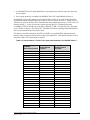
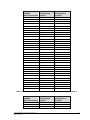
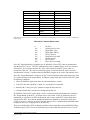
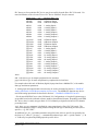
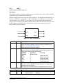
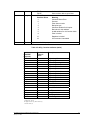
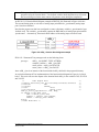
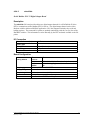
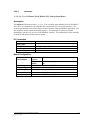
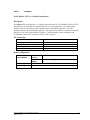
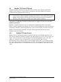
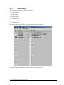
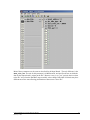
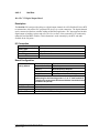
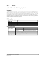
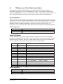
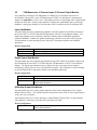
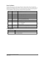
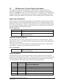
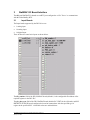
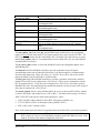
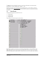
parameter can only be used when a single “PLC Device” port is configured on the SCADAPack
RTU.
4.4.2
Output Boards
ISaGRAF Slave PLC output boards typically require user configuration through the I/O board
parameters. These are set as part of the ISaGRAF application and are entered into the I/O board
parameter fields within the ISaGRAF Workbench I/O Connections editor.
Typical fields are:
board_address: specifies the Slave PLC data registers to access when writing from ISaGRAF
variables to PLC data. The PLC data type accessed is specific to the Slave PLC I/O board and board
address. This value is usually the PLC’s data (or register) address.
plc_data_type: specifies the PLC data register type. Currently IEC UINT type is supported for
analog boards and IEC DISCRETE type is supported for Boolean boards. Other data types may be
supported in the future. See specific PLC driver interface manuals for more information.
plc_device_addr: Some PLC device drivers support multi-drop PLC devices on the same
communication channel, or have unique addressing identifiers. Where the PDS driver provides
multi-drop support, ISaGRAF may access data from any of the locally multi-dropped devices. A
separate I/O board will be required for each device.
must_write_rate: The unit for this parameter is driver specific, and configures the rate at which the
data for the Output board is written to the PLC. Between “must_write_rate” periods, data is written
to the PLC only when the ISaGRAF output variable values change. Individual I/O boards may have
different must write rates allowing prioritization of data sent to a slave PLC.
timeout: PLC device drivers with comprehensive I/O board interfaces may provide a parameter for
specifying the communications timeout on an individual I/O board (i.e. the timeout applies to
communications associated with that board). Where this value is “0”, the PLC device driver will use
a default timeout. The units for this field are dependent upon the PLC device driver. Units may be,
for example, milliseconds, seconds, minutes, etc.
port: this parameter may be on a PLC slave I/O board for a device driver. Where present, it defines
which of multiple RTU “PLC Device” ports will be used to communicate with the PLC or peripheral
device. If only one “PLC Device” port is configured, this field is ignored. ISaGRAF Slave PLC I/O
boards that do not include this parameter can only be used when a single “PLC Device” port is
configured on the SCADAPack RTU.
4.4.3
Board Status
The SCADAPack E Series RTU checks for data being written to the PLC by ISaGRAF, before the
Slave PLC input board data is retrieved. Communication requests made by the SCADAPack E Series
RTU to the PLC are asynchronous to the scanning of the ISaGRAF application, but data within
ISaGRAF remains consistent duration of a scan cycle.
To assist with debugging of ISaGRAF Slave PLC I/O board communication, the SCADAPack E
Series RTU provides two types of analog system points which provide useful information:
1. PLC Communication Status
Status available for the first 60 ISaGRAF Slave PLC I/O Boards used in ISaGRAF kernel 1, and the
first 14 ISaGRAF Slave PLC I/O Boards used in ISaGRAF kernel 2.
2.
Cache Time (seconds)
E Series ISaGRAF Technical Reference Manual
February 7, 2006
28