1
14 SuperBrush Owner’s Manual
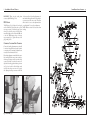
Wrapping Abrasive Strips
Note: When using Pre-Marked™ or Pre-Cut™
abrasives, not all of the steps below are necessary.
Servicing Your SuperBrush 23
4. With the trailing edge of the strip properly cut,
rewrap the drum and insert the tapered end through
the slot in the right (inboard) end of the drum.
Insert the tapered end into the inboard take-up
fastener. Pull up on the clip lever to open the clip,
and pull the take-up lever to the top as shown (Fig.
12-g). After inserting the strip end, release the clip
lever by moving your index finger toward the drum
slot. This allows the clip to retain the abrasive while
holding the take-up lever in an “up”position.
Proper attachment of the abrasive strip to the drum
is critical to achieving top performance from your
SuperMax Tools drum sander. Abrasive strips do not
have to be pre-measured. The end of the roll is first
tapered and attached to the left (outboard) side of the
drum. Then the strip is wrapped around the drum,
and the second taper is made for attachment to the
5. The take-up fastener is designed to automatically
right (inboard) side of the drum. To attach a strip to
take up any slack caused by stretching of the
the drum, follow the procedure below.
abrasive strip. Important: Position the abrasive
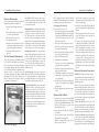
1. Mark and cut a taper at one end of the roll as
strip in the slot with sufficient room between the
shown in Fig. 12a. Because the tapered end should
inside of the slot and the tapered end of the strip to
use most of the left (outboard) slot width, its end
allow it to be pulled into the drum as needed (Fig.
must be trimmed (Fig. 12-b and 12-c). Raise the
12-h). Note that not leaving enough space between
clip lever on the left (outboard) side of the drum
the strip and the inside of the slot will prevent the
(Fig. 12-d). Insert the tapered end through the slot
take-up fastener from operating properly.
and into the fastener so that it uses most of the
6. The abrasive strip may stretch enough in use to allow
width of the slot. Release the clip lever to securely
the take-up lever to reach its lowest position so it no
hold the strip end in the fastener.
longer is able to maintain tension on the strip (Fig.
2. Wrap the strip around the drum, being careful
12-i). If this occurs, it will be necessary to reset the
not to overlap the windings. The tapered cut of
take-up lever by raising it, pushing the strip end into
the strip end should follow the edge of the drum.
the slot, and then releasing the clip lever.
Continue to wrap the abrasive in a spiral fashion by
Note: A sandpaper cleaning stick may be used to
rotating the drum with your left hand and guiding
remove deposits and help extend sandpaper life. To
the strip with your right hand (Fig 12-e). Successive
use, operate the sanding drum with the dust cover
windings of the strip should be flush with previous
open. (Caution: For your own safety, always wear eye
windings without any overlap.
protection while performing sandpaper cleaning, and
3. Mark the trailing end of the strip where it crosses the take all precautions to avoid any contact of hands or
right (inboard) end of the drum (Fig. 12-f ). From clothing with uncovered drums.) Hold the cleaning
this point, cut a taper as was done with the starting stick against the rotating drum and move it along the
edge of the strip. (The taper on the remaining roll drum surface. It is good procedure to use a shop brush
can be used as the taper for the starting edge of the to remove any cleaning stick crumbs from the drums
next strip to be cut.)
before resuming sanding operations.
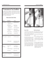
Step 1. Check the conveyor drive and driven roller to
make sure it is parallel to the surface of the conveyor
bed. To do this, first center the conveyor belt on the
bed. Then lay a straight-edge on the exposed edge
of the conveyor table on the left (outboard) side,
extending it over the drive or driven roller. Note the
distance between the drive or driven roller and the
straight-edge.
Step 2. Now repeat Step 1 on the right (inboard) side
of the conveyor. Compare the measurements from
side to side. If they are not equal, loosen one of the
brackets that hold the drive or driven roller in place.
Tip this bracket until the distance between the drive
roller and the straight-edge are equal from side to side,
then tighten the bracket.
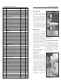
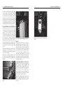
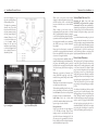
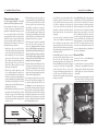
Conveyor Belt Tension: To adjust the tension of
the conveyor belt, first adjust the take-up screw nut
(Fig. 21) on both sides of the conveyor to obtain
approximately equal tension on both sides of the belt
when taut. Insufficient belt tension will cause slippage
of conveyor belt on the drive roller during sanding
operation. The conveyor belt is too loose if it can
be stopped by hand pressure applied directly to the
top of the conveyor belt. Excessive belt tension can
result in bent rollers, premature wearing of the bronze
bushings or conveyor belt
Conveyor Belt Tracking: Belt tracking adjustments
are made while the conveyor belt is running. After the
proper belt tension is obtained (see above), turn the
conveyor unit on and set it at the fastest speed setting.
Watch for a tendency of the conveyor belt to drift to
one side of the conveyor. To adjust the belt tracking,
tighten the take-up screw nut (Fig. 21) on the side
the belt is drifting toward, and loosen the take-up
screw nut on the opposite side. Adjusting the take-up
screw nuts on either side of the conveyor allows belt
tracking adjustments to be made without affecting
belt tension. Note: Adjust the take-up screw nuts
only 1/4 turn at a time. Then allow time for the belt
to react to the adjustments before proceeding further.
Try to avoid over-adjustments.
Replacing V-Belt
To change the V-belt on the SuperBrush, first
disconnect power source to machine.
1. Lower the main motor to its lowest position using
the brush speed control handle. Raise the motor to
its highest position. This will loosen the V-belt in
the drive pulley so the V-belt can be lifted off the
driven pulley.
2. Remove the miter gear from the right (inboard) side
of the transfer rod (Fig. 14). (If E clips are attached
to the rod, remove both at this time.) Now loosen
CU
SANDPAPER STRIP
(ABRASIVE SIDE UP )
Also see Fig. 12-b and Fig. 12-c.
Fig. 12a Marking and cutting taper on strip.
T L
INE
S
15
3/4
"
3"
Approx. 3"
Fig. 20 Conveyor belt replacement.
Fig. 21 Tensioning and tracking conveyor belt.