1
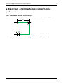
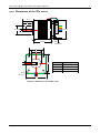
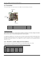
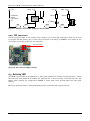
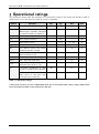
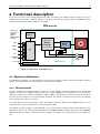
MECHATRONIC DRIVES WITH STEPPER MOTOR PANdrives Hardware Version V1.3 HARDWARE MANUAL + + TMCM-110-42 controller / driver up to 1.1A RMS / 24V RS232, RS485 or CAN stallGuard™ + + + + PDx-110-42 full mechatronic device up to 1.1A RMS / 24V RS232, RS485 or CAN stallGuard™ NEMA17/42mm stepper motor + TRINAMIC Motion Control GmbH & Co. KG Hamburg, Germany www.trinamic.com + PD-110-42 / TMCM-110-42 Manual (V1.19/2012-FEB -20) Table of contents 1 2 3 4 5 6 7 8 Features ........................................................................................................................................................................... 4 Order codes .................................................................................................................................................................... 6 Electrical and mechanical interfacing ..................................................................................................................... 7 3.1 Dimensions ........................................................................................................................................................... 7 3.1.1 Dimensions of the TMCM-110-452 ........................................................................................................ 7 3.1.2 Dimensions of the PDx-110-42 .............................................................................................................. 8 3.2 Connectors ............................................................................................................................................................ 9 3.2.1 Connector 1: power supply and host interface ............................................................................... 9 3.2.2 Connector 2: motor ................................................................................................................................ 11 3.2.3 Connector 3: additional I/O ................................................................................................................. 11 3.2.4 ISP connector........................................................................................................................................... 12 3.3 Activity LED ......................................................................................................................................................... 12 Operational ratings .................................................................................................................................................... 13 Functional description .............................................................................................................................................. 14 5.1 System architecture .......................................................................................................................................... 14 5.1.1 Microcontroller......................................................................................................................................... 14 5.1.2 EEPROM ...................................................................................................................................................... 15 5.1.3 TMC428 motion controller .................................................................................................................... 15 5.1.4 TMC246 motor driver ............................................................................................................................. 15 5.2 Power supply...................................................................................................................................................... 15 5.3 Communication interfaces .............................................................................................................................. 15 5.3.1 RS232 .......................................................................................................................................................... 16 5.3.2 RS485 .......................................................................................................................................................... 16 5.3.3 CAN ............................................................................................................................................................. 16 5.3.4 I2C ................................................................................................................................................................ 16 5.4 Reference switches ........................................................................................................................................... 16 5.5 stallGuard™ - sensorless motor stall detection ....................................................................................... 17 5.6 Motor current setting ....................................................................................................................................... 17 5.7 Microstep resolution......................................................................................................................................... 17 5.8 Optimum motor settings ................................................................................................................................ 18 Operational description ............................................................................................................................................ 19 6.1 Calculation: Velocity and acceleration vs. microstep- and fullstep frequency ............................. 19 Revision history .......................................................................................................................................................... 21 7.1 Document revision............................................................................................................................................ 21 7.2 Hardware revision ............................................................................................................................................. 21 7.2.1 RS232, RS485, I2C interface version .................................................................................................. 21 7.2.2 CAN interface version ............................................................................................................................ 21 References .................................................................................................................................................................... 22 Copyright © 2012, TRINAMIC Motion Control GmbH & Co. KG 2 PD-110-42 / TMCM-110-42 Manual (V1.19/2012-FEB -20) 1 Life support policy TRINAMIC Motion Control GmbH & Co. KG does not authorize or warrant any of its products for use in life support systems, without the specific written consent of TRINAMIC Motion Control GmbH & Co. KG. Life support systems are equipment intended to support or sustain life, and whose failure to perform, when properly used in accordance with instructions provided, can be reasonably expected to result in personal injury or death. © TRINAMIC Motion Control GmbH & Co. KG 2009-2012 Information given in this data sheet is believed to be accurate and reliable. However neither responsibility is assumed for the consequences of its use nor for any infringement of patents or other rights of third parties, which may result from its use. Specifications are subject to change without notice. Copyright © 2012, TRINAMIC Motion Control GmbH & Co. KG 3 PD-110-42 / TMCM-110-42 Manual (V1.19/2012-FEB -20) 4 2 Features The PD-110-42 consists of an intelligent stepper motor controller and driver module mounted directly on a 42mm flange motor (NEMA 17). The TMCM-110 module converts the motor into a compact mechatronic device with bus oriented or stand-alone control. The motor, switches, power and the multipurpose I/Os can be connected via small pluggable connectors. The TMCM-110 comes with the PC based software development environment TMCL-IDE for the Trinamic Motion Control Language (TMCL™). Using predefined TMCL™ high level commands like move to position or constant rotation a rapid and fast development of motion control applications is guaranteed. The TMCM-110 can be controlled via an RS232, RS485, I²C or CAN interface (ordering option). Communication traffic is kept very low since all time critical operations, e.g. ramp calculation, are performed on board. The TMCL™ program can be stored in the on board EEPROM for standalone operation. The firmware of the module can be updated via the serial interface. With the integrated stallGuardTM feature it is possible to detect motor overload or motor stall. Electrical data up to 1.1A coil current RMS (1.5A peak) 7V to 34V motor supply voltage supports two phase bipolar motors with 0.3A to 1.1A coil current PANdrive motor data Specifications Units Rated Voltage Rated Phase Current Phase Resistance at 20°C Phase Inductance (typ.) V A Ω mH Ncm oz in mNm g cm2 Kg Holding Torque (typ.) Detent Torque Rotor Inertia Weight (Mass) Insulation Class Dielectic Strength (for one minute) Connection Wires Step Angle Step angle Accuracy (max.) Flange Size (max.) Motor Length (max.) Rear shaft hole depth Rear shaft hole diameter Axis Diameter Axis Length (typ.) Axis D-cut (0.5mm depth) Maximum Radial Force (20 mm from front flange) Maximum Axial Force Ambient temperature VAC N° ° % mm mm mm mm mm mm mm -35-10-027 5.3 1.0 5.3 6.6 27 38 22 35 0.22 B 500 4 1.8 5 42.3 33.5 5.0 3.0 5.0 24 20 QSH4218 -41-10-035 4.5 1.0 4.5 7.5 35 50 25 54 0.28 B 500 4 1.8 5 42.3 38 5.0 3.0 5.0 24 20 -51-10-049 5.0 1.0 5.0 8.0 49 69 28 68 0.35 B 500 4 1.8 5 42.3 47 5.0 3.0 5.0 24 20 N 28 28 28 N °C 10 -20…+50 10 -20…+50 10 -20…+50 Table 2.1: Motor technical data Interface RS232, RS485, I²C or CAN 2.0a host interface 2 inputs for reference and stop switches 1 general purpose input and 1 output Copyright © 2012, TRINAMIC Motion Control GmbH & Co. KG PD-110-42 / TMCM-110-42 Manual (V1.19/2012-FEB -20) Features up to 16 times microstepping memory for 2048 TMCL™ commands automatic ramp generation in hardware on the fly alteration of motor parameters (e.g. position, velocity, acceleration) stallGuard™ for sensorless motor stall detection full step frequencies up to 20kHz dynamic current control TRINAMIC driver technology: No heat sink required Software stand-alone operation using TMCL™ or remote controlled operation PC-based application development software TMCL-IDE included Other pluggable JST connectors RoHS compliant Copyright © 2012, TRINAMIC Motion Control GmbH & Co. KG 5 PD-110-42 / TMCM-110-42 Manual (V1.19/2012-FEB -20) 6 3 Order codes The RS232 and RS485 interfaces are assembly options of one and the same TMCM-110 printed circuit board. The TMCM-110-42-CAN module has a dedicated printed circuit board. Cables are not included. Add the appropriate cable loom to your order if required. Order code PD1-110-42 (-option) PD2-110-42 (-option) PD3-110-42 (-option) TMCM-110-42 (-option) Description PANdrive 0.27Nm PANdrive 0.35Nm PANdrive 0.49Nm Motion control module Table 3.1: PANdrive or module order codes Option -232 -485 -CAN Host interface RS232 interface RS485 interface CAN interface Table 3.2: Options for order codes Component parts TMCM-110-CABLE Description Cable loom for module and PANdrive. Table 3.3: Order codes for component parts Copyright © 2012, TRINAMIC Motion Control GmbH & Co. KG Dimensions [mm³] 53 x 42 x 42 59 x 42 x 42 69 x 42 x 42 15 x 42 x 42 PD-110-42 / TMCM-110-42 Manual (V1.19/2012-FEB -20) 4 Electrical and mechanical interfacing 4.1 Dimensions 4.1.1 Dimensions of the TMCM-110-452 The overall height of the module is 15mm. Please note that connectors on the front are upright. 41.91 5.4 5.4 M3 41.91 M3 5.4 5.4 Figure 4.1: Board dimensions and mounting holes (all dimensions in millimeters) Copyright © 2012, TRINAMIC Motion Control GmbH & Co. KG 7 PD-110-42 / TMCM-110-42 Manual (V1.19/2012-FEB -20) 8 4.1.2 Dimensions of the PDx-110-42 24±1 20 4.5 42 max 42.3 22-0.05 5 2 Length 17 max Connectors 31 20 5 42.3 PD1 PD2 PD3 PD4 4xM3 Deep 4.5 42.3 Figure 4.2: Dimensions of the PDx-110-42 Copyright © 2012, TRINAMIC Motion Control GmbH & Co. KG Length of motor 33.5±1mm 38±1mm 47±1mm 60±1mm PD-110-42 / TMCM-110-42 Manual (V1.19/2012-FEB -20) 9 4.2 Connectors The connector type is JST 2mm PH series. The TMCM-110 has the following connectors: Connector 2 Pin 1 Connector 3 Pin 1 Pin 1 Connector 1 Connector 1 Connector 2 Connector 3 Power supply and host interface Motor Additional I/O JST PHR-5 JST PHR-4 JST PHR-8 Figure 4.3: Connectors of the TMCM-110 (RS232 version) Connecting the module Never connect or disconnect a motor when the module is powered, as this may damage the module. Also, the motor driver is not protected against short circuits to ground. To integrate the TMCM-110 on a user board, you can choose universal high precision female header rows, like Fischer electronic BLY1.50Z. The pin of the module has a square of 0.5mm * 0.5mm. To compensate for the height of the power capacitor on the TMCM-110, one hole is required at the corresponding position (diameter >=8 mm). 4.2.1 Connector 1: power supply and host interface Use this connector to connect the power and the host interface (RS232, RS485, IIC or CAN). The pin assignments are different for the four available versions of the module: Pin 1 2 3 4 5 RS232 GND +7..34V DC GND RxD TxD Function RS485 IIC GND GND +7..34V DC +7..34V DC GND GND RS485+ SCL RS485 SDA CAN GND +7..34V DC GND CAN + CAN - Table 4.1: Connector 1 Copyright © 2012, TRINAMIC Motion Control GmbH & Co. KG PD-110-42 / TMCM-110-42 Manual (V1.19/2012-FEB -20) 10 4.2.1.1 RS485 interface version The RS485 interface version of the TMCM-110-42 includes an on-board RS485 bus termination resistor (120Ohm). The resistor can be enabled by setting a jumper (as in figure 4.4). In that case the 120 Ohm resistor will be placed between the two RS485+ and RS485- bus wires. Please note that termination is required for the first and the last node of an RS485 network. For all other nodes in-between the bus termination jumper has to be removed. Otherwise communication might be impossible or unreliable. RS485 bus termination jumper Figure 4.4 RS485 bus termination jumper (RS485 version) 4.2.1.2 CAN interface version The CAN interface version of the TMCM-110-42 includes an on-board CAN bus termination resistor (120Ohm). The resistor can be enabled by setting a jumper (as in figure 4.5). In that case the 120 Ohm resistor will be placed between the two CAN+ and CAN- bus wires. Please note that termination is required for the first and the last node of a CAN network. For all other nodes in-between the bus termination jumper has to be removed. Otherwise communication might be impossible or unreliable. CAN bus termination jumper Figure 4.5: CAN bus termination jumper (CAN version) Copyright © 2012, TRINAMIC Motion Control GmbH & Co. KG PD-110-42 / TMCM-110-42 Manual (V1.19/2012-FEB -20) 11 4.2.2 Connector 2: motor Connect a two-phase bipolar stepper motor to this connector. The pin assignment of this connector is as follows: Pin 1 2 3 4 Function Phase A1 Phase A2 Phase B1 Phase B2 Table 4.2: Connector 2 4.2.3 Connector 3: additional I/O All other inputs and outputs of the module can be connected here. These are the limit switches, a general purpose input and a general purpose output. The limit switch inputs are equipped with internal pull-up resistors, so they have to be connected to GND via normally closed switches. The general purpose input can either be used as a digital TTL input or as an analogue input (0…5V). The general purpose output is an open collector output for a maximum current of 100mA. A freewheeling diode is also included so that e.g. a relay or a coil can be connected directly. Please note that the freewheeling diode is connected to the supply voltage and not to +5V, so when using e.g. a relay that is connected to +5V a freewheeling diode must be connected externally. The pin assignment of this connector is as follows: Pin 1 2 3 4 5 6 7 8 Name StopL StopR GND GPO VDD GND GPI +5V Function Left limit switch input (integrated 10K pull up to 5V) Right limit switch input (integrated 10K pull up to 5V) Signal Ground General purpose output 0 (open collector, max. 100mA, max. 40V) VDD (same as connector 1, pin 2) Signal Ground General purpose input (Analog / Digital) +5V DC output (max. 20mA) Table 4.3: Connector 3 GPO VDD 1k GPI BC846 µC GND 10k +5V Figure 4.6: Wiring scheme for GPO and GPI Copyright © 2012, TRINAMIC Motion Control GmbH & Co. KG PD-110-42 / TMCM-110-42 Manual (V1.19/2012-FEB -20) + 5V 12 max. VS Pushbutton, Switch, Light barrier, etc. + 5V max. VS 150 optional Relais A C C E L-793ID GPI GPO GPO GPO Figure 4.7: Examples for possible wirings for GPI and GPO 4.2.4 ISP connector The 6pin (2x3pin) header on the module is the connector for an Atmel ISP programmer which can be used to program the CPU directly. This is done during production and testing at TRINAMIC, only. Please do not use and do not connect anything to this connector. ISP connector Figure 4.8: ISP connector (RS232 version) 4.3 Activity LED The TMCM-110-42 module is equipped with an LED. Some TMCM-110-42 modules are equipped with a yellow LED and some other TMCM-110-42 modules are equipped with a red one. During normal operation this LED flashes. After resetting the configuration EEPROM it maybe takes some seconds before the LED starts flashing. When the operating system is being downloaded to the module the LED is permanently on. Copyright © 2012, TRINAMIC Motion Control GmbH & Co. KG PD-110-42 / TMCM-110-42 Manual (V1.19/2012-FEB -20) 13 5 Operational ratings The operational ratings show the intended / the characteristic range for the values and should be used as design values. In no case shall the maximum values be exceeded. Symbol Parameter Min Typ Max Unit VS Power supply voltage for operation 7 12… 30 34* V ICOIL Motor coil current for sine wave peak (chopper regulated, adjustable via software) (adjust via Software) 0 0.4… 1.5 1.5 A IMC Continuous motor current (RMS) 0 0.3... 1.1 1.1 A fCHOP Motor chopper frequency IS Power supply current U+5V +5V output (max. 20mA load) VGPO Open collector output, max. 100mA, freewheeling diode included VINPROT Input voltage for StopL, StopR, GPI0 (internal protection, DC) VANA GPI0 analog measurement range VSTOPLO StopL, StopR low level input VSTOPHI StopL, StopR high level input (integrated 10k pull-up to +5V) 1.9 TENV Environment temperature at rated current (no forced cooling required) -40 45 °C Environment temperature at 80% of rated current or 50% duty cycle (no forced cooling required) -40 60 °C 36.8 4.8 -24 kHz << ICOIL 1.4 * ICOIL A 5.0 5.2 V VS V 24 V 0…5 0… 5 0 V 0.9 5 V V Table 5.1: Operational ratings * Please make sure that you have a TMC246A-PA driver chip on the module when using a supply voltage above 28.5V. All modules produced in 2006 and later have this chip. Copyright © 2012, TRINAMIC Motion Control GmbH & Co. KG PD-110-42 / TMCM-110-42 Manual (V1.19/2012-FEB -20) 14 6 Functional description In Figure 4.1 the main parts of the PDx-110-42 module are shown. The module mainly consists of the µC, a TMC428 motion controller, a TMC246 stepper motor driver, the TMCL™ program memory (EEPROM) and the optional host interfaces (RS232, RS485, IIC and CAN). PDx-110-42 Choose one out of four interface options before placing an order: TMCL Memory Step progammable CAN Motion Controller RS232 with TMC428 High Power Driver TMC246 +5V µC RS485 Motor I2C additional I/Os 12… 30V DC 2 Stop Switches 5V Power Supply TMCM-110-42 Figure 5.1: Main parts of the PDx-110-42 6.1 System architecture The TMCM-110 integrates a microcontroller with the TMCL™ (Trinamic Motion Control Language) operating system. The motion control real-time tasks are realized by the TMC428. 6.1.1 Microcontroller On this module, the Atmel ATmega32 is used to run the TMCL™ operating system and to control the TMC428. The CPU has a 32Kbyte flash memory and a 1Kbyte EEPROM. The microcontroller runs the TMCL™ operating system which makes it possible to execute TMCL™ commands that are sent to the module from the host via the interface. The microcontroller interprets the TMCL™ commands and controls the TMC428 which executes the motion commands. The flash ROM of the microcontroller holds the TMCL™ operating system. The EEPROM memory of the microcontroller is used to permanently store configuration data. The TMCL™ operating system can be updated via the host interface. Please use the latest version of the TMCL-IDE to do this. As already mentioned above the TRINAMIC CANnes CAN-Bus PCI-Card or the TRINAMIC USB-2-X interface converter is needed to connect modules with CAN or I2C interfaces to the PC to update the OS. Copyright © 2012, TRINAMIC Motion Control GmbH & Co. KG PD-110-42 / TMCM-110-42 Manual (V1.19/2012-FEB -20) 15 6.1.2 EEPROM To store TMCL™ programs for standalone operations the TMCM-110 module is equipped with a 16kByte EEPROM attached to the microcontroller. The EEPROM can store TMCL™ programs consisting of up to 2048 TMCL™ commands. 6.1.3 TMC428 motion controller The TMC428 is a high-performance stepper motor controller. It can control up to three 2-phase-steppermotors (on this module, only one motor can be used). Motion parameters like speed or acceleration are sent to the TMC428 via SPI by the microcontroller. Calculation of ramps and speed profiles are done internally by hardware based on the target motion parameters. 6.1.4 TMC246 motor driver The TMC246 motor driver is very dependable, because it provides a variety of protection and diagnostic features, which can be read out by the user software. The 16 times up to 32 times microstepping gives a quiet and precise motor operation. As the power dissipation of the TMC246 is very low no heat sink or cooling fan is needed. The temperature of these chips does not get too high easily. The coils will be switched off automatically when the temperature or the current exceed the limits. They are automatically switched on when the values are within the limits again. 6.2 Power supply The TMCM-110-42 is equipped with a linear voltage regulator that generates the 5V supply voltage for the digital components of the module from the motor power supply. Because of that only one supply voltage is needed for the module. The power supply voltage can be 12… 30 V DC. A higher voltage gives higher motor dynamics. Please note that there is no protection against reverse polarity or too high voltage. When using supply voltages near the upper limit of 34V, a regulated power supply becomes a must. Please ensure, that enough power filtering capacitors are provided in the system (470µF or more recommended per motor), in order to absorb mechanical energy fed back by the motor in stalling conditions. The power supply should be designed in a way, that it supplies the nominal motor voltage at the desired maximum motor power. In no case shall the supply value exceed the upper/lower voltage limit. To ensure reliable operation of the unit, the power supply has to have a sufficient output capacitor and the supply cables should have a low resistance, so that the chopper operation does not lead to an increased power supply ripple directly at the unit. Power supply ripple due to the chopper operation should be kept at a maximum of a few 100mV. This also is important in order to make the user’s application compatible to any applicable EMC guidelines. Therefore we recommend to keep power supply cables as short as possible use large diameter for power supply cables use a robust 470µF or larger additional filtering capacitor located near to the motor driver unit, if the distance to the power supply is large (i.e. more than 2 - 6m) 6.3 Communication interfaces The communication between the host and the module takes place via its host interface. This can be RS232, RS485, I2C or CAN. Please note that the TMCM-110-42 module can only be equipped with one of these interfaces. Communication with the TMCM-110-42 module is done using TMCL™ commands. The interface the module is equipped with is ready-to-use, so there are no external drivers or level shifters necessary. Copyright © 2012, TRINAMIC Motion Control GmbH & Co. KG PD-110-42 / TMCM-110-42 Manual (V1.19/2012-FEB -20) 16 6.3.1 RS232 To connect the RS232 interface of a PC to the module you can use a extension cable or null modem cable (twisted, with female plugs at both ends). The difference is shown in Table 5.6.1. Female (Host) 1 2 3 4 5 6 7 8 9 Null modem Female 4 3 2 1 5 6 8 7 9 Modem Male 1 2 3 4 5 6 7 8 9 Signal RxD TxD GND Table 5.6.1: RS232 connection to PC 6.3.2 RS485 For RS485 communication we recommend to use our USB-2-485 converter for fast communication. This converter switches to receive mode right after the last bit has been sent, without any delay. The pause time can be set to 0. It is also equipped with an RS485 termination network. Not using the USB-2-485 a pause time between commands and a termination network may be necessary. The telegram pause time value is milliseconds ±5%. This time depends on the converter used. Converters controlled by the RTS line need about 15ms, sometimes 25ms. An RS485 termination network (1k from RS485+ to +5V, 1k form RS485- to GND, 100R between RS485+ and RS485-) may be necessary for faster communication, for longer distances, and it is recommended in any case. 6.3.3 CAN To use the TMCL-IDE with CAN interface either the TRINAMIC CANnes card or the Trinamic USB-2-X interface converter is needed. Otherwise an additional CAN termination of 120 Ohms between CAN high and CAN low (at both ends of the cable) may be necessary. 6.3.4 I2C To use the I2C interface with the TMCL-IDE the Trinamic USB-2-X interface is required. 6.4 Reference switches Two digital reference/stop switch inputs are provided (StopL = stop left and StopR = stop right). They are used as an absolute position reference for homing and to set a hardware limit for the motion range. The inputs have internal pull-up resistors. Either opto-switches or mechanical switched with normally closed contact can be used. The 5V output can be used as a supply for opto-switches. Copyright © 2012, TRINAMIC Motion Control GmbH & Co. KG PD-110-42 / TMCM-110-42 Manual (V1.19/2012-FEB -20) 17 6.5 stallGuard™ - sensorless motor stall detection The integrated stallGuard™ feature gives a simple means to detect mechanical blocking of the motor. This can be used for precise absolute referencing, when no reference switch is available. The load value can be read using a TMCL™ command or the module can be programmed so that the motor will be stopped automatically when it has been obstructed or the load has been too high. Just activate stallGuard™ and then let the traveler run against a mechanical obstacle that is placed at the end of the operation area. When the motor has stopped it is definitely at the end of its way, and this point can be used as the reference position. Please see the PDx-110-42 Firmware Manual on how to activate the stallGuard™ feature. The TMCL-IDE also has some tools which let you try out and adjust the stallGuard™ function in an easy way. Mixed decay should be switched off when stallGuard™ is used in order to get good results. 6.6 Motor current setting The motor current can be set in a range of 0… 1500, using the TMCL™ software. 1500 corresponds to the module’s maximum ICOIL setting. Setting ICOIL,PP ICOIL,RMS 1500 1410 1100 800 600 400 0 1.5A 1.41A 1.1A 0.8A 0.6A 0.4A 0A 1.06A 1.0A 0.8A 0.6A 0.4A 0.3A 0A Table 5.6.2: Motor current examples 6.7 Microstep resolution The microstep resolution can be set using the TMCL™ software. The default setting is 64 microsteps (which is the highest resolution). For setting the microstep resolution with TMCL™ use instruction 5: SAP, type 140: microstep resolution. You can find the appropriate value in Table 5.6.3: Value 0 1 2 3 4 5 6 microsteps Do not use: For fullstep please see fullstep threshold Halfstep (not recommended) 4 8 16 32 64 Table 5.6.3: Microstep resolution setting Despite the possibility to set up to 64 microsteps, the motor physically will be positioned to a maximum of about 24 Microsteps, when it is operated with 32 or 64 microstep setting. Copyright © 2012, TRINAMIC Motion Control GmbH & Co. KG PD-110-42 / TMCM-110-42 Manual (V1.19/2012-FEB -20) 18 6.8 Optimum motor settings The following settings apply best for highest motor velocities with smooth motor behavior at low velocities. Mixed decay should be switched on constantly. The microstep resolution is 4 [TMCL], this means 16 times microstepping. The pulse devisor is set to 3. Optimum Motor Settings Motor current (RMS) Motor voltage Maximum microstep velocity = Fullstep threshold Maximum fullstep velocity Unit TMCL™ value A V TMCL™ value RPS TMCL™ value RPS -35-10-027 PD1 1414 1 24 330 3.147 670 6.389 Table 5.6.4: Optimum motor settings Copyright © 2012, TRINAMIC Motion Control GmbH & Co. KG QSH4218 -41-10-035 PD2 1414 1 24 270 2.575 600 5.722 -51-10-049 PD3 1414 1 24 220 2.098 480 4.578 PD-110-42 / TMCM-110-42 Manual (V1.19/2012-FEB -20) 19 7 Operational description 7.1 Calculation: Velocity and acceleration vs. microstep- and fullstep frequency The values of the parameters sent to the TMC428 do not have typical motor values (like rotations per second as velocity). Here, the parameter values can be calculated directly from the TMC428 parameters. Please refer to the PDx-110-42 Firmware Manual for more information about that. Parameter fCLK velocity a_max pulse_div Description Range 16 MHz 0… 2047 Maximum acceleration 0… 2047 Velocity pre-divider. The higher the value is, the less 0… 13 is the maximum velocity. Default value = 3 Can be changed in TMCL™ using SAP 154. Acceleration pre-divider. The higher the value is, the 0… 13 less is the maximum acceleration default value = 7 Can be change in TMCL™ using SAP 153. Microstep resolution (microsteps per fullstep = 2usrs). 0… 6 Can be changed in TMCL™ using SAP 140. Clock frequency ramp_div Usrs Table 6.7.1: TMC428 Velocity parameters The microstep-frequency of the stepper motor is calculated with sf [ Hz] f CLK [ Hz] velocity with µsf: microstep-frequency 2 pulse_ div 2048 32 To calculate the fullstep-frequency from the microstep-frequency, the microstep-frequency must be divided by the number of microsteps per fullstep. fsf [ Hz] sf [ Hz] 2 usrs with fsf: fullstep-frequency The change in the pulse rate per time unit (microstep frequency change per second – the acceleration a) is given by f CLK a max 2 a 2 pulse_ div ramp _ div 29 This results in an acceleration in fullsteps of: af a 2 usrs with af: acceleration in fullsteps Copyright © 2012, TRINAMIC Motion Control GmbH & Co. KG PD-110-42 / TMCM-110-42 Manual (V1.19/2012-FEB -20) Example: f_CLK = 16 MHz on the TMCM-110 module velocity = 1000 a_max = 1000 pulse_div = 1 ramp_div = 1 usrs = 6 sf 16 MHz 1000 122070.3125 Hz 21 2048 32 fsf [ Hz] a 122070.3125 1907.35Hz 26 (16Mhz ) 2 1000 MHz 119.208 11 29 s 2 af MHz s 1,863 MHz 6 s 2 119.208 If the stepper motor has e.g. 72 fullsteps per rotation, the number of rotations of the motor is: fsf 1907.35 26.49 fullsteps per rotation 72 fsf 60 1907.35 60 RPM 1589.458 fullsteps per rotation 72 RPS Copyright © 2012, TRINAMIC Motion Control GmbH & Co. KG 20 PD-110-42 / TMCM-110-42 Manual (V1.19/2012-FEB -20) 21 8 Revision history 8.1 Document revision Version 1.00 1.03 1.10 1.11 1.12 1.13 1.14 Comment Initial Release 2004-JUL-16 2004-JUL-27 2004-OCT-01 2004-OCT-04 2005-DEC-24 2007-FEB-21 Author OK OK OK OK TG BD, HC HC 1.15 2007-JUN-20 HC 1.16 2007-OCT-22 HC 1.17 2009-NOV-20 SD 1.18 2011-JUL-29 GE 1.19 2012-FEB-20 SD Description Initial version CAN interface added Major revision Minor error corrections Corrected mounting dimensions Added Pan-Drive documentation and major revision Pull-up failure corrected (GPO), wiring scheme added for GPO/GPI Additional interface information, added chapter 6.7 “Microstep Resolution” and 6.8 “Optimum motor settings” Example wirings added (Figure 4.7); direct integration on user board info added (chapter 0) Dimensions of the PANdrive™ (drawings) added. Minor changes and corrections. New front page, hardware revision updated, RS485 and CAN termination jumper information added. Order codes new, CAN interface information corrected. Table 7.8.1: Document revision 8.2 Hardware revision 8.2.1 RS232, RS485, I2C interface version RS232, RS485 and I2C are assembly options of the same printed circuit board version. Version 1.0 1.1 1.2 1.3 Date 2003-NOV-17 2007-FEB-27 2008-JUN-09 2011-JUL-09 Description Initial Release Minor corrections Minor corrections Layout optimization Table 7.8.2: Hardware revision (RS232, RS485, I2C) 8.2.2 CAN interface version The CAN interface version uses a dedicated printed circuit board. Version 1.0 1.1 1.2 Date 2004-JUN-30 2008-JUN-18 2011-MAR-18 Description Initial Release Minor corrections Layout optimization Table 7.3: Hardware revision (CAN) Copyright © 2012, TRINAMIC Motion Control GmbH & Co. KG PD-110-42 / TMCM-110-42 Manual (V1.19/2012-FEB -20) 9 References [PDx-110-42] [USB-2-X] [CANnes] [USB-2-485] [TMCL-IDE] PDx-110-42 Firmware Manual USB-2-X Manual CANnes Manual USB-2-485 Manual TMCL-IDE User Manual See http://www.trinamic.com. Copyright © 2012, TRINAMIC Motion Control GmbH & Co. KG 22


![Maximum Model service Manual.ppt [호환 모드]](http://vs1.manualzilla.com/store/data/006002079_1-f9e925e4876feffe85b493d91263fd66-150x150.png)