1
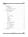
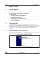
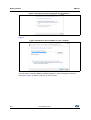
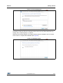
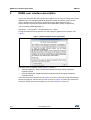
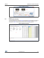
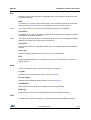
UM1747 User manual Getting started with STEVAL-IME002Vx graphical user interface Introduction This document describes the graphical user interface for the STEVAL-IME002Vx evaluation boards. There are two evaluation boards in the family: STEVAL-IME002V1 and STEVALIME002V2, designed to demonstrate the use of HM301D in multi-lead electrocardiogram (ECG) and single lead automated external defibrillator (AED) configurations respectively. The graphical user interface described here is called the EDEN application. Warning: These boards must be used in laboratories and development environments. This product must be never be connected to a human body. Figure 1. STEVAL-IME002Vx board December 2014 DocID026219 Rev 1 1/27 www.st.com Contents UM1747 Contents 1 2 Getting started . . . . . . . . . . . . . . . . . . . . . . . . . . . . . . . . . . . . . . . . . . . . . . 3 1.1 Package contents . . . . . . . . . . . . . . . . . . . . . . . . . . . . . . . . . . . . . . . . . . . . 3 1.2 EDEN installation . . . . . . . . . . . . . . . . . . . . . . . . . . . . . . . . . . . . . . . . . . . . 3 1.3 STEVAL-IME002Vx driver installation . . . . . . . . . . . . . . . . . . . . . . . . . . . . 3 EDEN user interface description . . . . . . . . . . . . . . . . . . . . . . . . . . . . . . . 6 2.1 EDEN main window . . . . . . . . . . . . . . . . . . . . . . . . . . . . . . . . . . . . . . . . . . 7 2.1.1 EDEN Menu . . . . . . . . . . . . . . . . . . . . . . . . . . . . . . . . . . . . . . . . . . . . . . . 8 File . . . . . . . . . . . . . . . . . . . . . . . . . . . . . . . . . . . . . . . . . . . . . . . . . . . . . . . . . . . . . . 9 View . . . . . . . . . . . . . . . . . . . . . . . . . . . . . . . . . . . . . . . . . . . . . . . . . . . . . . . . . . . . . 9 Tool . . . . . . . . . . . . . . . . . . . . . . . . . . . . . . . . . . . . . . . . . . . . . . . . . . . . . . . . . . . . . 9 Help . . . . . . . . . . . . . . . . . . . . . . . . . . . . . . . . . . . . . . . . . . . . . . . . . . . . . . . . . . . . 10 2.1.2 EDEN Toolbar . . . . . . . . . . . . . . . . . . . . . . . . . . . . . . . . . . . . . . . . . . . . 11 2.1.3 Board configuration . . . . . . . . . . . . . . . . . . . . . . . . . . . . . . . . . . . . . . . . 11 General tab . . . . . . . . . . . . . . . . . . . . . . . . . . . . . . . . . . . . . . . . . . . . . . . . . . . . . . 12 Input tab . . . . . . . . . . . . . . . . . . . . . . . . . . . . . . . . . . . . . . . . . . . . . . . . . . . . . . . . . 13 Channels tab . . . . . . . . . . . . . . . . . . . . . . . . . . . . . . . . . . . . . . . . . . . . . . . . . . . . . 14 Contact check tab . . . . . . . . . . . . . . . . . . . . . . . . . . . . . . . . . . . . . . . . . . . . . . . . . 16 Drivers tab . . . . . . . . . . . . . . . . . . . . . . . . . . . . . . . . . . . . . . . . . . . . . . . . . . . . . . . 17 Impedance tab . . . . . . . . . . . . . . . . . . . . . . . . . . . . . . . . . . . . . . . . . . . . . . . . . . . . 17 GPIOs tab . . . . . . . . . . . . . . . . . . . . . . . . . . . . . . . . . . . . . . . . . . . . . . . . . . . . . . . 18 2.2 2.3 3 2/27 2.1.4 Plot selection window . . . . . . . . . . . . . . . . . . . . . . . . . . . . . . . . . . . . . . 19 2.1.5 HM301D Register window . . . . . . . . . . . . . . . . . . . . . . . . . . . . . . . . . . . 20 EDEN plot window . . . . . . . . . . . . . . . . . . . . . . . . . . . . . . . . . . . . . . . . . . 22 2.2.1 Toolbar in the plot window . . . . . . . . . . . . . . . . . . . . . . . . . . . . . . . . . . . 23 2.2.2 Plot section window . . . . . . . . . . . . . . . . . . . . . . . . . . . . . . . . . . . . . . . . 24 2.2.3 Output flags . . . . . . . . . . . . . . . . . . . . . . . . . . . . . . . . . . . . . . . . . . . . . . 24 2.2.4 Impedance section . . . . . . . . . . . . . . . . . . . . . . . . . . . . . . . . . . . . . . . . . 24 EDEN data logging window . . . . . . . . . . . . . . . . . . . . . . . . . . . . . . . . . . . 25 Revision history . . . . . . . . . . . . . . . . . . . . . . . . . . . . . . . . . . . . . . . . . . . 26 DocID026219 Rev 1 UM1747 Getting started 1 Getting started 1.1 Package contents After installation, the following items are found in the “Program Files” subfolder: \STMicroelectronics\Eden application (the exact folder name may be different on your computer) This folder contains: 1.2 • The Eden.exe application and associated files. • A subfolder with the STEVAL-IME002Vx board drivers for 32- or 64-bit Windows OS (x86 and x64 folders respectively). • The STM32F103 firmware package subfolder. • The Restrib subfolder with a Software Development Kit for advanced users to write their own PC applications. EDEN installation Run EDEN_Application_1.x.y_date.exe: the setup Wizard guides you through the installation of the EDEN application, the USB virtual com device drivers and the Firmware Package source code on your computer. Once installation has completed successfully, click the “Finish” button. You can then explore the full package contents (described in Section 1.1). 1.3 STEVAL-IME002Vx driver installation As soon as the STEVAL-IME00Vx board is connected to a USB port on your PC, the “found new hardware wizard” starts, see Figure 2. Click the “Next” button. Figure 2. device driver installation wizard Select “Browse my computer for driver software” as shown in Figure 3. DocID026219 Rev 1 3/27 27 Getting started UM1747 Figure 3. How do you want to search for driver software? On next page, select “Let me pick from a list of device drivers on my computer” as per Figure 4. Figure 4. Browse for driver software on your computer If you followed the steps in Section 1.2, you will already have the board driver installed on your PC and the “STEVAL-IME002Vx ADAMO Platform” driver will appear in the list of drivers (see Figure 5). Select it and click on “Next” button. 4/27 DocID026219 Rev 1 UM1747 Getting started Figure 5. Driver selection list The PC will automatically select the correct INF file. Before installing the driver, Windows will display a Warning dialog box indicating that the driver has not passed Windows logo testing, click “continue anyway” to continue. Windows will eventually display a message indicating that the installation was successful. Click “Finish” to complete the installation (see Figure 6). Figure 6. Installation finish DocID026219 Rev 1 5/27 27 EDEN user interface description 2 UM1747 EDEN user interface description This section describes the user interface and explains how to use it to manage the STEVALIME002Vx and the embedded HM301D (diagnostic quality acquisition system for bioelectric sensors and bio-impedance measurements) to demonstrate the use in electrocardiogram (ECG) and automated external defibrillator (AED) configurations. You can find the EDEN application in: Start Menu -> All Programs -> STMicroelectronics -> Eden Accept the software license agreement to start using the graphical user interface, see Figure 7. Figure 7. EDEN software license agreement Select the correct evaluation board (Figure 8, Control 1): • STEVAL-IME002V1, Multi lead electrocardiogram (ECG) and body impedance evaluation board • STEVAL-IME002V2, Single lead electrocardiogram (ECG) and body impedance evaluation board Then select the serial port from the list (Figure 8, Control 2); the GUI usually automatically selects the right port, but the user can click on the icon (Figure 8, Control 3) to refresh the serial port. Finally, proceed by clicking the “Ok” button (Figure 8, Control 4). 6/27 DocID026219 Rev 1 UM1747 EDEN user interface description Figure 8. EDEN kit selector 2.1 EDEN main window The EDEN graphical user interface (Figure 9) has a simple and robust design, so you do not need any special training to use it. The circled numbers in Figure 9 correspond with the descriptions in Table 1 for the different control areas in the EDEN Application. Figure 9. EDEN main window DocID026219 Rev 1 7/27 27 EDEN user interface description UM1747 Table 1. EDEN main window description Control 2.1.1 Description 1 Menu bar 2 Toolbar 3 Board configuration setting section 4 Plot selection window 5 HM301D register window 6 Message log window EDEN Menu This is where you can access the various menu items. Some of the commands accessible from this location have a shortcut in the Toolbar. The structure of the main menu is: • • • File – New – Load CFG… – Save CFG… – Save Log… – Exit View – Log bar – Device setting – Plot window – Data log Tool – Link sensor values – Read all registers – Write all registers – Write and verify registers – Communication – Connect – Trace – Firmware upgrade… • 8/27 Help – Contents – About – Register list help DocID026219 Rev 1 UM1747 EDEN user interface description File Provides access to open and save configuration files. These options are similar to other document programs. New This allows you to create a new, default project. This command re-opens the kit selector dialog box (see Figure 8) to select a new board type or a new connection port. Note: This command does not restore the default register settings of the HM301D. Load CFG… This allows you to open an existing configuration file containing a set of register values for the HM301D mounted on the board. Note: The register values are not written to the HM301D devices. In fact, the HM301D Register Window shows dark pink colored cells to indicate this. Save CFG… This command saves a configuration file with the current register values and workspace settings. Save Log… Saves the logged messages (control 6 in Figure 9) to a specified file. Exit Exits the EDEN application. You will be prompted to save your changes if you have not already done so. View These commands change the way the workspace is presented. Log Bar Hides/shows the message log window, control 6 in Figure 9. Device setting Hides/shows the HM301D register window, control 5 in Figure 9. Plot Window When the board is connected, this command shows the plot window. Data Log When board is connected, this command shows the device data log window. Tool Contains a set of basic commands to communicate with STEVAL-IME002Vx boards. DocID026219 Rev 1 9/27 27 EDEN user interface description UM1747 Link sensors value Lock/Unlock the configuration value for each HM301D; this facilitates setting identical register values in the different HM301Ds on the board. Read all registers Reads all the HM301D registers and updates the HM301D register window (control 5 in Figure 9) with these values. Write all registers Writes the data in HM301D register window to all the HM301D registers. Write and verify registers Writes to all HM301D registers and subsequently reads them back to check the value of all the writable registers. Communication • Connect. Connect/disconnect the board from the application. • Trace. Shows a log message dialog with the message returned by the STM32 microcontroller on the board (this features has to be operated by the firmware). • Firmware upgrade... Allows the user to upgrade the firmware from a binary file (.hex). Help Provides quick access to help documentation, information about the authors and the board firmware version. Contents Shows the online help for the EDEN application About Shows a dialog box with information about the connected board, including the firmware version. Register list help Shows a dialog with the description of all registers and their fields. 10/27 DocID026219 Rev 1 UM1747 2.1.2 EDEN user interface description EDEN Toolbar The Toolbar provides shortcuts to the most common EDEN Menu commands, see Figure 10. From left to right, the icons represent: • File -> New • Tool -> Link sensor values • Tool -> Read all registers • Tool -> Write all registers • Tool -> Write and verify all registers • View -> Show plot window • View -> Data log window Figure 10. EDEN Toolbar For further information on these commands, please refer to Section 2.1.1 2.1.3 Board configuration Board configuration is the core section of the graphical user interface; it permits you to set all the features of the STEVAL-IME002Vx board and to set the parameters of the HM301Ds on it. For further details on the HM301D settings, refer to the relevant datasheet on www.st.com. The settings are arranged in different tabs: • General • Input • Channels • Contact checks • Drivers • Impedance • GPIOs • Each tab is detailed in the following sub-sections DocID026219 Rev 1 11/27 27 EDEN user interface description UM1747 General tab This tab offers the basic settings for the STEVAL-IME002Vx board, see Figure 11. • Number of devices: you can choose to use one, two or all the three HM301D devices on the board (not applicable for the STEVAL-IME002V2 board). • Clock selection: in order to enable a chain of three HM301Ds, you can choose how to propagate the clock from the master to the slave devices; there are three options: • – Ring oscillator; the propagated clock is generated by the internal oscillator of the master HM301D. – XTAL oscillator; the propagated clock is dictated by the external quartz (Q1) on the board. – External clock; the propagated clock is generated by an external clock via the CKEXT test pin. Common mode voltage: You can select the instrumentation amplifier common mode voltage between – 0.7 V – 1V • VREF: select the internal or external voltage reference. • Clock Output: enable or disable the clock output from the HM301D master; this option can only be edited on the STEVAL-IME002V2. • Analog HC buffer: enable the differential to single-ended block of ALL health channels. In this way the analog signal is available at the pins ANAx_OUT (x=[1,2 or 3]) of the HM301D. You can identify these analog pins on the board by the notation indicated in Table 2. The output voltage of the differential to single-ended block equals: V INxP − V INxN + V REF 2 where VREF is 0.8V. DIFF 2 SE _ OUT = Figure 11. General tab 12/27 DocID026219 Rev 1 UM1747 EDEN user interface description Table 2. HM301D channels analog output and how to identify on the board Silk screen label Description A01 HM301D Master: channel 1 single ended analog output A11 HM301D Master: channel 2 single ended analog output A21 HM301D Master: channel 3 single ended analog output A02 HM301D first Slave: channel 1 single ended analog output A12 HM301D first Slave: channel 2 single ended analog output A22 HM301D first Slave: channel 3 single ended analog output A03 HM301D second Slave: channel 1 single ended analog output A13 HM301D second Slave: channel 2 single ended analog output A23 HM301D second Slave: channel 3 single ended analog output Input tab This panel (see Figure 12) allows the user to: • configure the front-end MUX for each channel by connecting input pads INxy (x=1,2,3 y=P/N) with health channel inputs. • connect input AVG buffer[1,2,3] to any of the 6 input pads INxy (x=1,2,3 y=P/N). • connect the RLD output to any of the inputs pads INxy (x=1,2,3; y=P/N). Figure 12. Input tab DocID026219 Rev 1 13/27 27 EDEN user interface description UM1747 Figure 13. AVG buffers Figure 12 shows an example in which only the AVG buffers produce the average value of IN1P, IN2N and IN3N. The output of the AVG buffers is fed to the shield driver and RLD driver. Through the RLD output control, we can disconnect the input of the RLD driver from the output of the AVG buffers and connect it to any of the input pads INxN/P (for x=1,2,3). Channels tab This panel (see Figure 14) allows the user to set up all the parameters of the bio potential channels (see Figure 15); each channel can be switched on or off. The user can: 14/27 • Enable/disable digital filtering. • Set the PGA and INA gain, their respective values can be: 4, 2, 4/3, 1 and 16, 8 to obtain a final gain between 8 and 64. • Enable the healthcare channels. • Set the HPF and LPF cutoff frequency for both the ECG (HRLB) and pace maker (LRHB) channels. The HPF is only available when Recovery Mode is ON, while the LPF for LRHB is only available with one HM301D. All the available values are described in Table 3. • Set the fast recovery mode parameters. The first parameter is the overflow mask Time to select the blanking time for overflow detection (in the range 2.5 ÷ 37.5 ms or OFF). The other two parameters select the switching time for the first and second cutoff frequencies (200 ms ÷ 1 s). • For each healthcare channel, the digital HPF and analog HPF is available when the overflow mask time is OFF. In this case, the user can select the digital and analog HP cutoff frequency for HCx (x= 1, 2 or 3). • LRHB threshold (0-511); you can select the pacemaker detection threshold by inserting a value in the range 0 ÷ 511. The effects of this setting can be appreciated in the plot window by checking Ux_PMDy (for x=1,2,3 and y=1,2). DocID026219 Rev 1 UM1747 EDEN user interface description Figure 14. Channel tab Figure 15. Bio potential channel block schematic Table 3. HPF and LPF setting for ECG (HRLB) and pace maker (LRHB) channels High pass filter Low pass filter HRLB LRHB HRLB LRHB 0.05 Hz 0.05 Hz 0.1 Hz 0.7 Hz 37.5 Hz 10 kHz 0.5 Hz 1 Hz 50 Hz 0.7 Hz 5 Hz 75 Hz 1 Hz 1 kHz 100 Hz 2 Hz 150 Hz 5 Hz 200 Hz 300 Hz 600 Hz DocID026219 Rev 1 15/27 27 EDEN user interface description UM1747 Contact check tab This panel is organized in two sub-tabs: one dedicated to DC contact checks (see Figure 16) and the other dedicated to AC contact checks (Figure 17). In the DC contact checks tab, the user can: • Disable P-Side and N-Side checks for all the INxy input pads (x=1,2,3 y=P/N) of each HM301D mounted on the board. • Select the current (25 / 50 / 100 / 200 nA) of each contact check connected to INxy input pads (x=1,2,3 y=P/N). Figure 16. Contact checks DC tab In the AC contact checks tab, the user can: • Enable or disable the health channel x (x=1,2 or 3) current injection. • Select the current injection frequency (2.5 kHz or 5 kHz) for all the health channels of each HM301D. • Select the current injection value (5 uA, 10 uA or 20 uA) to provide to all health channels. • Reverse the phase of the injection frequency of the health channels. This is used in unipolar measurements. Figure 17. Contact checks AC tab 16/27 DocID026219 Rev 1 UM1747 EDEN user interface description Drivers tab This panel (see Figure 18 has all the setting related to the driver section of the HM301D, see also Figure 13 for reference. It allows the user to: • Select the number of AVG buffers to be used in the system (0 ÷ 15). • Enable or disable the single AVG buffers. • Enable or disable the WCT (wilson common terminal). • Enable or disable the shield driver. • Enable or disable the right leg driver (RLD). • Select the voltage reference for RLD buffer (0.7 V, 1 V or 1.49 V). • Open or close the RLD Loop. Figure 18. Drivers tab Impedance tab This panel (see Figure 19) collects all the settings related to the impedance channel; it only acts on the first HM301D. The user can: • Enable or disable the impedance channel. • Select the PGA and INA gain for the impedance channel, their respective values can be: 4, 2, 4/3, 1 and 16, 8 in order to obtain a final gain between 8 and 64. • Select the cutoff frequency of the digital LPF (1 and 20 Hz). • Enable the impedance current injection (CIP and CIN current generators). • Select the value of the current injection (5 uA, 10 uA or 20 uA). DocID026219 Rev 1 17/27 27 EDEN user interface description UM1747 Figure 19. Impedance tab GPIOs tab This panel (see Figure 20) allows the user to capture the HM301D signals on DGIO pins. It is possible to capture: • pm_rsh: data refresh of the LRHB signal path inside the HM301D. • clk: oscillator output. • PMD1 and PMD2: the output of the signal amplitude detection of the LRHB signal. • adc_pdmx (for x=1 or 2): first or second bit of the ΔΣ stream of the ADC of the impedance channel. • fchop: chopping signal for the input amplifiers and the signal for the AC contact check current injection. • por: power on reset signal. • ecg_rsh: data refresh of the HRLB signal path inside the HM301D. • z_rsh: data refresh of the impedance channel. • prefilt_rsh: data refresh of the pre-filtered signals. • out_flag_x (for x= 1..6): contact check flags go high when the comparator threshold is crossed. • hcx_overflow_o (for x=1, 2 or 3): overflow signals of the three acquisition channels. • imp_overflow_o: overflow signals of the impedance channel. For further details, please refer to the HM301D datasheet. Note: 18/27 The DIGIO1 of the first HM301D is fixed to pm_rsh to synchronize the STM32 readings. DocID026219 Rev 1 UM1747 EDEN user interface description Figure 20. GPIOs tab 2.1.4 Plot selection window This is where the user can select what to show in the Plot Window. For each HM301D device (named U1, U2 and U3), it is possible to select (see Figure 21): • the bio-potential channels (CHy with y=1, 2 or 3); • the LRHB channels (LRHB1 and LRHB2); • the elaborate HRLB channels (CH1_2, CH2_3 and CH3_1): • the pacemaker detection signals (PMD1 and PMD2); • the average value and modulated impedance channel outputs as real and imaginary parts. The user can also edit the Label for each plot simply by double clicking the label rectangle. DocID026219 Rev 1 19/27 27 EDEN user interface description UM1747 Figure 21. Plot selection It is recommended to not select more than 7-8 plots (depends on PC CPU speed and available memory) because each channel generates significant quantities of data. 2.1.5 HM301D Register window This section shows the values of all the internal registers of the HM301D mounted on STEVAL-IME002Vx boards; see Figure 22 and refer to the HM301D datasheet for further information. This is a read-only area reflecting all the modifications made to the board configuration settings. For each register, the user can find: 20/27 • the address of the register • its default value • the actual value; it is shown in dark pink when it is not yet written in the HM301D registers DocID026219 Rev 1 UM1747 EDEN user interface description Figure 22. Register window By double clicking on a single register label, it is possible see the register bit values (see Figure 23) with all the related details. Please refer to the HM301D datasheet for further information. DocID026219 Rev 1 21/27 27 EDEN user interface description UM1747 Figure 23. Example of register description 2.2 EDEN plot window By clicking on the relative icon on the taskbar (see Figure 10), the Plot Window appears (see Figure 24). The numbers in Figure 24 refer to the descriptions in Table 4, which lists the available control sections in this window. 22/27 DocID026219 Rev 1 UM1747 EDEN user interface description Figure 24. EDEN plot window Table 4. plot window parts 2.2.1 Control Description 1 Toolbar 2 Plot section 3 Output flag section 4 Impedance section Toolbar in the plot window Through this toolbar the user can: • save all the logged data (see Section 2.3) • copy the image to the clipboard • copy data to the clipboard • clear the plot • show or hide the cursors (the cursors function as they would in a traditional oscilloscope); the user can manipulate them to study the X and Y values • zoom the channel data to fit in the graphical window • follow channel tracking, this option can be used when trace plot mode is enabled • enable or disable a 50 or 60 Hz filter on acquired data • start or stop data acquisition from the board DocID026219 Rev 1 23/27 27 EDEN user interface description 2.2.2 UM1747 Plot section window Here the user can view plots of the data acquired by the HM301Ds for parameters chosen in the plot selection window (see Figure 21). The user can manipulate the plot by: 2.2.3 • Zooming the single axis in and out via the left mouse button and the Ctrl button simultaneously. • Moving the cursors left and right. • Changing other settings (line width, color, …) in the context menu. Output flags Certain HM301D events during operation are signaled by onscreen LEDs on the Plot Window which change from green to red when events occur. Up to thirty-six different events can be captured by the HM301Ds; for further details see Table 5 and the HM301D datasheet. Table 5. Output flags Label U1 U2 U3 Description INxP DC * * DC contact check for the specific input INxN DC * * DC contact check for the specific input CHx * * Channel overflow Impedance * * Impedance channel overflow Over Curr N * * Over current on N input Over Curr P * * Over current on P input Note: * Available only on STEVAL-IME002V1. 2.2.4 Impedance section The impedance channel of HM301D is used to measure the impedance of the body and measure its variation due to respiration. It is important remember that the HM301D mounted on the STEVAL-IME002Vx board also measures the in-series resistance created by the protection mechanisms and the board itself. It is therefore advisable to use the CIN and CIP test points on the board to evaluate the level of impedance. The operation of the impedance section is linked to the impedance tab (see Figure 19), as the user has to enable the impedance channel through this tab. The user can easily set the offset and the reference of the impedance formula by adding some nominal resistances to the board connector and inserting the relative value in the text box of the dialog box. 24/27 DocID026219 Rev 1 UM1747 2.3 EDEN user interface description EDEN data logging window In order to permit users to save the acquired data for post-processing and elaboration in other software environments (i.e., Mathworks Matlab), all the selected data can be saved through the data log window in the toolbar (see Figure 9 and Figure 10). Once the dialog box appears (see Figure 25), the user can: • Save the logged data; a filename prompt appears. • Clear all the logged data. • Start and stop the data acquisition; this is an alternative to the plot function in order to avoid overloading the PC during this phase. • Add the contact check values to the saved data (see HM301D datasheet for further details). • Save the data in HEX format instead of adl (Adamo devices data log), which is an ASCII format file. Figure 25. EDEN data logging window Example: In order to export the AC_I and AC_Q data, the user selects these two components in the plot selection window (Figure 21) and then clicks on data log window icon (Figure 10); the data logging window will appear as in Figure 25. The user then begins acquisition by clicking on the start button. DocID026219 Rev 1 25/27 27 Revision history 3 UM1747 Revision history Table 6. Document revision history 26/27 Date Revision 09-Dec-2014 1 Changes Initial release. DocID026219 Rev 1 UM1747 IMPORTANT NOTICE – PLEASE READ CAREFULLY STMicroelectronics NV and its subsidiaries (“ST”) reserve the right to make changes, corrections, enhancements, modifications, and improvements to ST products and/or to this document at any time without notice. Purchasers should obtain the latest relevant information on ST products before placing orders. ST products are sold pursuant to ST’s terms and conditions of sale in place at the time of order acknowledgement. Purchasers are solely responsible for the choice, selection, and use of ST products and ST assumes no liability for application assistance or the design of Purchasers’ products. No license, express or implied, to any intellectual property right is granted by ST herein. Resale of ST products with provisions different from the information set forth herein shall void any warranty granted by ST for such product. ST and the ST logo are trademarks of ST. All other product or service names are the property of their respective owners. Information in this document supersedes and replaces information previously supplied in any prior versions of this document. © 2014 STMicroelectronics – All rights reserved DocID026219 Rev 1 27/27 27