1
McQuw@
—
Operation
Manual
Bulletin No. OM 123
September,
1994
F’arl No. 579083Y
MicroTech@
Self-contained Air Conditioning Unit Controller:
VAV or CAV-DTC Control
Used With McG)uay Models SWP, SWT and SCP Units
Table of Contents
Introduction
. . . . . . . . . . . . . . . . . . . . . . . . . . . . . . . ...3
SoftwareID . . . . . . . . . . . . . . . . . . . . . . . . . . . . . . . . ...4
Getting
Started . . . . . . . . . . . . . . . . . . . . . . . . . . . . ...4
UsingtheKeypad/Display
..
Menu Structure . . . . . .
Display Format . . . . . .
Password Protection . .
Keypad Functions . . . .
Keypad/DisplayExercises
.
.
.
.
.
.
.
.
.
.
VAVand CAV-SAT Menu Tables
Status Menus . . . . . . . . .
Control Menus . . . . . . . .
Alarm Menus . . . . . . . . .
Operator’s
Guide
.
.
.
.
.
.
.
.
.
.
.
.
.
.
.
.
.
.
.
.
.
.
.
.
.
.
.
.
.
.
..
..
..
.,
..
..
.
.
.
.
.
.
.
.
.
.
.
.
.
.
.
.
.
.
..
..
..
..
..
..
.
.
.
.
.
.
.
.
.
.
.
.
..
..
..
..
..
..
.
.
.
.
.
.
.
.
.
.
.
.
.
.
.
.
.
.
.
.
.
.
.
.
.
.
.
.
.
.
.
.
.
.
.
.
.
.
.
.
.
.
.
.
.
.
.
.
.
.
.
.
.
.
.
.
. ...7
. ...7
...10
...14
. . . . . . . . . . . . . . . . . . . . . . . . . ...16
Determining
Unit Status . . . . . . . . . . . . .
. . . . . . . . . . . . . . . . . .
Cooling Status . . . . . . . . . . . . . . .
Heating Status . . . . . . . . . . . . . . .
Misc Status . . . . . . . . . . . . . . . . . .
Unit
.
.
.
.
...4
...5
...5
...5
...5
...6
StatUS
Auto/ManualOperation
Control Mode . . .
Service Mode . . .
Tenant Override .
Operator Override
Fast Timers . . . . .
.
.
.
.
.
.
.
.
.
.
.
.
.
.
.
.
.
.
.
.
.
.
.
.
.
.
.
.
.
.
.
.
.
.
.
.
.
.
.
.
.
.
...16
...16
...16
...17
...17
.
.
.
.
.
.
.
.
.
.
.
.
.
.
.
.
.
.
.
.
.
.
.
.
.
.
.
.
.
.
.
.
.
.
.
.
..
..
..
..
..
.,
.
.
.
.
.
.
.
.
.
.
.
.
.
.
.
.
.
.
.
.
.
.
.
.
.
.
.
.
.
.
.
.
.
.
.
.
.
.
.
.
.
.
.
.
.
.
.
.
...17
...17
...18
...18
...19
...19
Scheduling . . . . . . . . . . . . . . .
Setting Date anytime
.
Daily Scheduling . . . . . .
Holiday Scheduling . . . .
.
.
.
.
.
.
.
.
.
.
.
.
.
.
.
.
.
.
.
.
.
.
.
.
.
.
.
.
.
.
.
.
.
.
.
.
.
.
.
.
.
.
.
.
.
.
.
.
.
.
.
.
.
.
.
.
.
.
.
.
.
.
.
.
...19
...19
...19
...20
Alarm Monitoring, . . . . . .
About Alarms . . . .
Displaying Alarms .
Clearing Alarms . .
SettingAlarm
Limits
.
.
.
.
.
.
.
.
.
.
.
.
.
.
.
.
.
.
.
.
.
.
.
.
.
.
.
.
.
.
.
.
.
.
.
.
.
.
.
.
.
.
.
.
.
.
.
.
.
.
.
.
.
.
.
.
.
.
.
.
.
.
.
.
.
.
.
.
.
.
.
.
.
.
.
.
.
.
.
.
...20
...20
...21
...22
...22
.
.
.
.
.
.
.
.
.
.
.
.
.
.
.
.
.
.
.
.
.
.
.
.
.
.
.
.
.
.
.
.
.
.
.
.
.
.
.
.
.
.
.
.
.
.
.
100% Outside Air Units . . . . . . . . . . . . . . . . . . . . . ...29
Cooling: Multistage . . . . . . . . . .
Temperature Control . . . .
Low EWTCooling Lockout
Setpoint Reset . . . . . . . .
...
...
..
...
.
.
.
.
.
.
.
.
.
.
.
.
.
.
.
.
.
.
.
.
.
.
.
.
.
.
.
.
.
.
.
.
.
.
.
.
.
.
.
.
.
.
.
.
.
.
.
.
...29
...29
...31
...31
Air Modulation,
. . . . . . . . . . . . . . . . . . . . . . . . . . . ...33
Dual Motor . . . . . . . . . . . . . . . . . . . . . . . . . . ...33
VIV/lnverters . . . . . . . . . . . . . . . . . . . . . . . . . ...33
Cooling: Modulating (SCP units only). . .
Temperature Control . . . . . . . . . . .
LowAmbient Cooling Lockout . . . .
Setpoint Reset . . . . . . . . . . . . . . .
.
.
.
.
.
.
.
.
.
.
.
.
.
.
.
.
.
.
.
.
.
.
.
.
.
.
.
.
.
.
.
.
...34
...34
...34
...34
Heating: Multistage . . . . . . . . . . . . .
Temperature Control . . . . . . . .
High Ambient Heating Lockout
Morning Warm-up Control . . . .
DischargeAir Low Limit Control
.
.
.
.
.
.
.
.
.
.
.
.
.
.
.
.
.
.
.
.
.
.
.
.
.
.
.
.
.
.
.
.
.
.
.
.
.
.
.
.
.
.
.
.
.
.
.
.
.
.
.
.
.
.
...35
...35
...35
...35
...36
Heating: Modulating . . . . . . . . . . . . .
Temperature Control . . . . . . . .
High Ambient Heating Lockout
Morning Warm-up Control . . . .
DischargeAir Low Limit Control
.
.
.
.
.
.
.
.
.
.
.
.
.
.
.
.
.
.
.
.
.
.
.
.
.
.
.
.
.
.
.
.
.
.
.
.
.
.
.
.
.
.
.
.
.
.
.
.
.
.
.
.
.
.
...36
...36
...37
...37
...37
Heating Control for Units with SATControl
Staged Heating Control . . . . . . . . .
Modulating Hot Water Control . . . .
Temperature Control . . . . . . . . . . .
High Ambient Heating Lockout . . .
Setpoint Reset . . . . . . . . . . . . . . .
Morning Warm-Up Control . . . . . . .
DischargeAir Low Limit Control . .
.
.
.
.
.
.
.
.
.
.
.
.
.
.
.
.
.
.
.
.
.
.
.
.
.
.
.
.
.
.
.
.
.
.
.
.
.
.
.
.
.
.
.
.
.
.
.
.
.
.
.
.
.
.
.
.
.
.
.
.
.
.
.
...38
...38
...38
...38
...39
...39
...40
...40
Supply Fan Airflow . . . . . . . .
Static Pressure Control
Setpoint Reset . . . . . .
Post Heat (VIVOnly) . .
.
.
.
.
.
.
.
.
.
.
.
.
.
.
.
.
.
.
.
.
.
.
.
.
.
.
.
.
.
.
.
.
...41
...41
...41
...41
.
.
.
.
.
.
.
.
.
.
.
.
.
.
.
.
.
.
.
.
.
.
.
.
.
.
.
.
.
.
.
.
.
.
.
.
. . . . . . . . . . . . . . . . . . . ...23
Unoccupied Control . . . . . . . . . . . . . . . . . . . . . . . . ...41
Heating (Night Setback) . . . . . . . . . . . . . . . . ...41
Cooling (Night Setup) . . . . . . . . . . . . . . . . . . ...42
Operating States and Sequences. . . . . . . . . . . . . . ...23
Operating State Descriptions. . . . . . . . . . . . . ...24
Sequence Charts . . . . . . . . . . . . . . . . . . . . . ...25
Head Pressure Control . . . . . . . . . . . . . . . . . . . . . . ...42
Description
of Operation
Start-up Control . . . . . . . . . . . . . . . . . . . . . . .
Before Start-up . . . . . . . ...”....
.....
Fan Start-up Mixed or 100% Return Air.
Fan Start-up lOO% Outside Air.....
..
.
.
.
.
.
.
.
.
.
.
.
.
.
.
.
.
...26
...26
...26
...26
Heat/CoolChangeover
. . . . . . . . . . . . . . . . . . . . . . ...26
Temperature Control . . . . . . . . . . . . . . . . . . . ...26
Economizer . . . . . . . . . . . . . . . . . . . . . . .
Temperature Control . . . . . . . . . . . .
Changeover Method Waterside . . . .
Changeover MethodAirside
......
Transition Economizer to Mechanical
.
.
.
.
......
......
......
......
Cooling
...27
...27
...28
...28
. ..29
Bypask Valve . . . . . . . . . . . . . . . . . . . . . . . . . . . . . ...29
Building Static Pressure Control . . . . . . . . . . . . . . . ...42
Optimal Start . . . . . . . . . . . . . . . . . . . . . . . . . . . . . ...43
Dehumidification
Control
Alarm Control . . . . .
Faults . . . . . .
Problems . . .
Warnings . . .
.
.
.
.
MicroTech
Features
Control
.
.
.
.
.
.
.
.
. . . . . . . . . . . . . . . . . . . . ...43
.
.
.
.
.
.
.
.
.
.
.
.
.
.
.
.
.
.
.
.
.
.
.
.
.
.
.
.
.
.
.
.
.
.
.
.
.
.
.
.
.
.
.
.
.
.
.
.
.
.
.
.
.
.
.
.
.
.
.
.
.
.
.
.
.
.
.
.
.
.
.
.
.
.
.
.
.
.
.
.
...44
...44
...45
...46
. . . . . . . . . . . . . . . . . ...47
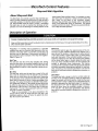
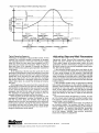
Step-and-WaitAlgorithm
. . . . . . . . . . . . . . . . . . . . . ...47
About Step-and-Wait . . . . . . . . . . . . . . . . . . . ...47
Description of Operation . . . . . . . . . . . . . . . . ...47
Adjusting Step-and-Wait Parameters . . . . . . . ...48
McQuay, MicroTech, and are registered trademarks of McQuay International.
Monitor and Open Protocol are trademarks of McQua y International.
@l 994 McQuay International
Page2/0M123
.
.
.
.
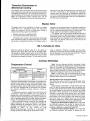
Introduction
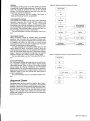
This manual provides information about the MicroTech@ control system used in the McQuay@ Self-contained
Air
Conditioning
product line. It specifically
describes the
sequences of operation and programmable options for units
with factory equipped variable air volume (VAV) equipment
and units with factory equipped constant air volume, discharge air temperature control (CAV-STC). It also includes
information on how to use the keypad/display to enter and
display data.
For information on MicroTech components, input/output
configurations,
field wiring options and requirements, and
I
I
Electric
shock
Can cause personal
injury
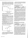
Table 1. Model-Specific
Literature
Self-contained
Model
Self-contained
unit Installation
Installation
& Maintenance
Data
Bulletin Number
SWP
or equipment
IM 550
I
damage.
This equipment must be properly grounded. Connections and service to the MicroTech control panel must be performed
only by personnel that are knowledgeable in the operation of the equipment being controlled.
Excessive
ation.
I
hazard.
service procedures, refer to Bulletin No. IM 608, MicroTech
Self-contained Air Conditioning Unit Controller. For installation and start-up instructions and general information on a
particular Self-contained
unit, refer to its model-specific
installation manual (see Table 1).
moisture
in the control
panel can cause hazardous
working
conditions
When servicing this equipment
tected from the rain.
during rainy weather, the electrical components
Extreme
Can cause damage
temperature
hazard.
to system
and improper
equipment
I
oper-
in the main control panel must be pro-
components.
I
This MicroTech controller is designed to operate in ambient temperatures from –20”F to 125”F. It can be stored in ambient temperatures from –40”F to 140”F. It is designed to be stored and operated in relative humidity up to 95%. (non-condensing).
I
I
Grossly
misadjusting
Step-and-Wait
parameters
can cause erratic
unit operation
and equipment
damage.
Step-and-Wait parameters should be adjusted only by trained personnel that have a thorough understanding
affect overall system operation.
of how they
I
I
.
.
This equipment generates, uses and can radiate radio frequency energy and, if not installed and used in accordance with
this instruction manual, may cause interference to radio communications.
It has been tested and found to comply with
the limits for a Class A digital device, pursuant to part 15 of the FCC rules. These limits are designed to provide reasonable protection against harmful interference when the equipment is operated in a commercial environment. Operation of
this equipment in a residential area is likely to cause harmful interference in which case the user will be required to correct the interference at his own expense. McQuay International
disclaims any liability resulting from any interference or for the correction
thereof.
OM 123/ Page 3
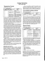
Software ID
MicroTech Self-contained
Air Conditioning
Unit controller
software is factory installed and tested in each unit prior to
shipment. The program loaded into the controller is identified
by its software part number (also referred to as the “ldent”).
This number is printed on the software ID tag, a small label
affixed to the control panel next to MCB1. For more information, refer to the “Software ID” section of Bulletin No. IM 608,
MicroTech Self-contained Air Conditioning Unit Controller.
The software part number is also encoded in the controller’s memory and is available for display on menu 25 of
the keypad/display
or a PC equipped
with MicroTech
MonitorTM software.
(For information
on using the
keypad/display, see the “Getting Started” portion of this manual.) Using menu 25 or Monitor software is the most reliable
way of determining the controller’s software part number.
Software part number codification is as follows:
950600
Q
Q
‘rogramnumber~~
I
Version (numeric)
Version revision (zero then alphabetical)
The standard software part number for the program used
to control Self-contained Air Conditioning unit is 950600020.
If the unit’s program number does not match this number, it
is likely that a special program has been loaded into the controller. In this case, some of the information in this manual
may not be applicable.
Note: The information in this manual should be applicable with software
version
revisions
following
“O” (ie
A, B,..etc.).
Getting Started
The MicroTech
Self-contained
Air Conditioning
Unit
Controller is a self-contained device that is capable of complete, stand-alone operation. It can also be included in a network with other unit and auxiliary controllers. Regardless of
whether the controller is stand-alone or part of a network,
you can display and modify information in the controller by
using any of the following three methods:
●
Using the keypad/display
panel
●
●
Using the keypad/display
in an optional Remote
Monitoring and Control (RMC) Panel
Using an optional PC equipped with Monitor software
The following “Getting Started sections describe how to
use the keypad/display. For information on using the optional Monitor software package, see the user’s manual supplied with the Monitor software.
in the unit’s main control
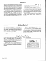
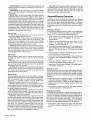
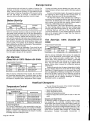
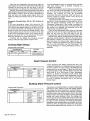
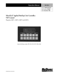
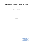
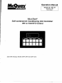
Using the Keypad/Display
The Kevpad/Dispav
Board, shown in Figure 1, is provided
with all” MicroTech’ Self-contained
Air ‘Conditioning
Unit
Controllers. With the keypad/display you can monitor operating conditions, system alarms, control parameters, and
schedules. After the password has been entered, you can
edit setpoints, parameters, and schedules.
The optional RMC Panel has a keypad/display that can
emulate the unit-mounted keypad/display. Once the RMC
Panel’s keypad/display is interfaced to the desired unit controller, it operates exactly the same as the unit-mounted keypad/display.
Page 4 / OM 123
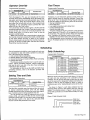
Figure 1. Keypad/Display
-
CATEGORY MENU ITEM
ACTION
BB
a
B
EB
.HB
IZl
.m
.BH
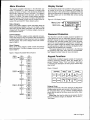
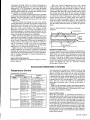
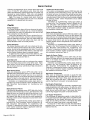
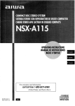
Menu Structure
Display Format
The keypad accessible information in the MicroTech controller is organized in a menu structure to provide quick
access. As shown in Figure 2, this structure is divided into
three levels: categories, menus, and items. The category,
which is the highest level in the structure, can be “Status,”
“Control,” or “Alarm.” The name of each category describes
the basic purpose of the menus it contains. Complete information on the contents of each menu is included in the following “VAV and CAV-DTC “Menu Tables” section.
The information stored in the controller’s menu structure can
be viewed on the 2-line by 16-character LCD display. As
shown in Figure 3, the current menu is displayed on the top
line and the current item is displayed on the bottom line. The
item line contains one or more fields that convey varying
information.
Status Category
Menus in the Status category contain information about the
current operating conditions in the unit. The fields in these
menu items provide status information only and cannot be
changed with the keypad. The Status category menus are
summarized in Table 2.
Control Category
Menus in the Control category contain setpoints and parameters that define how the unit operates. After the password
is entered, most fields in these menu items can be changed
with the keypad. The Control category menus are summarized in Table 3.
Alarm Category
Menus in the Alarm category contain current and previous
alarm information. The Alarm category menus are summarized in Table 4.
Figure 2. Keypad Accessible
Category
Menu
Menu Structure
Item
Item1
status
T-F=
{
Figure 3. LCD Display Format
‘;’’”;-
Password Protection
The MicroTech controller includes password protection to
guard against the entry of inadvertent changes. When you
attempt to change the value of an adjustable parameter with
the keypad, the controller prompts you to enter the password. If the correct password is entered, the controller will
allow you to make changes as desired. Fifteen minutes after
the last keystroke is made, the controller will disallow further
changes until the password is recentered.
The keypad password for all controllers is the following
key sequence: enter, enter, enter, enter. It is not adjustable.
See “Keypad Functions” below for more information.
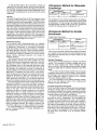
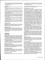
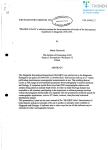
Keypad Functions
The MicroTech controller’s keypad consists of 12 pressure
sensitive membrane switches, which are divided into 4
groups: “Category,” “Menu,” “kern,” and “Action.” See Figure
4. Following are descriptions of these groups and the keys
they contain.
Figure 4. Keypad
CATEGORY
m
1-
.
.
‘ “arm
-F-m
5-F=
1-
==T==
ACTION
EIB El R Elm
EIH El El BB
Category Group
Acting like bookmarks in the menu structure, the keys in the
Category group provide quick access to the desired menus.
By using these keys, you can minimize scrolling between
menus with the keys in the Menu group (see below). Refer
to Figure 2.
Status Key: Any time the status key is pressed, the first
menu in the Status category is displayed. This is menu 1,
“Unit Status.”
OM 123/ Page 5
Control Key: Any time the control key is pressed, the first
menu in the Control category is displayed. This is menu 11,
“Control Mode.”
Alarms Key: Any time the alarms key is pressed, the first
menu in the Alarm category is displayed. This is menu 26,
“Curr Alarm.”
Switch Key: The switch key toggles the display between
associated Status and Control category menu items. It
allows you to quickly check a controlled condition (temperature, pressure, position) against its setpoint. For example, by
pressing switch when the duct static pressure is currently
being displayed (“Duct=” item under menu 5), the duct static pressure setpoint will be displayed (“Duct Spt=” item under
menu 17). If switch is pressed again, the actual pressure will
be displayed again. Note that the switch key will not work
with every menu item. Tables 3 and 4 list the switch key destinations for all applicable menu items.
Menu Group
The keys in the Menu group allow you to choose the menu
you want to display. Refer to Figure 2.
Prev Key: When the Menu prev key is pressed, the display will scroll to the previous menu in the structure. This
action will occur regardless of the current menu number.
Note that you can “wrap around from the first menu to the
last menu by pressing the Menu prev key twice.
Next Key: When the Menu next key is pressed, the display will scroll to the next menu in the structure. This action
will occur regardless of the current menu number. Note that
you can “wrap around” from the last menu to the first menu
by pressing the Menu next key twice.
Item Group
After you select a menu, you can choose the item you want
to display by using the keys in the Item group. Refer to
Figure 2.
Prev Key: When the Item prev key is pressed, the display
will scroll to the previous item in the current menu. Note that
you can “wrap around from the first item to the last item by
pressing the Item prev key twice.
Next Key: When the Item next key is pressed, the display
will scroll to the next item in the current menu. Note that you
can “wrap around” from the last item to the first item by
pressing the Item next key twice.
Action Group
The Action group keys allow you to clear alarms or change
setpoints and parameters in the selected item’s field(s). Note
that the password must be entered before any setpoint,
parameter,
or schedule
changes
can be made. See
“Password Protection” above for more information.
Incr Key: When the incr key is pressed, the entry in the
item’s selected field will change to the next higher value or
next available selection. The field being edited will flash until
the enter or clear key is pressed.
Deer Key: When the deer key is pressed, the entry in the
item’s selected field will change to the next lower value or
previous available selection. The field being edited will flash
until the enter or clear key is pressed.
Enter Key: When the enter key is pressed, the entry in
the item’s selected field will be locked in. If the selected item
has one field, pressing enter also completes the edit. If the
selected ”’item has’ more than one field, pressing enter also
makes the next field available for editing with the incr and
deer keys. if no change is desired, press enter until the
desired field is flashing or the edit is complete. (It is possible
to initiate an edit of a multi-field item by pressing the enter
key. In this instance, the first field would be left unchanged
and the second field would be available for editing.)
F‘age 6 / OM 123
Clear Key: The clear key is used to clear
ed (flashing) fields. When menu 26, ‘(Curr
display, pressing clear will clear the current
item field is being edited, pressing clear
field’s previous entry and end the edit.
Keypad/Display
alarms and editAlarm,” is in the
alarm. When an
will restore the
Exercises
Following are three exercises that will guide you through
some typical keypad operations. Note that often there is
more than one way to perform an operation. For example,
you can use the Menu group keys with or without the optional Category group keys to quickly find the menu you want to
display.
Changing a Setpoint
In this exercise, assume that the Cooling Control Dead Band
is 1“F. Using the following procedure, you will change this
setpoint to 2°F and thus enable mechanical cooling.
1. Press control in the Category key group. The first menu
of the Control category is displayed. This is menu 11,
“Control Mode.”
2. Press next in the Menu kev group twice. Menu 13, “Clg
Control,” is displayed. The- first item of this rnenu,
“Setpoint=,” is also displayed.
3. Press next in the Item key group once. The “Dead Band=”
item is displayed. This is the Cooling Control Dead Band
Setpoint. The default value of 1‘F should also be displayed.
4. Press either incr or deer in the Action key group. The controller prompts you for the password.
5. Press enter in the Action key group four times. (This is the
password.) The “Password Verified” message is displayed.
6. Press incr until the setpoint is 2°F. Notice
adjustable field flashes during the change.
that the
7. Press enter. The field stops flashing.. This means that the
new setpoint is locked in.’
Clearing an Alarm
In this exercise, assume that a “fault” alarm exists. This type
of alarm shuts down the unit and keeps it off until the alarm
is manually cleared. If the conditions that caused the alarm
are gone, you can clear a fault alarm by using the following
procedure.
1. Press alarms in the Category key group. The first menu
of the Alarm category is displayed. This is menu 26, “Curr
Alarm.” The first item of menu 26 is also displayed. It
probably shows “NO Active Alarms.” Assume that a fault
alarm exists.
2. Press clear in the Action key group. This clears the alarm
and returns the unit to normal operation.
Modifying a Schedule
In this exercise, assume that a change in building occupancy requires the self-contained unit to run from 12:30 a.m. to
5:00 p.m. on Saturday. Currently, the unit is scheduled to be
shut down on Saturday. Using the following procedure, you
will change this schedule accordingly.
(This procedure
assumes that the password has previously been entered
and the 15-minute authorization timer has not expired.)
1. Press alarms in the Category key group. The first menu
of the Alarm category is displayed. This is menu 26, “Curr
Alarm.”
2. Press prev in the Menu key group four times. Menu 22,
“Schedule,” is displayed. The first item of this menu,
“Override=, “ is also displayed. Note that you could have
started at the beginning of the Control category of menus
and stepped forward to menu 22 by using the next key,
but it would have taken longer,
3. Press prev in the Item key group three times. (This makes
use of the wrap-around capability.) Menu item “Sat,” is
displayed. The default start-stop schedule of 00:00-00:00
should also be displayed. Each of the four sets of zeros
is an adjustable field: start hour, start minute, stop hour,
and stop minute. Note that you could have stepped forward to “Sat” by using the next key, but it would have
taken longer.
4. Press enter in the Action key group. The second field
(start minute) flashes, indicating that it can be edited.
Since the desired schedule is 00:30–1 7:00, the first field
(start hour) does not need to be changed. By pressing
enter instead of incr, you can bypass this field.
5. Press incr until the start minute field is 30. Notice that the
adjustable field flashes during the change.
6. Press enter. The second field stops flashing, and the third
field (stop hour) starts flashing. This means that the new
start minute is locked in and the stop hour can be edited.
7. Press incr until the stop hour field is 17.
8. Press enter. The third field stops flashing,
field (stop minute) starts flashing.
and the fourth
9. Since the stop minute field does not require editing, press
enter again. The fourth field stops flashing, thus completing the edit. Note that the same result could have been
accomplished by pressing the clear key instead of the
enter key.
VAV and CAV-DTC Menu Tables
The following tables show every menu, item, and field in the
menu structure. These menus and items can all be displayed with the keypad/display. (Monitor software provides
many additional monitoring features and adjustable parameters.)
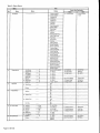
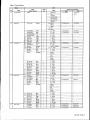
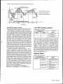
Status Menus
Table 2 lists all possible menus and items in the Status category. The table’s range column lists all possible values for
each item. Following are brief descriptions of the Status category menus.
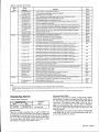
Unit Status
Menu 1, “Unit Status,” tells you which operating or special
state the unit is currently in. For more information, see the
“Determining Unit Status” section in the ‘(Operator’s Guide”
portion of this manual.
Temperatures
Menu 2, “Temperatures,” provides the current temperatures
at all connected sensor locations. Menu item ‘(Cntl Temp=,”
displays the current Control Temperature, which is the temperature at the selected representative zone sensor.
Waterflow
Menu 3, ‘(Waterflow,” tells you if waterflow
whether the pump is on or off.
is present and
Airflow Modulation
Menu 5, “Airflow Mod,” provides
motor control parameters.
the WV, inverter, or dual
Economizer
Menu 6 ‘(Economizer,” tells you the current economizer
tion and whether it is enabled or disabled.
posi-
Cooling Status
Menu 7, “Cool Status,” tells you which kinds of cooling, if
any, are currently allowed. If cooling is disabled, it tells you
why. For more information,
see the ‘(Determining
Unit
Status” section in the “Operator’s Guide” portion of this manual.
Heating Status
Menu 8, “Heat Status,” tells you whether heating is currently allowed. If heating is disabled, it tells you why. For more
information, see the “Determining Unit Status” section in the
“Operator’s Guide” portion of this manual.
Operating Hours
Menu 9 “Operating Hrs,” provides the operating hours for
each compressor, cooling, economizer, heating and override.
Miscellaneous
Status
Menu 10, “Mist Status,” tells you heat output, outdoor
damper position, head pressure, percent humidity and dewpoint temperature.
Fan/Airflow
Status
Menu 4, “Fan/Airflow,” tells you which fans are currently on
and whether there is airflow through the unit. Airflow status
is sensed by PC7, a differential pressure switch.
OM 123/ Page 7
Table 2. Status Menus
...-.
Mr.”,
No.
.“
,
I
Item
. .
Name
1
Switch Key Destination
Range
Name
Menu
11. Control Mode
Off-Unoccupied
Unit Status
Item
current control
mode
Ott Fan Switch
Off-Network
Off-Manual
Off-Service
Off -Alarm
Calibrate
Start Requested
Startup Initial
Recirculate
Fan On
Heating
Morning Warm Up
Fan On-Htg -Stg
Post Heat
Economizer
Cooling
Heating-Stage
MWUP Htg-Stg
Fan On- Heating
Cooling-Stage
Unoccupied
Heat
Unocc Htg-Stg
Unoccupied Cool
Unocc Clg-Stg
Unocc Economizer
Dehum-Fan On
Dehum-Heating
Dehum-Mwup
Heat
Dehum-Fan On Ht
Dehum-Post Heat
Dehum-Economizer
Dehum-Cooling
Temperatures
2
O
Waterflow
3
Cntl Temp=
—
“F
(Same as CT sensor)
12. Heat/Cool
Cntl Temp=
Supply Air=
—
“F
O – 255°F
13. Clg Control
Setpoint=
13. Clg Control
Min EWT=
Ent Water=
—
“F
O – 255°F
Lvg Water=
—
‘F
O – 255°F
Mixed Air=
—
‘F
O – 255°F
Space=
—
“F
0- 255°F
16. Unocc Htg/Clg
Cooling Spt=
Return Air=
—
“F
O-25YF
15. Alarm Limits
Hi Return=
Outdr Air=
—
“F
—100-
14, Htg Control
Max OAT=
@ Waterflow=
Fans/Airflow
—
No
—
On
off
Yes
Airflow.
—
No
@ Supply Fan=
_
@
_
Supply Fan=
15YF
Yes
_
Pump=
4
—
On
—
off
oft
Low
Hi
On
Fan OP.
5
6
@
AilflOWMod
@ Economizer
O
Velocity=
off
0-1675
FPM
@ Current=
—FpM
_Amps
0-30
@ Duct P=
—Wc
0-4.00
@ Bldg P=
-0.25-0.25
@ Vane Pos=
—Wc
_“/.
0-1 00%
O
Fan Speed=
—%
0-1 00%
Position
—
Econo=
%
17. Motor Control
Wc
17. Duct Pressure
Duct Spt=
17. Bldg Pressure
Zone Spt=
WC
o – 100%
@ 18. Economizer
Min Airilow=
Disabled
@ 18. Economizer
Enthalpy=
Enabled
Page 8 / OM 123
Amp Limit=
Amps
Table 2. Status Menus (cent’d)
Menu
Item
Name
Name
-7
I
Switch Key Destination
Range
Menu
Off - No
Item
I
—
Off-Unoccupied
Cool Status
Flow
Off - Temperature
Network Disable
—
Switch Disable
—
Manual Disable
Off -Alerm
—
No Cooling Avail
—
Compressors
Only
–
—
Economizer Only
—
All Clg Allowed
7
—
Off-OAT Lockout
Heat Status
Off-Unoccupied
Network Disable
1-
Switch Disable
Manual Disable
I
1-
1
—
—
Off-Alarm
Heating Allowed
7
7
Operating
Hrs =
0-50,000
Hrs
Fan
0-50,000
Hrs
!3 Lo Spd Fan
0-50,000
Hrs
3
Fan=
3
HiSpd
1
Comp #l=
0-50,000
Hrs
1
Comp #2=
0-50,000
Hrs
1
Comp #3=
0-50,000
Hrs
1
Comp #4.
0-50,000
Hrs
)
Comp #5=
0-50,000
Hrs
1
Comp #6=
0-50,000
Hrs
3
Cooling=
_
0-50,000
Hrs
@ Econo=
0-50,000
Hrs
1
Heating=
0-50,000
Hrs
Override=
0-50,000
Hrs
Heat Output=
Mist Status
—
—
—
—
Heat
_
cool
Outdr Dmpr=
Close
_
—
Open
)
Head Pres.
_
0-255
PSI
19. Head Pressure
Setpoint=
)
Humidity=
—%
o –loo
%
19. Humidity Ctrl
Humidity Spt=
19. Humiditv Ctd
DewPt SDt=
b nPwPt=
‘F
O
–1oWF
Notes:
1. Not available for units with 100% outdoor air.
2. Not available for units with no water flow switch.
3. Units with one motor only,
4. Units with two motors only.
5, Not available for one motor units without vanes or inverters.
6. Units with duct static pressure sensors only.
7. Units with building static pressure control only.
8. Units with variable inlet vanes only.
9. Units with inverters only.
10. Not available for units with no economizer.
11. Not available for units with chilled water.
12. Not available for units with compressors.
13. Not available for units with no heating.
14. Units with head pressure control only.
15. Units with dehumidification control only.
16. Units with airside economizer only.
OM 123/ Page 9
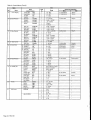
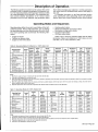
Control Menus
Table 3 lists all
in the Control
possible values
descriptions of
possible menus, items, and adjustable fields
category. The table’s range column lists all
for each adjustable field. Following are brief
the Control category menus.
Control Mode
Menu 11, “Control Mode,” allows you to set the unit for automatic or manual operation. For more information, see the
“Auto/Manual Operation” section in the “Operator’s Guide”
portion of this manual.
Heat/Cool
Menu 12, “Heat/Cool,” contains zone temperature parameters that are used to control the unit’s heating and cooling
equipment. For more information, see the “Description of
Operation” portion of this manual.
Cooling Control
Menu 13, “Clg Control,” contains parameters that are used
to maintain cooling discharge air temperature control. For
more information, see the “Description of Operation” portion
of this manual.
Heating Control
Menu 14, “Htg Control,” contains parameters that are used
to maintain heating discharge air temperature control. For
more information, see the “Description of Operation” portion
of this manual.
Alarm Limits
Menu 15, “Alarm Limits,” contains adjustable
return air temperature
limits that are used
alarms. For more information, see the “Alarm
section in the “Operator’s Guide” portion of this
supply and
to generate
Monitoring”
manual.
Unoccupied
Heating/Cooling
Menu 16, ‘Unocc Htg/Clg,” contains the unoccupied heating
(night setback) and unoccupied cooling (night setup) setpoints that are used to start and run the unit at night when
heating or cooling is required. For more information, see the
“Unoccupied
Control”
section
in the “Description
of
Operation” portion of this manual.
Duct Pressure
Menu 17, “Duct Pressure,” contains parameters that are
used to maintain duct pressure control. These parameters
only have meaning if the unit has been equipped for VAV
applications.
Building Static Pressure Control
Menu 17, “Bldg Pressure,” contains parameters that are
used to maintain direct building static pressure control.
These parameters only have meaning if the unit has been
equipped with the direct building static pressure control
option.
Motor Control
Menu 17, “ Motor Control,” contains parameters that are
used to maintain dual motor control. These parameters only
have meaning if the unit has been equipped with dual motors
for air flow modulation.
Page 10/OM
123
Economizer
Menu 18, “Economizer,” contains parameters that control the
For more information,
see the
optional
economizer.
“Description of Operation” portion of this manual.
Head Pressure Control
Menu 19, “Head Pressure,” contains parameters that control
the optional head pressure control. For more information,
see the “Description of Operation” portion of this manual.
Humidity Control
Menu 19,’’Humidity Ctrl,” contains parameter for humidity
control. For more information,
see the “Description
of
Operation” portion of this manual.
Timers
Menu 20 “Timers,” contains adjustable timer settings that
control the duration of initialization start-up, airflow check,
tenant override, post start-up recirculation
and morning
warm-up operation. The tenant override timer setting is
described in the “Auto/Manual
Operation” section in the
“Operator’s Guide” portion of this manual. The recirculate,
morning warm-up, and low supply temperature alarm delay
timer settings are described in the “Description of Operation”
portion of this manual.
Set Time/Date
Menu 21, “Set Date/Time,” allows you to adjust the current
see the
day, date, and time. For more information,
“Scheduling” section in the “Operator’s Guide” portion of this
manual.
Schedule
Menu 22, ‘iSchedule,” contains the internal scheduling parameters. It also includes an operator override timer that can
be used to start and run the unit for a specified time period.
For more
information,
see the
“Scheduling”
and
“Auto/Manual Operation” sections in the “Operator’s Guide”
portion of this manual.
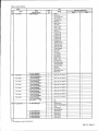
Optimal Start
Menu 23, “Optimal Start” contains the parameters
for
Optimal Start. For more information, see the “Description of
Operation” portion of this manual.
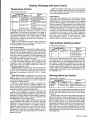
Holiday Date
Menu 24, “Holiday Date,” allows you to schedule 14 holiday
dates. Each date can be assigned a duration from 1 to 5
days. On each day of the holiday period, the holiday schedule entered under menu 22 is used. For more information,
see the “Scheduling” section in the “Operator’s Guide” portion of this manual.
Service
Menu 25, “Service,” contains eight service related items. The
first item, “Mode=,” allows you to place the unit into the
Shutdown service mode. The second item, “Timers=,” allows
you to temporarily speed up most of the controller’s process
timers. For information on these, see the “Auto/Manual
Operation” section in the “Operator’s Guide” portion of this
manual. The third through fifth item, are setup parameters
that specify whether a sensor is connected to the controller.
The seventh item specifies the baud rate. The eighth item,
“IDENT=,” displays the controller’s software part number.
Table 3. Control Menus
Menu
No.
11
I
Item
Name
Control Mode
Name
Field
(Default Shown)
No.
Auto
Switch Key Destination
Range
1
Off-Manual
Menu
Item
1. Unit Status
current unit
Auto
status
Occupied
OCC-COOIOnly
–
Occ-Heat Only
-
Occ-Fan Only
–
Calibrate
12
Heat/Cool
Cntl Temp=
Return
1
@
Return
2. Temperatures
Cntl Temp=
Space
Netwrk
@ OAT
@
13
Clg Control
Mixed
Cooling Spt=
72°F
1
55 – 99°F
2. Temperatures
Cntl Temp=
Heating Spt=
68°F
1
40 – 99°F
2. Temperatures
Cntl Temp=
Clg Dead Band=
f°F
1
O–IO”F
2. Temperatures
Supply Air=
Htg Dead Band=
1‘F
1
O–IO”F
@
Htg PA=
8 Mrh
1
0 – 60 Min
o
Mod Limit=
IO”F
1
1 – 60°F
63
Wait Time=
1 Min
1
1 – 60 Min
@
Max Step=
10%
1
1 – 100%
@
Setpoint=
55 “F
1
40 – IOO”F
@
Dead Band=
1“F
1
O–IO”F
Q
Method=
Nearest
1
55 “F
1
5TF
1
0 – 100”F
Max Spt=
70°F
1
O–IOO”F
Reset=
No Reset
1
Airflow
C38C9Min EWT=
Min Spt=
Nearest I Average
@ 20-
100”F
–
2. Temperatures
Ent Water=–
External
OAT
Return
Space
No Reset
Min Spt @=
14
~ Htg Control
76°F
1
0 – IOO”F
Max Spt @.
71 ‘F
1
O–l
Min Spt @=
76”%
1
0 – 100%
OO°F
Max Spt @=
71°%
1
0 – 100%
Stg Timer=
5 Min
1
5 – 60 Min
@
Mod Limit=
60”F
1
1 – 60”F
@
Wait Time=
30 Sec
1
1 – 60 Sec
@
Max Step=
30 See
1
1 – 60 Sec
@
PA llme=
60 See
1
0 – 255 Sec
63
Setpoint=
100”F
1
40 – 140”F
@
Dead Band=
1“F
1
O–10”F
@
Q
Fan-On Htg=
No
1
Yes I No
Max OAT=
6o°F
1
0 – IOO”F
Min Spt=
60”F
1
40 – 120”F
Max Spt=
120”F
1
40 – 120”F
Reset=
No Reset
1
Airflow
—
2. Temperatures
Supply Air=
2. Temperatures
Outdr Air=
—
External
OAT
Return
Space
No Reset
15
63
Min Spt @=
69°F
1
0 – IOO”F
0
Max Spt C?=
64°F
1
0 – 100°F
Stg Timer=
5 Min
1
2 – 60 Min
@
Mod Limit=
60”F
1
1 – 60”F
63
Wait Time.
30 Sec
1
1 – 60 Sec
@
Max Step=
30 See
1
1 – 60 Sec
63
PA Time.
60 See
1
0 – 255 Sec
Alarm Limits
a
—
Hi Supply=
170”F
1
90 – 250”F
2. Temperatures
Supply Air=
Lo SUPPIY=
40°F
1
20 – 50°F
2. Temperatures
Supply Air=
Hi Return=
120”F
1
90 – 150”F
2. Temperatures
Return Air=
0M123/Pagell
I
Table 3. Control Menus (Cent’d)
Item
Name
@ Duct Pressure
_
3 Bldg Pressure
D Motor Control
) Head Pressure
1 Humidity Ctrl
Tmers
Xme I Date
Field
(Default Shown)
No.
Cooling Spt=
Unocc Htg/Clg
O Economizer
Name
123
Menu
Item
1
55 – 99°F
2. Temperatures
Space=
2, Temperatures
Space=
3, Airflow Mod
Bldg P=
Heating Spt=
55°F
1
40 – 99°F
Clg Diff=
3°F
1
O- IO”F
Htg Diff=
3°F
1
O-lmF
Duct Spt=
1.00”WC
1
0-
Deadbd=
0.08”WC
1
0.000 – 1.Oowc
Max Spt=
2.00”WC
1
.20 -4.00WC
Reset=
No Reset
1
Position
1
No Reset
5.00WC
Mod Lim=
0.040”WC
1
0.020-
Wait Time=
20 Ten
1
10 Ten – 60 Sec
0.250WC
Max Step=
20 Ten
1
10 Ten – 60 Sec
Zone Spt=
o. 050”WC
1
-0.250 – 0,250WC
Min Pos=
60 %
1
0 –loo
%
%
Min Speed=
60 %
1
0 –loo
Deadbd=
0.008”WC
1
0,000 – O.loo”wc
Mod Lim=
0.040”WC
1
0.020 – 0.250WC
Wait Time=
20 Ten
1
10 Ten – 60 Sec
Max Step=
20 Ten
1
10 Ten – 60 Sec
Vel Diff=
41 FPM
1
O-410FPM
3. Airflow Mod
Bldg P=
–
—
5. AirFlow Mod
Current=
Amp Limit=
15 Amps
1
0-99
Min Airflow=
10%
1
0 – 100%
6. Economizer
Position=
@
Enthalpy =
Ves
1
No I Yes
6. Economizer
Econ=
0
Changeover=
75°F
0 – IOO”F
EW’T Diff=
3°F
1
o–IO”F
6. Economizer
—
Econ=
@
-1
Amps
-
@
Dead Band=
I“F
1
O–l O°F
Mod Limit=
6o°F
1
1 – 60”F
Wait Time.
30 Sec
1
1 – 60 Sec
—
Max Step=
30 Sec
1
1 – 60 Sec
—
PA Xme=
60 Sec
1
0 – 255 Sec
—
Setpoint=
160 fXi
1
140–210
Dead Band=
10 psi
1
O–10
psi
10. Mist Status
—
Mod Limit=
30 psi
1
1– 60
psi
Wait Limit=
10 Sec
1
1 – 60 Sec
psi
—
Max Step=
10 Sec
1
1 – 60 Sec
—
None
1
None I Rel Hum I DewPt
–
Enabled=
Occupied
1
Always 10ccupied
–
Sensor=
Return
1
Return / Space
Timer.
10 Min
1
1 –60 Min
Humidity Spt=
50 %
1
o–99%
Humidity Db=
2%
1
o–lo%
DewPt Spt=
50”F
1
O-99°F
DewPt DB=
2°F
1
o–IO”F
Min Stages=
2
1
1–8
Max Stages=
4
1
1–8
Initial=
180 Sec
1
120 – 255 Sec
Recirc=
3 Min
1
1 – 60 Min
Airflow=
2 Min
1
0 Sec – 5 Min
Bypass=
5 Min
1
3–10Min
Ovrde Inc=
2 Hr
1
O–5Hr
1
0-23
2
o–59
3
o–59
1
Sun – Sat
2
1-12
hr:mn:sc
3
1–31
4
o–99
Head Pressure
—
Control=
day mm:dd:yy
Page 12/0M
85°F
Switch Key Destination
Range
10. Mist Status
Humidity
10. Mist Status
Dew Pt
—
—
Table 3. Control Menus (Cent’d)
Menu
Item
Name
(Default Shown)
Name
Schedule
Field
No.
Override=
0.00 Hr
1
0.00 – 5.00 Hr
NMP Sched No.
N/A
1
N/A, 1 – 32
Sun
00:00-00:00
1
:-4
Optimal Start
Holiday Date
Switch Key Destination
Range
I
Menu
—
0–59
Mon
00:00-00:00
(Same as Sunday)
-
Tue
00:00–00:00
(Same as Sunday)
-
Wed
00:00-00:00
(Same as Sunday)
-
Thu
00:00-00:00
(Same as Sunday)
Fri
00:00-00:00
Sat
00:00-00:00
Ho!
00:00-00:00
Opt Start=
off
I
]
-
(Same as Sunday)
I
-
Yes
1
Yes 1 No
Ht Rate=
o.400°F/M
1
0 – 1.000 OFIM
Heat OAT=
35°F
1
-100 –155°F
Ht Factor=
25 Min
1
0 – 255 Min
Cl Rate=
o.400°F/M
1
0 – 1.000 OF/M
Cool OAT=
85°F
1
-100 –155°F
Cl Factor=
25 Min
1
0 – 255 Min
#1 Date=
Dec 25
1
N/A, Jan – Dec
2
0–31
#1 Dur=
1 Day(s)
1
1 – 5 Days
#2 Date=
N/A O
1
N/A, Jan – Dec
2
0-31
#2 Dur=
1 Day(s)
1
1– 5
#3 Date=
N/A O
1
N/A, Jan – Dec
I
1Day(a)
#4 Date=
N/A O
#4 Dur=
1 Day(s)
#5 Date=
N/A O
2
I
1
N/A, Jan – Dec
0–31
I
N/A, Jan – Dec
1 Day(a)
1
1 – 5 Days
1
N/A, Jan – Dec
#6 Dur=
1 Day(s)
1
1 – 5 Days
#7 Date=
N/A O
1,
N/A, Jan – Dec
2
0–31
1
2
I
N/A, Jan-Dee
#8 Dur=
1 Day(s)
1
1– 5
N/A O
1
N/A, Jan – Dec
2
0–31
I
1-
1
1-
1
–
I
–
–
—
I
-
1 – 5 Days
Days
#9 Dur=
1 Day(s)
1
#1 ODate=
N/A O
1
N/A, Jan – Dec
2
0–31
#l ODur=
1 Day(a)
1
1 – 5 Days
#l ODate=
N/A O
1
N/A, Jan – Dec
2
0–31
#l ODur=
1 Day(a)
1
1– 5 Days
#12 Date=
N/A O
1
N/A, Jan – Dec
2
0–31
#12Dur=
1Day(s)
1
1 – 5 Days
#13 Date=
N/A O
1
NIA, Jan – Dec
2
0-31
#13Dur=
1 Day(s)
1
1 – 5 Days
#14 Date=
N/A O
1
N/A, Jan – Dec
2
0-31
1
1 – 5 Days
1 Day(s)
I
0–31
#9 Date=
#14Dur=
—
–
1 – 5 Days
1
I
–
0–31
N/A O
1 Day(s)
—
—
1 – 5 Days
1
#6 Date=
N/A O
—
0–31
#5 Dur=
#6 Date=
–
Days
2
2
#7 Dur=
-
1 – 5 Days
1
II
I
Off I On
Auto Update=
#3 Dur=
-
(Same as Sunday)
(Same as Sunday)
1
Item
-
–
—
–
–
–
–
–
—
Table 3. Control Menus (Cent’d)
Field
No.
Menu
Item
Normal
1
I
Switch Key Destination
Range
Shutdown
limers=
Normal
1
Normal
Fast
Space Sensor=
No
No
1
Yes
Return Sensor=
No
No
1
I
OAT Sensor=
No
1
Alarm Out=
off
1
I
I
No
I
II
Yes
Yes
I
I
off
.
-
Blink
Porf A Baud=
9600
1
IDENT=
950600020
1
12001240019600
–
Notes:
1 Not available for 100 % Outside Air Control Units.
2 Units with Two Motors Only.
3 Units with building static pressure only.
4 Not available for units with no economizer.
5 Not available for units with chilled water.
6 Not available for units with compressors.
7 Not available for units with no heating.
8, Units with head pressure control only.
9 Units with dehumidification control only.
10 Units with zone heating control only.
11. Units with zone control of modulated heating or cooling.
12 Not available for zone control units with compressors and no economizer.
13. Not available for units with staged zone heating control.
14. Units with SAT heating control only.
15. Units with modulated heat only.
16. Units with duct static pressure control only.
17. Units with Airside Economizer Only.
18. Units with Waterside Economizer Only.
19. Not available on all configurations.
20. The minimum EWT varies with unit configuration: 20°F for units with Head Pressure Control and 55°F for units without Head Pressure Control
21. These control temperature methods are not available in all unit configurations.
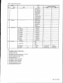
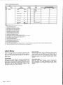
Alarm Menus
4 lists all possible menus and items in the Alarm cateThe table’s range column lists all possible values for
item. Following are brief descriptions of the Alarm catmenus.
Previous Alarm
Menu 27, “Prev Alarm,” tells you what the previous alarm
was and when it occurred. When the current alarm clears, it
moves to this menu. For more information, see the “Alarm
Monitoring” section in the ‘(Operator’s Guide” portion of this
manual.
Current Alarm
Menu 26, “Curr Alarm,” tells you what the current alarm is
and when it occurred. If there is no current alarm, the “No
Active Alarms” message will be displayed. When the current
alarm clears, it moves to the Previous Alarm menu. For more
information,
see the “Alarm Monitoring”
section in the
“Operator’s Guide” portion of this manual.
Compressor
Alarm
Menu 28, “Comp Alarm,” displays an alarm message for
each compressor.” For more information, see the “Alarm
Monitoring” section in the “Operator’s Guide” portion of this
manual.
Table
gory.
each
egory
Page 14/0M
123
Table 4. Alarm Menus
&Aa”,,
,.,
=,.”
Vo.
26
Name
Curr Alarm
I
Item
Name
(Default Shown)
Field
No.
Switch Key Destination
Item
Range
Menu
None
Alarm Mesaage
Filter Dirty
Air Flow Warning
Econo Stuck
No Water Flow
Heat Fail
Mixed T Prob
OAT Prob
Return T Prob
Zone T Prob
Supply T Prob
EWT Prob
Cooling 1 Fail
Cooling 2 Fail
Cooling 3 Fail
Cooling 4 Fail
Cooling 5 Fail
Cooling 6 Fail
AmpSensor
Prob
VelSensor Prob
LoSpd Fan Prob
HiSpd Fan Prob
Freeze Problem
Vanes Stuck
Fan Fail
Low Sllpply T
High Supply T
High Return T
Supply T Fail
Return T Fail
Duct High Limit
Smoke Shutdown
Freeze Shutdown
High Temp Rise
OAT Fail
Zone T Fail
OA Damper Stuck
Mixed T Fail
@ hr:mn mmlddyy
27
Prev Alarm
1. Alsrm Message
(Same as “Curr Alarm”)
-
(Same as “Curr Alarm”)
-
(Same as “Curr Alarm”)
-
(Same as “Curr Alarm”)
-
(Same as “Curr Alarm”)
-
(Same as “Curr Alarm”)
-
(Same as ‘(Curr Alarm”)
-
(Same as “Curr Alarm”)
-
1. @ hr:mn mmlddlyy
Prev Alarm
2, Alarm Message
—
2. @ hr:mn mmlddlyy
Prev Alarm
3. Alarm Message
3. @ hr:mn mmlddlyy
Prev Alarm
4. Alarm Message
.._
4. @ hr:mn mmlddlyy
Prev Alarm
5. Alarm Message
5. @ hr:mn mm/dd/yy
Prev Alarm
6. Alarm Messaga
6. @ hr:mn mm/dd/yy
Prev Alarm
7. Alarm Message
7. @ hr:mn mm/dd/yy
Prev Alarm
8. Alarm Message
8. @ hr:mn mm/dd/yy
No
Clear Buffer=
1
No
Yes
28
CDComp Alarms
High Pressure
#1 =Alarm Message
Water Regulating Valve
–
Frost
Low Pressure
Motor Protection
#2=Alarm
Message
#3=Alarm
Message
#4.Alarm
Message
(Same as #1)
(Same as #1)
—
(Same as #1)
#5=Alarm Meassge
(Same as #1)
#6=Alarm Message
(Same as #1)
Notes:
1. Not available for units with chilled water.
OM 123/Page
15
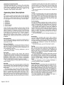
Operator’s Guide
The following “Operator’s Guide” sections provide information on the day-to-day operation of the Self-contained Air
Conditioning Unit Controller. They tell you how to perform
such common tasks as scheduling, displaying and clearing
alarms, and setting the controller for manual operation.
Determining
The MicroTech
Self-contained
Air Conditioning
Unit
Controller provides a variety of information that you can use
to determine the overall status of the unit. At the keypad/display, most of this information can be found under menus 1
through 10. The following are available:
●
●
●
●
●
●
●
●
●
●
Unit status
Cooling status
Heating status
Temperatures
Pressures
Fan/Airflow status
Airflow Mod (differential
Economizer positions
Operating Hrs position
Mist Status
pressure switch)
The unit status state (menu 1) tells you the overall state that
the unit is currently in. At the keypad, it can be displayed
simply by pressing the “Status” key. Except for the Calibrate,
every unit status state displayed is an operating state.
Operating States
Operating states define the overall status of the unit under
the various conditions that may occur during normal operation. The following operating states are possible:
●
9
●
●
●
●
●
●
9
●
●
off
Start-up Initialization
Recirculate
Post Heat
Fan On
Fan On-Heating
Economizer
Cooling
Morning Warm-up
Heating
Unoccupied Economizer
Unoccupied Cooling
Unoccupied Heating
For detailed
information
on these states,
“Operating
States
and Sequences”
section
“Description of Operation” portion of this manual.
123
Off-Unoccupied
When the unit is shut down by a scheduling function, all cooling will be disabled, and the cooling status will be OffUnoccupied.
Off-No Flow
When no water is flowing to a unit and no airside economizer is enabled, all cooling will be disabled and the cooling status will be Off-No Flow.
Off Temperature
When Economizer is not present or Economizer is disabled
and the EWT is too low for compressor operation, the cooling status is Off Temperature. Waterside economizer and
compressor operation are disabled during Off-Temperature.
Network Disable
If the cooling status is Network Disable, it means that a network command has disabled all cooling.
Switch Disable
If the cooling status is Switch Disable, it means that the
switches on a field supplied device have been set to disable
cooling. All cooling will be disabled during the Switch Disable
state.
Manual Disable
If the cooling status is Manual Disable, it usually means that
the control mode (menu 11) has been set to one of the following: Off-Manual,
Occ-Heat Only, Occ-Fan Only, or
Calibrate. The Manual Disable cooling state can also occur
if the controller is in the Shutdown service mode (menu 25).
All cooling will be disabled during the Manual Disable state.
see
in
the
the
Calibrate
The Calibrate state is a special state that will only occur
when the control mode (menu 11) is set to “Calibrate.”
During the Calibrate state, the controller automatically cali-
Page 16/0M
brates the position feedback pots on the economizer damper
and supply fan inlet vane actuators. It also calibrates all the
unit’s static pressure transducers.
For more information on Calibrate, see the following
“Auto/Manual Operation” section.
The cooling status (menu 7) tells you whether cooling is
enabled or disabled. If cooling is disabled, the reason is
given. Following are descriptions of the various cooling status states.
Unit Status
●
Unit Status
Cooling Status
The first three items are very useful because they summarize the unit’s status. Using them, you can quickly determine
whether the unit is, for example, off, starting-up, heating, or
cooling. If heating or cooling is disabled for any reason, you
can find out why. Following are descriptions of the possible
“unit status,”” cooling status,” and “heating status” states.
●
For detailed information on the control processes and
their programmable
setpoints and parameters,
see the
“Description of Operation” and “MicroTech Control Features”
portions of this manual.
Off-Alarm
When the unit is shut down by an alarm, all cooling will be
disabled, and the cooling status will be Off-Alarm.
Compressors
Only
When the entering water temperature (outside air) is too
warm for free cooling, but not cool enough to prevent
mechanical cooling operation, the cooling status will be
Compressors Only. In this state the unit will use mechanical
cooling as required to maintain the cooling setpoints.
Economizer operation will be disabled, and the water valve
(outside air damper) will be held at its minimum position.
This status also appears when the unit does not an economizer.
Economizer Only
When the entering water temperature (outside air) is cool
enough for free cooling and mechanical cooling is disabled,
the cooling status will be Economizer Only. In this state the
unit will use the economizer as required to maintain the cooling setpoints. Mechanical cooling will be disabled.
All Cooling Allowed
When the entering water temperature (outside air) is cool
enough for free cooling, but not cool enough to prevent
mechanical cooling (compressorized
or chilled water), the
cooling status will be All Cooling Allowed. In this state the
unit will use the economizer
or mechanical cooling as
required to maintain the cooling setpoints.
Manual Disable
If the heating status is Manual Disable, it usually means that
the control mode (menu 11) has been set to one of the following: Off-Manual,
OCC-COOI Only, Occ-Fan Only, or
Calibrate. The Manual Disable heating state can also occur
if the controller is in the Shutdown service mode (menu 25).
All heating will be disabled during the Manual Disable state.
Off-Alarm
When the unit or its heating equipment is shut down by an
alarm, all heating will be disabled, and the heating status will
be Off-Alarm.
Heating Allowed
When the outside air is not warm enough to prevent heating
operation, the heating status will be Heating Allowed. In this
state the unit will supply heat as required to maintain the
heating setpoints.
Mist Status
Heating Status
The heating status (menu 8) tells you whether heating is
enabled or disabled. if heating is disabled, the reason is
given. Following are descriptions of the various heating status states.
Off-OAT Lockout
When the outside air is too warm for heating operation, the
heating status will be Off-OAT Lockout. In this state the unit’s
heating equipment will be disabled.
Off-Unoccupied
When the unit is shut down by a scheduling function, all
heating will be disabled, and the heating status will be OffUnoccupied.
Network Disable
If the heating status is Network Disable, it means that a network command has disabled all heating.
Switch Disable
If the heating status is Switch Disable, it means that the Heat
Enable input is open. All heating will be disabled during the
Switch Disable state. This status also appears when heat is
not installed.
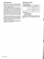
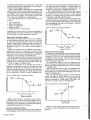
Auto/Manual
Electric shock and moving machinery
Heat Output
The Heat Output is in the Cool(closed) position during normal operation. It is in the Heat(open) position when: 1) heat
is supplied; 2) during the Recirculation period; 3)during the
Post Heat period; 4)during the Start Initial state to keep the
pump off; 5)during the unoccupied period when the Fan On
output is on to keep the pump off during the unoccupied period. The Heat Output may not be used for signaling external
heaters. The Heat Output is displayed on keypad menu #10.
Outdr Dmpr
The status indicates the position of the outdoor air damper
(open or closed).
Head Pressure
A water regulating valve (WRV) modulates the flow to the
condenser in response to a refrigerant pressure signal. The
refrigerant pressure is displayed on keypad menu #10.
Humidity and Dewpoint
An analog sensor is mounted in either the space or return
duct to sense relative humidity. The percent relative humidity and a calculated dewpoint are both displayed on keypad
menu #10.
Operation
hazard. Can cause severe personal injury or death.
When the unit is in the Off operating state, power is not removed from the unit controller or components.
off by means of the unit disconnect switch before servicing line voltage equipment or entering the unit.
Lock power
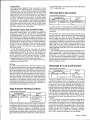
Control Mode
Programmable
Parameters
Keypad/Oisplay
Menu
11. Control Mode
ID
I
Item
Auto
Parameter Name
Control Mode
You can set up the unit for automatic or manual operation by
selecting the unit’s control mode with the Control Mode paraFollowing are descriptions of the seven possible conmeter.
trol modes.
0M123/Page17
Off-Manual
The Off-Manual control mode will place the unit into the OffManual operating state (see warning above). In the Off state
the unit is shut down. For more information on operating
states, see the ‘rOperating States and Sequences” section of
this manual.
Caution: The Off-Manual control mode can be overridden by an operator at a remote PC or RMC Panel (if any). To
eliminate this risk, disconnect unit power or disconnect the
communications
cable from MCB1. This risk can also be
eliminated by placing the unit into the Shutdown service
mode (see below).
Auto
The Auto control mode allows the unit to operate automatically. This means that the unit will start and stop according
to any external on/off switch, scheduling, tenant override,
operator override, or unoccupied temperature control commands. Once running, the unit will act as required to maintain its temperature and pressure control setpoints.
Occupied
The Occupied control mode causes the unit to run continuously in the occupied mode. Any scheduling commands are
prevented from shutting down the unit. Both heating and
cooling are allowed to operate as necessary to maintain the
temperature control setpoints.
Service Mode
Programmable
Menu
Occ-Heat Only
The Occ-Heat Only control mode causes the unit to run continuously in the occupied mode. Any scheduling commands
are prevented from shutting down the unit. Heating is
allowed to operate as necessary to maintain the temperature
control setpoints. Cooling is disabled.
Occ-Fan Only
The Occ-Fan Only control mode causes the unit to run continuously in the occupied mode. Any scheduling commands
are prevented from shutting down the unit. Both heating and
cooling are disabled.
Calibrate
The Calibrate control mode automatically calibrates the position feedback pot on the economizer valve (outdoor air
damper) and VIV actuators. It also calibrates all the unit’s
static pressure transducers. Following is a description of the
Calibrate procedure.
After Calibrate is selected, the controller shuts down the
fans and drives open the economizer valve (outdoor air
dampers or vanes) when three minutes have elapsed, the
controller records the feedback value of the actuator as
equivalent to its fully open position. The controller then drives the actuator closed. When three minutes have elapsed,
the controller records the feedback value of the actuator as
equivalent to its fully closed position. Since there is no airflow through the unit, the controller records the input voltages of all connected pressure transducers as equivalent to
0.000w.c.
After the Calibrate procedure is complete, the controller
shuts down the unit and places it into the Off-Manual control
mode. The unit can be restarted by changing the control
mode.
Note: Inverters are not calibrated.
Page 18/OM
123
ID
Item
I
25. Seivice
Mode= Normal
Parameter
Name
Service Mode
There are two service modes that can be selected only at the
keypad with the Service Mode parameter: Shutdown and
Normal. When the Shutdown service mode is selected, the
unit is placed into the Off-Service operating state. In the Off
state the unit is shut down. For more information on operating states, see the “Operating States and Sequences” section of this manual.
Unlike the Off-Manual control mode, the Shutdown service mode cannot be overridden by an operator at a remote
PC or remote keypad. The only way to return the unit to normal operation is to select the Normal service mode at the
keypad on the unit. This feature is meant to be used by a
service technician who needs both power in the unit and
assurance that the unit will not start unexpectedly.
Tenant Override
Programmable
Parameters
Keypad/Display
Manu
OCC-COOI Only
The OCC-COOIOnly control mode causes the unit to run continuously in the occupied mode. Any scheduling commands
are prevented from shutting down the unit. Cooling is
allowed to operate as necessary to maintain the temperature
control setpoints. Heating is disabled.
Parameters
Keypad/Display
20, Timers
I
ID
Item
Ovrde Inc= 2,00 Hr
Paramatar
Name
Override Increment
There are two types of tenant override functions: timed and
nontimed. Both types place the unit into occupied operation
regardless of any scheduling features. The control mode
(menu 11) must be set to ‘iAuto” to use the tenant override
features.
Additional information is provided in the “Field Wiring”
portion of Bulletin No. IM 608, MicroTech Self-contained Air
Conditioning Unit Controller.
Timed Tenant Override
The tenant override switch provided with several of the zone
temperature sensor packages can be used to override unoccupied operation for a preprogrammed time period. You can
set this time period with the Override Increment parameter,
which can be set for any amount of time up to 5 hours in 15minute increments (default is 2 hours at Menu 20).
When an occupant presses the push button switch on the
zone sensor (S PTI), the Override Timer (menu 22) is set
equal to the Override Increment. The unit will then start and
run until the Override Timer expires. If the tenant override
switch is pressed again while the unit is operational, the
Override Timer will reset and the unit will continue to operate
for another Override Increment. For example, assume that
the Override Increment is two hours. One press of the override button will provide at least two hours of unit operation. If
the button is pressed again one hour later, the Override
Timer will be reset to two hours, and thus a total of three
uninterrupted hours of operation will result provided the main
switch (S2) is in the ‘(Auto” mode and everything else is in
the Auto mode also.
Nontimed Tenant Override
A simple SPST switch connected to the “External on/off terminals on the output board can be used to override unoccupied operation. When this switch is closed, the unit will start
and run in the occupied mode provided the main switch (S2)
is in the ‘(Auto” mode. When this switch is open, the unit will
be controlled by any active scheduling function (internal, network, or external time clock). If there is no active scheduling
function, the unit will remain in the unoccupied mode.
Operator Override
Fast Timers
Programmable
Programmable
Parameters
Keypad/Display
Menu
22. Schedule
ID
Item
I
Override= 0.00 Hr
KeypadiOiaplay
Parameter Name
Override Timer
Parameters
Menu
Item
Timers= Normal
25, Service
From the keypad or PC, you can manually set the same
Override Timer that is automatically set by the tenant override switch and Override Increment parameter (see “Tenant
Override” above). When the Override Timer is set to a nonzero value, the unit will start and run in the occupied mode
regardless of any scheduling features provided the main
switch (S2) is in the “Auto” mode.
The unit will stop when the timer expires. Like the Override
Increment parameter, the Override Timer can be set for any
amount of time up to 5 hours in 15-minute increments. The
control mode (menu 11) must be set to “Auto” to use the
operator override feature.
Note: If the Override Timer’s remaining time is larger than
the Override Increment, pressing the tenant override button
on the space sensor will have no effect. If the Override
Timer’s remaining time is less than the Override Increment,
pressing the tenant override button will reset the Override
Timer to the Override Increment.
ID
I
Parameter
Name
Operation Tming Flag
If desired, you can temporarily speed up most of the controller’s internal timers by using the Operation Timing Flag.
When set to “Fast,” the Operation Timing Flag will temporarily reset the settings for the following timers to 20 seconds:
●
Start-up initialization timer
. Recirculate timer
●
Low supply temperature alarm. delay timer
●
Cooling interstage timer
●
Heating interstage timer
The timer settings will return to normal if (1) the Operation
Timing Flag is set to “Normal” or (2) no keypad action occurs
for 15 minutes. The purposes of these timers are described
in the “Description of Operation” portion of this manual.
Caution: This fast timers feature is meant to be used only
by a knowledgeable service technician to facilitate testing
the unit. Prolonged operation in this mode could damage the
unit.
Scheduling
The self-contained unit with the control mode set to auto can
be scheduled for daily and holiday operation by using any
one of the following four methods:
1. Unit controller internal scheduling
2. Network Master Panel (NMP) scheduling
3. Remote Monitoring and Control (RMC) Panel scheduling
4. External time clock
The following sections describe how to use the unit controller’s internal scheduling features. Internal parameters
that must be set to use any of the other three scheduling
methods are also discussed.
For information on how to use the NMP and RMC Panel
scheduling functions, refer to the literature provided with
these panels.
Setting Time and Date
Programmable
Parameters
Keypad/Display
Menu
24. Set Time/Date
ID
Item
Parameter Name
hrmn:sc
Current Time
day mm:dd:yy
Current Date
The MicroTech controller uses the date and time to execute
its internal scheduling functions. Once set, the battery
backed internal time clock will keep the current time regardless of whether power is being supplied to the unit.
You can set the time of day by entering the hour (O-23),
minute (O-59), and second (O-59) into the Current Date
parameter’s three fields. You can set the date by entering the
day (Sun-Sat), month (1-1 2), date (1-31 ), and year (O-99)
into the Current Date parameter’s four fields.
Daily Scheduling
Programmable
Parameters
Keypad/Display
Menu
Sun
22. Schedule
ID
Item
I
00:00-00:00
~0040:00
I
Parameter
Name
Sunday Schedule
I Monday Schedule
Tue
00:00-00:00
I Tu esday Schedule
I wed
0000-00:00
I Wednesdav
I
NMP Sched No. N/A
Schedule
I Network Master Panel
When the unit is in the Auto control mode (menu 11), the unit
will start and stop according to the controller’s internal
schedule. YOUcan set one start and one stop time for each
day of the week and for designated holidays (see below). An
example of how to use the keypad to enter or modify a
schedule is given in the “Getting Started” portion of this manual.
As shown in Figure 5, each daily schedule has four
adjustable fields: start hour, start minute, stop hour, and stop
minute. The schedule shown in Figure 5 would cause the
unit to start up at 6:30 a.m. and shut down at 6:00 p.m. every
Monday.
Figure 5. Daily Schedule Fields
m=~E
Mon 06:30–18:00
OM123/Page19
I
For continuous unit operation, set the schedule fields to
“00:00-23:59.” To keep the unit off for the entire day, set the
schedule fields to “00:00-00:00”
(this is the default setting).
Note: An internal daily schedule’s start time must occur
before its stop time; otherwise, the unit will not start that day.
If you want to schedule the unit to shut down and then start
up again on the same day, you must use an NMP schedule
or an external time clock.
NMP Scheduling
If the unit controller is included in a MicroTech network with
a Network Master Panel, an NMP schedule can be used
instead of the internal schedule. To use an NMP schedule,
the unit controller’s Network Master Panel Schedule parameter must be set to the desired NMP schedule number.
When the control mode (menu 11) is set to “Auto,” the NMP
schedule you selected will start and stop the unit.
Using an External Time Clock
If desired, an external time clock can be used to schedule
unit operation. In this case, all internal daily schedules must
be set to “00:00-00:00
(this is the default setting). When the
control mode (menu 11) is set to “Auto,” the external time
clock will start and stop the unit.
Holiday Scheduling
Programmable
Parameters
Keypad/Display
Menu
22. Schedule
ID
Item
Hol
00:00-00:00
NMP Sched No. N/A
Parameter
Name
Holiday Schedule
Network Master Panel
Schedule
24. Holiday Date
#’ Oate= Dec 25
Holiday Date #’
#’ Dur= 1 Day(s)
Holiday Date #’
You can schedule special operating hours for up to 14 holiday periods by using the controller’s holiday scheduling feature. (The wildcard character in the above table could be any
number between 1 and 14.) Whenever a holiday date
occurs, the controller will use the Holiday Schedule’s start
and stop times for the number of successive days specified
by the associated holiday date duration parameter. For
example, assume that this year Christmas Eve occurs on a
Thursday. Your building will be shut down on both Christmas
Eve and Christmas Day, but will operate normally on the
weekend. To schedule this holiday, set the Holiday Schedule
to “00:00-00:00”; set the Holiday Date #1 parameter to “Dee
24; and set the Holiday Date #1 Duration parameter to “2
Days.”
If any of the 14 holiday dates are not required, enter “N/A
and “O into the fields of those holiday dates (except for
Holiday Date #1, this is the default setting).
To use the internal holiday scheduling
feature, the
Network Master Panel Schedule parameter must be set to
“N/A (this is the default setting).
Alarm Monitoring
About Alarms
The Self-contained Air Conditioning Unit controller is programmed to monitor the unit for specific alarm conditions
that may occur. If the unit controller detects an alarm condition, it will indicate the alarm, identify the alarm, and execute
appropriate control actions that will fail-safe the unit. For
detailed information on these alarm-specific control actions,
see the ‘(Alarm Control” section in the “Description
of
Operation” portion of this manual.
Programmable
Parameters
Keypad/Display
Menu
25. Service
ID
Item
Parameter
Name
Alarm Out= Blink
Alarm indication
Alarm Out= Oft
Alarm indication
Alarm Indication
Under normal (non-alarm) conditions, the amber status LED
on MCB1 will be continually lit and the. alarm output will be
energized. The alarm output’s LED indicates the state of the
output: On indicates energized and off indicates deenergized. Both N/O and N/C contacts are available. Typically,
the alarm output would be connected to some type of fieldsupplied annunciator.
The method of alarm indication is set at Blink or Off at
menu 25. Setting the Alarm Out= Blink cause the amber status LED on MCBI to blink during alarm conditions. Setting
the Alarm Out= Off causes the amber status LED to be off
during alarm conditions. The Alarm Out=Off setting is used
when communicating an alarm condition to a building management control system.
Note that the dirty filter alarms have a unique alarm indication. Instead of flashing on and off in equal one-half secPage 20/ OM 123
ond intervals, the amber status LED and the alarm output
LED will flash on for 9/1 O second and off for 1/10 second
when a dirty filter alarm occurs. The controller’s dirty filter
alarms are caused by a pressure drop (sensed by PS5)
exceeding a field adjustable limit. The limit is set at 0.60 WC
pressure drop at the factory. Adjustment at the sensor allow
the limit to range from 0.17 to 5.00 WC pressure drop.
Priority
The various alarms that can occur are prioritized according
to their severity. Three categories are possible: faults, problems, and warnings. Regardless of the alarm type, a message that identifies the alarm will be generated for display at
the keypad/display or PC. Table 5 summarizes the alarms
that can occur in CAV-ZTC units in the order of priority.
Faults: Faults are the highest priority alarms. If a fault
occurs, the unit will be shut down until the alarm condition is
gone and the fault is cleared. Most fault alarms must be
manually cleared.
Problems: Problems have lower priority than faults. If a
problem occurs, the unit will not be shut down, but its operation will be modified in some way to compensate for the
alarm condition. Most problem alarms will automatically
clear when the alarm conditions that cause them return to
normal.
Warnings: Warnings are the lowest priority alarms. No
control action is taken when a warning occurs; it is simply
indicated to alert the operator that the alarm condition needs
attention. Most warning alarms will automatically clear when
the alarm conditions that cause them return to normal.
Alarm priority also exists within each category. The
alarms in Table 5 are listed according to their priority. For
example, in the fault category, the Freeze Shutdown alarm
has higher priority than the Fan Failure alarm.
Table 5. CA V-ZTC Unit Alarms
Alarm
Type
Fault
.= =-= . .. .. . .. . .
,----
Smoke Shutdown
O
I
I
.
Duct High Limit
Duct High Limit ,,, “,-, ,,, ~“.,.t.-,,
Zone Sensor Fail
Zone
temperature
MAT Sensor Fail
,,,., ;~ o~+har~hfi~o~ n, finon
Mixed Air Temperature se”=fi”
OAT temperature
!“,
“u!,
--,
I
L.!,
High Return Temp
”,
I
1
I
I
IV, a!
I
Manual
. . . .H...
.
lVld
Udl
sensor failed while it was the Control Temperature source
OAT Sensor Fail
Fail
,Do* Qon.nr
Sup Sensor Fail
Problem
.. .
Smoke detecte
,0
V!
L!!U!
.,,
,”,,-”
“!
“pull,
sensor is
I either shorted or open.
Rd,
sensor failed while it was the Control Temperature source
,.
-..,.,- ]rn air temperature
..
Supply air tempm=.rat,
----- tro
concnr
faild
----------
Return air temperature
exceeded the High Return Temperature
Manual
Manual
1
High Supply Temp
Supply air temperature
exceeded the High Supply Temperature
Low Supply Temp
Supply air temperature
fell below the Low Supply Temperature
Limit setting (menu 15)
Limit setting (menu 15)
Limit setting (menu 15)
,LJa,
kAo”#,31
IVlullum!
Manual
Manual
Manual
Fan Fail
Aidlow not proven after the airflow check timer expired (default setting is 2 minutes)
OA Damper Stuck
Outside air damper is stuck.
Manual
Supply Vane Stuck
Variable Inlet Vanes are more than 25% open after units been off for three minutes.
Manual
. . .. .
“’-”‘u
VVGLG
Freeze Problem
Freeze condition occurredd ‘“’h”VVIIIIG ‘--”
Ialla
Hi Spd Fan Prob
No air flow is sensed after two minu ltes of operation
Manual
Manual
/+u[u
“t,
Lo Spd Fan Prob
!G,,.,L.MU,,u,
No air flow is spm~a~
~++ori,~,mm;nl
I
,.rv ,,llll.les
Vel Sensor Prob
Air velocity is kess than 215 FPM.
Manual
Amp Sensor Prob
Amp sensor equals zero after airflow has been proven
Manual
High refrigerant pressure, low refrigerant pressure, frost switch in alarm position or a
Auto
Cooling #6 Fail
compressor
Cooling #5 Fail
Cooling #4 Fail
of operation
motor protector trip condition occurred in refrigeration circuit #6
High refrigerant pressure, low refrigerant pressure, frost switch in alarm position or a
compressor
High refrigerant pressure, low refrigerant pressure, frost switch in alarm position or a
Cooling #2 Fail
Auto
circuit #4
High refrigerant pressure, low refrigerant pressure, frost switch in alarm position or a
compressor
Auto
motor protector trip condition occurred in refrigeration circuit #5
compressor motor protector trip condition occurred in refrigeration
Cooling #3 Fail
1
Manual
Auto
motor protector trip condition occurred in refrigeration circuit #3
High refrigerant pressure, low refrigerant pressure, frost switch in alarm position or a
Auto
compressor motor protector trip condition occurred in refrigeration circuit #2
Cooling #1 Fail
High refrigerant pressure, low refrigerant pressure, frost switch in alarm position or a
compressor
EWT Sensor Prob
@ Zone Sensor Prob
Warnina
Auto
motor protector trip condition occurred in refrigeration circuit #1
Entering water temperature
Zone temperature
Auto
sensor failed
sensor failed when it was not control temp or no return sensor present
Ret Sensor Prob
Return air temperature
OAT Sensor Prob
Outside air temperature
Mix Sensor Prob
Mixed air temperature
sensor failed while it was not the Control Temperature
source
Auto
Auto
sensor failed
Auto
sensor failed
by 60°F
Manual
High Temp Rise
Supply air temperature
Heat Fail
Safety lockout condition occurred in electric heat
Auto
No Water Flow
Lack of water flow is indicated by an open water flow switch
Auto
Economizer
Economizer not fully closed during unit shutdown or not fully open during mechanical
Stuck
exceeds Mixed air temperature
Auto
cooling operation with conditions acceptable for economizer operation
Manual
Air Flow Warning
Airflow indicated while fans were off
Auto
Filter Dirty
Pressure drop input across filter is in the alarm position
Auto
Notes:
1. A manual reset is required at smoke detector SDI before the Smoke Shutdown alarm can be cleared.
2, The Zone Sensor Problem alarm will occur if the Zone Temperature sensor fails while it is not the Control Temperature source or if there is a Return Temperature
sensor.
3. The Zone Sensor Fail alarm will occur only if it is the selected Control Temperature source and there is no Return Air Temperature sensor
Displaying Alarms
Programmable
Parameters
Keypacf/Display
ID
Menu
Item
26. Curr Alarm
Alarm Message
27..,Prev Alarm
Clear Buffer= No
Parameter
Name
Clear Buffer Flag
Current Alarm
When the controller indicates that an alarm condition has
occurred, you can find out what it is and when it happened
by displaying the current alarm (menu 26) at the keypad or
PC. (To do this at the keypad, simply press the alarms key.)
The current alarm will remain current until either it clears
(see below) or a higher priority alarm occurs.
Previous Alarm Buffer
When the current alarm is cleared or replaced by a higher
priority alarm, it is stored in the previous alarm buffer (menu
27). The previous alarm also includes the time and date of
occurrence. The previous alarm buffer holds the last 8
alarms in chronological order. The first item in the alarm
buffer is more recent than the next item and so on. When a
new alarm is added to the alarm buffer, the last item in the
buffer is dropped.
If desired, you can clear the alarm buffer by changing the
Clear Buffer Flag to “Yes.” It will automatically change back
to “No” after the buffer is cleared.
OM 123/ Page 21
Clearing Alarms
Before any alarm can be cleared, the alarm conditions that
caused it must have returned to normal. When the alarm
conditions are gone, an alarm may be cleared either automatically or manually. See Table 5. (“Clearing” an alarm is
the same as “resetting” an alarm.)
Alarms are arranged in increasing priority. A higher priority alarm replaces a lower priority alarm. An auto-reset alarm
will immediately clear whenever the alarm conditions that
caused it disappear. You can clear a manual-reset alarm at
the keypad/display or PC. To clear an alarm from the keypad, simply press the clear key while the current alarm
(menu 26) is in the display. Any alarm may also be cleared
by placing the S2 switch on the front of the unit to Off and
back to Auto or On. The eight previous alarms and the dates
and times when they occurred are found in keypad Menu
#27.
Compressors that are disabled due to alarm conditions
are displayed on Menu #28. These alarms do not appear on
menu #26 if a higher priority alarm occurred that cleared the
compressor alarm and the compressor alarm conditions no
longer exist. In this situation, the compressor alarms may
only be cleared through Menu #28.
Note: Some of the safety devices that detect alarm conditions require a manual reset at the device before the controller alarm can clear. See Table 5.
Setting Alarm Limits
Programmable
Parameters
Keypad/Oisplay
Menu
15, Alarm Limits
I
ID
Parameter
Item
Name
1
Hi Supply= 170mF
High Supply Temperature
Limit
LO %rlp$’=
40”F
Low Supply Temperature
Limit
Hi Return= 120”F
High Return Temperature
Three alarms in Table 5 have adjustable limits that are used
to trigger the alarm:
●
High Supply Temperature
●
Low Supply Temperature
●
High Return Temperature
Although the default settings should be suitable for most
applications, you can set these alarm limits as necessary
with the keypad or a PC. The default settings are shown
above.
I
Page 22/ OM 123
I
Description
of Operation
them. Before changing any setpoints or control parameters,
you should read and understand the sections that apply to
your unit.
For detailed information on the Step-and-Wait function,
which controls the unit’s modulating valves and dampers,
see the “MicroTech Control Features” portion of this manual.
The following sections describe how the various VAV control
processes work to maintain temperature and pressure control. The “Operating States and Sequences” section provides
an overall description of unit operation. The subsequent sections provide detailed descriptions of the various control
processes and how their setpoints and parameters affect
Operating States and Sequences
Operating states define the current overall status of the Selfcontained system. With a single keystroke, you can display
the operating state and thus quickly assess the unit’s condition. Each operating state summarizes the following information:
●
●
●
●
●
●
●
●
Heating system status
Airside and waterside economizer status
Mechanical cooling system status
Occupied output status
VAV/Heat output status
Tables 6 and 7 show the operating states and the status
information. Table 6 is for Mixed Air or 100% Return Air Unit
and Table 7 is for 100% Outside Air Units.
Supply fan status
Outdoor air damper status
Supply fan inlet vane status
Table 6. Operating States for Mixed Air or 100% Return Air
vparaung
sra~e
Fans
(Unit Statua)
I
oft
..
off
.
I
Airflow
I
Airflow
I
OO/.Flow
I
Waterflow
I
Heat
Enabled
output
output (K6)
(K15)
No
No
Closed
off
No
No
Open
Closed
off
No
No
Open
Closed
Closed
off
Yes
No
Open
Closed
Yes
No
No
No
,
off
off
Minim!]m
I
:ooling
cnameo
off
Minimum
, _r...
I
Closed
Minimum
-..
On
Fan On
I output
I Closed
I
Modulating” I (3 Min[mum or Ooen
off
I
[ @ Off or ODen I
Yes
I
No
NO
I
Yes
ODen
@ O~en
Ciosed
O~en
Closed
Ciosed
I
I
Closed
I
Closed
Closed
Closed
I
Closed
I
Notes:
1. The Fan On output will open 3 minutes after the unit enters the Off state.
2. This state is not applicable to cooling only units.
3. When the outdoor air enthalpy is low, the economizer’s outside air dampers will be fully open; when the outdoor air enthalpy is high, the economizer’s outside
air dampers will be at minimum position.
4. When the outdoor air enthalpy is low, the airside economizer’s outside dampers will be fully open; when the outdoor air enthalpy is high, the airside economizer’s outside dampers will be fully closed.
5. Waterside Economizer will be Off if the temperature delta between EWT and MAT is less than the differential.
Table 7. Operating
I
States fo 100% OutdoorAir
Operating State
supply
(Unit Statua)
Fan
Outside
supply
Waterside
Air
Fan
Economizer
Damper
Airflow
Waterflow
@ Closed
—
O% Flow
off
Mechanical
VAVI
Occupied
Cooling
Heat
output
Enabled
output (K6)
No
No
Open
Heat
Enabled
(Kl 5)
@ Open
Open
Minimum
off
No
No
Open
Closed
Open
Modulating
off
No
No
Closed
Closed
Open
Modulating
off
Yes
No
Closed
Closed
@ Economizer
On
Open
Modulating
Modulating
No
No
Closed
Closed
Cooling
On
Open
Modulating
Off or Open
No
Yes
Closed
Closed
0 Heating
On
off
Yes
No
ODen
@ Fan On
..- ....=
F=l=
0
Closed
@ Unoccupied
Econ
On
Modulating
Closed
Unoccupied
~ I Innrmmid
Cooling
On
Off or Open
Closed
Hoatinn
fln
off
Closed
Notes:
1. The outside air damper will close 3 minutes after the unit enters the Off state.
2. The Fan On output will open 3 minutes after the unit enters the Off state.
3. Waterside Economizer will be Off if the temperature delta between EWT and MAT is less than the setpoint at menu 18 (EWT Diff=).
4. This state is possible only on units that have a waterside economizer.
5. This state is not applicable to cooling only units.
OM 123/ Page 23
1
Displaying the Operating State
The current unit status (menu 1) shown is the current operating state. At the keypad, you can display the current unit
status simply by pressing the Status key. For more information, see the “Determining
Unit Status” section in the
“Operator’s Guide” portion of this manual.
overridden and the supply fan inlet vanes are forced to a
minimum position (17% open, fixed). The economizer maintains its previous position (closed or minimum), cooling and
heating are disabled, and the VAV/Heat output remains
open.
For more information on Post Heat, see the “Supply Fan
Airflow” section.
Operating State Descriptions
Fan On
The Fan On operating state occurs during occupied operation when cooling and heating are either not required or disabled. During Fan On, the economizer dampers are at minimum position, and cooling and heating are disabled. The
VAV/Heat output is closed (auto) and normal duct static
pressure control is maintained.
off
Any of these conditions
All of them must be in
Off-service is a safety
the unit keypad. It can
1.
2.
3.
4.
5.
6.
will prevent the unit from operating.
the Auto position to allow operation.
feature that can only be changed at
not be set though a remote keypad.
Off-Alarm
Off-Service
Off-Manual
Off-Network
Off-Unoccupied
Off-Fan Switch
These Off states are prioritized as shown above; the OffAlarm state has the highest rank. Assigning priority to the Off
states is essential. For example, if a unit is in the Off-Service
state, an operator at a remote network PC would not be able
to start that unit by removing the Off-Network command.
(The Off-Service state occurs when a unit controller is
placed into the Shutdown service mode.) If a unit is in the
Off-Alarm state, nothing could start that unit until the alarm
is cleared.
Start Requested
The Start Requested state is a transitional operating state. It
will be momentarily displayed whenever the unit has been
commanded to start.
Start-up Initialization
The Start-up Initialization operating state always occurs
after the Off and Start Requested states when the unit
been commanded to start. During Start-up Initialization,
unit is prepared for start-up.
For more information on Start-up Initialization, see
‘(Start-up Control” section.
just
has
the
Fan On-Heating
The Fan On-Heating operating state is similar to Fan On.
The difference is that heating is enabled to prevent the discharge air temperature from falling below the current discharge air cooling setpoint during the Fan On-Heating state.
By supplying heat instead of closing the outside air
dampers, the Fan On-Heating state assures that proper discharge air temperatures are maintained without sacrificing
indoor air quality. This feature is particularly valuable for
buildings in colder climates that have high minimum outdoor
air volume requirements.
For more information, see the “Heating: Modulating” section.
Economizer
The Economizer operating state occurs when cooling is
required to satisfy the occupied cooling setpoints and free
cooling is available. During the Economizer state, mechanical cooling and heating are disabled. The economizer valve
or dampers are modulated to maintain the discharge air
cooling setpoint.
For more information, see the “Economizer” section.
Recirculate
The Recirculate
operating
state begins after Start-up
Initialization when the fan is energized. It allows temperature
conditions throughout the unit and space to equalize before
temperature
control begins. This feature is particularly
important for applications in which the return air temperature
sensor is being used for heatlcool changeover control.
For more information on Recirculate, see the “Start-up
Control” section.
Cooling
When mechanical cooling is required during occupied operation, the unit enters the Cooling state. Depending on the
outside air enthalpy, the economizer valve or dampers will
either be fully open or at minimum position during Cooling.
Cooling will be supplied as required to maintain the discharge air cooling setpoint.
On units equipped with modulating chilled water, the unit
status display will show “Cooling” during the Cooling state.
On units equipped with compressors, the unit status display
*“ during the Cooling state. The
will show “Cooling-Stage
wildcard character indicates the number of active cooling
stages.
For more information, see the “Cooling: Multistage” or
“Cooling: Modulating” section, as applicable.
Post Heat
Post Heat eliminates duct overpressurization
problems that
could otherwise occur during the transition from heating to
cooling operation when the VAV boxes regain zone temperature control.
Post Heat always occurs after the Recirculate, Heating,
or Unoccupied Heating states. Typically, the VAV boxes are
forced to a wide-open position during operation in these
states to facilitate rapid heat transfer to the space. As a
result, since they are still controlling duct static pressure, the
supply fan inlet vanes open wide and deliver maximum airflow. During Post Heat, normal duct static pressure control is
Morning Warm-up
The Morning Warm-up operating state occurs after the recirculation state when heating is required to satisfy the occupied heating setpoints. Morning Warm-up is similar to the
Heating state; the difference is that the economizer and outside air dampers are held shut. If heat is not installed or is
disabled, unit will still enter MWU if control temperature is
low. The unit will remain in the Morning Warm-up state until
either the heating load is satisfied or the morning warm-up
timer (menu 20) expires, whichever happens first.
For more information, see the “Heating: One Stage” or
“Heating: Modulating” section, as applicable.
F‘age 24 10M
123
the
(
Heating
The Heating operating state occurs when heating is required
to satisfy the occupied heating setpoints. During the Heating
state, the outside air dampers are held at their minimum
position. The VAV/IHeat output is open and normal duct static pressure control is maintained.
For more information, see the “Heating: One Stage” or
‘(Heating: Modulating” section, as applicable.
Figure 6. Sequence
I
Unoccupied Economizer
If the outside air is suitable for free cooling when night setup
operation is required, the unit will start and operate in the
During
Unoccupied
Economizer
state.
Unoccupied
Economizer, the outside air dampers are modulated to maintain the discharge air cooling setpoint and the occupied output is closed. The VAV/Heat output is closed (auto) and normal duct static pressure control is maintained.
For more information, see the “Unoccupied Control” section.
Unoccupied Cooling
When mechanical cooling is required during unoccupied
operation, the unit enters the Unoccupied Cooling state.
Depending on the outside air enthalpy, the economizer valve
or dampers will either be fully open or closed during
Unoccupied Cooling. Cooling will be supplied as required to
maintain the discharge air cooling setpoint.
On units equipped with modulating chilled water, the unit
status display will show “Unoccupied Cooling” during the
Unoccupied Cooling state. On units equipped with compressors, the unit status display will show ‘iUnoccupied CoolingStage *“ during the Unoccupied Cooling state. The wildcard
character indicates the number of active cooling stages.
For more information, see the “Unoccupied Control” section.
Unoccupied Heating
The Unoccupied Heating operating state occurs when heating is required to satisfy the night setback setpoint during
unoccupied periods. When it occurs, Unoccupied Heating
always follows the Start-up Initialization and Recirculate
operating states. During Unoccupied Heating, the outside air
dampers are closed and the occupied output is closed. The
VAV/Heat output is open and normal duct static pressure
control is maintained.
For more information, see the “Unoccupied Control” section.
I
Any Other State
I
Start Initial
I
I
*
[
Morning Warmup/
Unoccupied Heet
Recirculate
Hesting
Post Hest
[
)
I
r
I
J
J
\
‘ Fsn On
Figure 7, Sequence
J
~
)
Fan On - Hestiw
I
Chart for 100% Outside Air Units
Any OtherState
on
%
(
I
StsrtInltisl
Heating
FanOn - Hestlng
[
1
1
1
FanOn
PostHeat
1
(
Sequence Charts
Chart for Return Air Units
t
Operating states and the transitions between them help to
describe the unit’s sequences of operation. The following
sequence charts show every possible operating state transition that can occur as a result of normal temperature and
pressure control. Figure 6 is for units with return air and
Figure 7 is for units with 100% outside air-cooling with modulating heat. Depending on the unit options, some operating
states may not apply.
I
OM 123/ Page 25
Start-Up Control
A self-contained unit could start for a variety of reasons. For
example, an internal or network schedule, an external time
clock, a tenant override command, or night setback control
could cause unit start-up. Regardless of the reason it starts,
the unit will always go through a controlled
start-up
sequence before allowing temperature control to begin.
Cooling and heating remain disabled, the water valve (outside air dampers) remain closed, and the VAV/Heat output is
opened.
As soon as Recirculate begins, the supply fan starts and
the following two timers reset and start counting down: (1)
the airflow check timer, and (2) the recirculate timer.
The Fan Failure alarm, which indicates loss of airflow, is
prevented from occurring just after fan start-up by the airflow
check timer. Its default value is 2 minutes. The Fan Failure
alarm cannot occur until this timer expires. Airflow status is
sensed by a differential pressure switch (PC7).
After Recirculate, if the Control temperature is less than
the Zone Heating setpoint minus the Zone Heating dead
band the unit enters Morning Warm-up. The unit will remain
in Morning Warm-up until one of the following is true:
1)Control temperature >= Zone Heating setpoint; 2)Unit has
been in the occupied state for longer than the maximum
Morning Warm Up Timer.
Before Start-Up
Programmable
Parameters
Keypad/Display
I
I
Menu
ID
Item
I
I
20. Timers
Initial= 180 SIX
Parameter
Name
I
I
Start-Up Initialization
I
When the controller receives a start-up command, its operating state quickly changes from Off to Start Requested to
Start-Up Initialization. During Start-Up Initialization, the Fan
On output is closed to indicate that the fans are about to
start, and the supply fan inlet vanes are modulated to a minimum position. The minimum vane position assures that the
fans will start unloaded while allowing airflow status to be
proven quickly. The duration of the Start-Up Initialization
state is defined by the Start-Up Initialization Time parameter.
Its default value is three minutes.
Caution: The Start-Up Initialization Time should be set
so that the Start-Up Initialization state lasts long enough to
allow any field-supplied equipment that is controlled by the
Fan On output to prepare for fan operation.
Fan Start-Up:
Mixed Air or 100% Return Air Units
Programmable
Parameters
Keypad/Display
Parameter
ID
Item
Menu
Name
20, Tmers
Initial= 180 Sec
Initialization Time
20. 17mers
Airflow= 2 MirI
Airflow Check llme
20. llmers
Recirc= 3 Ah
Recirculate Time
After the start-up initialization timer expires, the unit enters
the Recirculate operating state. During this state, the fans
operate to allow temperature conditions throughout the unit
and space to equalize before temperature control begins.
Fan Start-Up:
Units
Programmable
Outside
Air
Parameters
Keypad/Display
Menu
100%
ID
Parameter
[tern
Name
20. Timers
Initial= 180 Sec
Initialization Tme
20. Timers
Airflow.
Airflow Check Time
2 Min
After the start-up initialization timer expires, the supply fan
starts, normal temperature control begins and the airflow
check timer resets and starts counting down. The Fan
Failure alarm, which indicates loss of airflow, is prevented
from occurring just after fan start-up by the airflow check
timer. The Fan Failure alarm cannot occur until this timer
expires. Airflow status is sensed by a differential pressure
switch (PC7).
Heating is required when the space temperature is below
the Zone Heating Setpoint by more than the Zone Heating
Dead Band. (If a space sensor is not connected, this condition is not applicable.) If heating is not required, the unit goes
to the Fan On State. From the Fan On State the unit can go
to Fan On Htg if the SAT drops. For more information on
these setpoints, see the “Heating: Multistage” or “Heating:
Modulating” section, as applicable.
Heat/Cool Changeover
You can choose the source of the Control Temperature
from among the following selections:
Temperature Control
Programmable
Parameters
(
Keypad/Display
Menu
I
12. Heat/Cool
I
I
ID
Item
●
i
●
Cntl Temp= Return
I Control Temperature Source
Coolin~ Spt= 75°F
I Control Coolirm Setpoint
Heating spt= 68°F
I Control Heating Setpoint
Clg Dead Band= 1“F I Control Cooling Dead Band
I
13. Clg Control
Htq Dead Band= 1°F I Control Heatirm Deed Band
Setpoint= _“F
I Supply air cooling Setpoint
Control Temperature
The “Control Temperature” is the representative zone temperature. When compared with the zone cooling and heating
setpoints, it determines whether the unit will supply cooling,
heating, or neither. It also determines the amount of cooling
or heating required to satisfy the load.
Page 26/ OM 123
●
Parameter Name
●
I
Space temperature sensor
Return temperature sensor
Outdoor Air temperature sensor
Mixed Air Temperature sensor (SAT for heat on 100%. OA
units)
Setpoints and Dead Bands
To determine whether to activate the unit’s cooling or heating equipment,
the controller
compares
the Control
Temperature with separate cooling and heating enable setpoints. When the Control Temperature is above the cooling
setpoint by more than the cooling dead band and SAT> SAT
Clg Setpoint + SAT dead band, the cooling equipment is activated and the operating state changes to a cooling state
(Economizer,
Cooling,
Unoccupied
Economizer,
or
Unoccupied Cooling). When the Control Temperature is
below the heating setpoint by more than the heating dead
band and SAT < SAT Htg Setpoint - dead band, the factoryinstalled heating equipment (if any) is activated and the
operating state changes to a heating state (Morning Warmup, Heating, or Unoccupied Heating).
Once the unit’s cooling or heating equipment is activated,
it will remain operational until the cooling and heating load is
satisfied. For more information, see the following sections
that apply to the cooling and heating equipment your unit is
equipped with.
Note: that cooling and heating can never occur simultaneously because the controller will prevent the setpoints and
Dead Bands from being set so that there is overlap of the
dead band ranges. In doing this, the controller will always
give the zone cooling
setpoint
the highest
priority.
Regardless of whether you lower the cooling setpoint, raise
the heating setpoint, or increase either dead band, the controller will automatically lower the heating setpoint enough to
prevent the dead band ranges from overlapping.
Note: The above description assumes that cooling and
heating control is enabled. If cooling or heating control is disabled, the cooling or heating equipment cannot be activated
by the Control Temperature. Either could be disabled for a
variety of reasons. For example, the outdoor air could be too
cold for mechanical cooling or too warm for economizer
cooling. You can find out by displaying the cooling status
state (menu 7) or heating status state (menu 8).
Note: During the Fan On-Heating operating state, the
heating equipment can operate to maintain an acceptable
discharge air temperature even though heating control is not
required by the Control Temperature. For more information,
see the ‘(Heating: Multistage” or ‘(Heating: Modulating” section, as applicable.
Typical Operating Sequence
Following is an illustration of heat/cool changeover
Refer to Figure 8.
control.
When the Control Temperature
rises to the cooling
enable setpoint plus the cooling dead band (Point A), all
cooling (economizer and mechanical) is enabled. Then the
Control Temperature begins to drop. When the Control
Temperature falls below the cooling enable setpoint minus
the cooling dead band (Point B), all cooling is disabled.
Since heating is also disabled, the fans will simply circulate
air. When the Control Temperature drops to the heating
enable setpoint minus the heating dead band (Point C),
heating is enabled (one-stage heating is also activated).
Then the Control Temperature begins to rise. When the
Control Temperature rises above the heating enable setpoint
plus the heating dead band (Point D), heating is again disabled.
Figure 8. Typical Heat/Coo/ Changeover Operating
Sequence
r- Cooling Dead Band
ooling Setpoint
g
Heating
and
Cooling
Disabled
~
%
;
z
&
c
eating Setpoint
6
LHeatingDeadBand
Time
Multiple Unit Applications
Common temperature control for multiple unit applications is
available with the optional Remote Monitoring and Control
(RMC) Panel. To use this control strategy, you must select
“Network” as the Control Temperature source at each unit
controller in the group. In addition, you must set each unit
controller’s cooling and heating setpoints and dead bands
so that they match the others in the group. For more information, see Bulletin No. OM 121, Micro Tech Remote
Monitoring and Control Panel.
Economizer (Waterside or Airside)
Temperature
Programmable
Parameters
Keypad/Display
Menu
18. Economizer
Control
I
ID
Parameter
Name
Dead Band= 1‘F
Economizer
Mod Limit= 60”F
Economizer Mod Limit
Dead Band
30 Sec
Economizer Wait Time
Max Step= 30 Sec
I Economizer Max Step
Economizer PA Tmer
Wait Time.
(
I
Item
PA Timer.
60 Sec
If the entering water (outside air) is suitable for free cooling
(see ‘iChangeover Method” below), the unit controller will
attempt to satisfy the cooling load by using economizer
before using mechanical cooling. If the Control Temperature
is greater than the zone cooling setpoint by more than the
zone cooling dead band and the discharge air temperature
is greater than the SAT cooling setpoint + SAT cooling dead
band, then the control will enter the Economizer
or
Unoccupied Economizer state. Following is description of
operation.
Note: You can determine whether economizer operation
is enabled by displaying the cooling status state (menu 7). If
it is either “All Cooling Allowed or “Economizer Only,” economizer cooling operation is enabled.
Step-and-Wait Process
When the economizer
is operational
(Economizer
or
Unoccupied Economizer state), the controller modulates the
waterside economizer valve (airside economizer dampers)
as required to maintain the current discharge air cooling setpoint. To do this it uses four Step-and-Wait parameters that
are dedicated to economizer temperature control: (1) economizer dead band, (2) economizer mod limit, (3) economizer wait time, and (4) economizer max step. For most applications, the default values for these parameters will provide
the best control. For more information, see the ‘fStep-andWait Algorithm” section in the “MicroTech Control Features”
portion of this manual.
OM 123/ Page 27
If Step-and-Wait
adjusts the economizer’s
outside air
dampers to the minimum position during occupied periods,
the controller will leave the Economizer state and enter Fan
On. This can only happen if the Control Temperature is less
than the SAT cooling setpoint by more than the SAT cooling
dead band.
PA Time
Use of the Project Ahead Time or PA Time improves control
by reducing overshoot when the measured variable must be
changed to maintain the desired setpoint. The PA Time does
this by modifying the action of the Step and Wait function so
that control is based on what the value of the measured variable will be after the PA time has passed instead of what it is
now. Use of such a Project Ahead Time for control stops the
valve from opening or closing when it is rapidly approaching
the setpoint. It also allows the position of the valve to start
responding in the opposite direction before the measured
variable passes through the dead band. This combination of
normal Step and Wait parameters and a Project Ahead Time
provides Proportional/Integral
or PI control.
Mechanical Cooling
If the entering water temperature(outdoor
air enthalpy)
changes from low to high at any time while the economizer
is operational
(Economizer
or Unoccupied
Economizer
state), the transition from economizer operation to mechanical cooling operation will occur. During occupied operation,
the outside air dampers will go to the current minimum position setting (see “Minimum Ventilation Air Volume Control”
below). During unoccupied
operation,
the outside air
dampers will close.
The transition from economizer operation to mechanical
cooling operation will also occur when conditions are such
that the entering water temperature(outside
air) is cool (low
enthalpy), but unable to satisfy the cooling load. Normally,
this will happen when (1) the waterside economizer valve
(airside economizer damper) is more than 90% open and (2)
the discharge air temperature is above the discharge air
cooling setpoint by more than the discharge air cooling dead
band value. The transition can also occur if (1) the economizer has been active for at least 10 minutes and (2) the discharge air temperature is above the discharge air cooling
setpoint by an amount greater than or equal to the economizer dead band value plus 2“F. This backup feature will
ensure that cooling is provided if the economizer gets stuck.
If the entering waterside economizer temperature (airside
economizer enthalpy) is low when mechanical cooling is
activated (Cooling or Unoccupied Cooling state), the waterside economizer valve (airside economizer dampers) will be
driven to full open. They will remain there until either
mechanical cooling is no longer necessary or the entering
water (outdoor air) is no longer suitable for free cooling. If
mechanical cooling is no longer necessary, the economizer
will resume modulation. During occupied and unoccupied
operation the water valve will close if entering water is not
suitable for free cooling. During occupied operation, the outside air dampers will go to the current minimum position setting if the outdoor air is no longer suitable for free cooling.
During unoccupied operation, the outside air dampers will
close if the outdoor air is no longer suitable for free cooling.
For more information on mechanical cooling operation,
see the “Cooling: Multistage” or “Cooling: Modulating” section, as applicable.
Page 28/ OM 123
Changeover Method for Waterside
Economizer
Keypad/Display
ID
Menu
Parameter
Item
18, Economizer
Name
EWT Diff = 3°F
Economizer
Changeover
Setpoint
The suitability for free cooling is determined by the differential between the entering water temperature and the mixed
air temperature. For free cooling to be enabled the differential between EWT and MAT must be equal to or greater than
the EWT Diff setting at Menu 18 (default is 3 ‘F).
Changeover Method for Airside
Economizer
Programmable
Parameters
Keypad/Display
Menu
18. Economizer
I
1
ID
Parameter
Item
Name
Enthalpy= Yes
Economizer Changeover
I
Flag
Changeover=
75°F
Economizer Changeover
There are three methods of determining whether the outdoor
air is suitable for free cooling. Two sense enthalpy (dry bulb
temperature and humidity) and one senses outdoor air dry
bulb temperature.
Enthalpy Changeover
The two optional enthalpy changeover methods use external
controls. One compares the outdoor enthalpy with a setpoint; the other compares the outdoor enthalpy with the
return air enthalpy. Both enthalpy controls generate a digital
changeover signal that the controller receives at one of its
inputs.
To use either of these enthalpy methods, the economizer
changeover flag must be set for “enthalpy.” (At the keypad,
the “Enthalpy=” item’s field must be set to “Yes.”) The economizer changeover setpoint is ignored by the controller
when either enthalpy method is used.
For more information on the external enthalpy controls,
refer to the “Unit Options” portion of the model-specific
installation manual (see Table 1).
Dry Bulb Temperature Changeover
All unit controllers include an internal dry bulb temperature
changeover strategy that can be selected if desired. When
this method is selected, the controller compares the outdoor
air temperature to the economizer changeover setpoint. The
external enthalpy control input is then ignored.
To use the dry bulb method, the economizer changeover
flag must be set for “temperature.”
(At the keypad, the
“Enthalpy=” item’s field must be set to “No.”) The economizer changeover setpoint will then be used by the controller to
determine whether outdoor air may be used for cooling. If
the outdoor air temperature is less than or equal to this setpoint, economizer cooling will be enabled. If the outdoor air
temperature is above this setpoint by more than 1“F, economizer cooling will be disabled and the outside air dampers
will either close (unoccupied) or go to minimum position
(occupied).
Transition Economizer
Mechanical Cooling
to
The transition from economizer state to mechanical cooling
state is identical for both waterside and airside economizers.
A feedback potentiometer on the economizer actuator provides the position of the actuator to the MicroTech controller.
When the economizer
position exceeds 90% and the
Discharge Air Temperature exceeds the Discharge Air tern
perature by more than the dead band, the economizer is dri
ven open continuously. If the discharge air temperature
remains above the discharge air temperature setpoint by
more than the dead band after the economizer has been driven open for the Cooling Stage Timer, the unit transitions to
the Mechanical Cooling state.
Bypass Valve
The bypass valve to the condenser is closed in all states
except the fan on, mechanical cooling, and economizer
states. It is opened in the fan on state when cooling is
required so that the program can determine:
●
●
Whether water flow is established AND
An accurate entering water temperature.
The bypass valve is open in the mechanical cooling state
when mechanical cooling is required and water is not flowing through a waterside economizer. The bypass valve is
opened in the economizer state if an airside economizer is
installed and mechanical cooling is anticipated or the position of a waterside economizer does not exceed 90%. The
bypass valve is not controlled on chilled water units.
The bypass valve may be linked electrically (slaved) to
the economizer valve so that the bypass valve closes as the
economizer opens. This provides nearly constant flow of
water through the unit regardless of the requirements of the
economizer. The bypass output relay is not wired to the
valve in this situation.
100% Outside Air Units
When the outside air damper output is on, the outside air
dampers open during Start Initial and all operating states.
The outside air damper remains open for 30 seconds after
loss of airflow. The Recirculate, Morning Warm-up, and Post
Heat states are skipped on startup. The unit goes from Start
Initial to Heating if Heating is enabled and the Space
Temperature is less than the Zone Heating Setpoint by more
than its dead band. If not the unit goes to Fan On. The unit
is then controlled in the normal manner.
Cooling: Multistage
Temperature
Programmable
1
Control
Parameters
Keypad/Display
Menu
‘“
13 Clg Control
ID
-
Parameter
I
Item
Setpoint= 55°F
1
Name
Supply air Cooling Setpoint
Method= Nearest/Average
Compressor Staging Method
Stg Timer= 5 Min
Cooling Interstate
Dead Band= 1‘F
Supply air Cooling Dead
Timer
Band
I
If the unit is equipped with an economizer and conditions are
suitable for free cooling, the unit controller will attempt to satisfy the cooling load by using economizer before using
mechanical cooling. See the “Economizer” section above. If
the unit is not equipped with an economizer, the controller
will activate
mechanical
cooling whenever
cooling is
required.
If mechanical cooling is enabled (see note below) and
economizer is either not available or not cool enough to
maintain the current discharge air cooling setpoint, the controller will activate mechanical cooling. During occupied periods, the operating state will be Cooling. During unoccupied
periods, the operating state will be Unoccupied Cooling.
When mechanical cooling is required, the controller will
stage compressors up or down as required to maintain an
average discharge air temperature control or the nearest
discharge air temperature
control. The type of control is
13.
Control
at
item
menu
Clg
selected
at
Method= Nearest/Average.
Following is a description
of
Average and Nearest discharge air temperature control.
Note: You can determine whether mechanical cooling
operation is enabled by displaying the cooling status state
(menu 7). If it is either “All Cooling Allowed” or “Compressors
Only,” mechanical cooling is partially enabled. Cooling operation is further enabled by the Control Temperature. See the
“Heat/Cool Changeover” section for more information.
Note: You can either enter a fixed discharge air cooling
setpoint or allow the controller to reset it automatically. See
“Setpoint Reset” below for more information.
Average Degree-Time Compressor Staging
This method is useful if the SAT must be provided at the
desired setpoint to meet the cooling load of one or more
spaces.
Except during unit shutdown, a stage change can only
occur (1) after the cooling interstage timer has expired and
(2) if the supply temperature is above or below the discharge
air cooling setpoint by more than the discharge air cooling
dead band. These constraints on compressor staging are
essential for preventing short-cycling,
which can reduce
compressor life by causing improper oil return and excessive
heat buildup in the motor windings. After these two conditions have been met, staging occurs as the controller
attempts to equalize two running totals: degree-time above
setpoint (DTA) and degree-time below setpoint (DTB).
Degree-Time Above Setpoint (DTA): Every 10 seconds
the controller measures the number of degrees the discharge air temperature is above setpoint. Each new measurement is added to a running total called DTA.
Degree-Time Below Setpoint (DTB): Every 10 seconds
the controller measures the number of degrees the dis-
OM 123/ Page 29
charge air temperature is below setpoint. Each new measurement is added to a running total called DTB.
During normal operation, the number of stages will not
change while the discharge air temperature is within the
range above and below the discharge air cooling setpoint
defined by the discharge air cooling dead band. Typically,
during periods of constant cooling load, cooling is alternately staged up and down between the two stages that cause
the discharge air temperature to fluctuate closely above and
below setpoint. During periods of increasing or decreasing
cooling load, two or more consecutive stage-ups or stagedowns can occur. Following are descriptions of the four possible consecutive staging changes.
Stage-Up to Stage-Down: After a stage-up occurs, the
discharge air temperature usually begins to drop toward setpoint. DTA accumulates and continues to do so until the setpoint is reached. When the discharge air temperature drops
below setpoint, DTA stops accumulating and DTB starts
accumulating.
When DTB equals or exceeds DTA, the
stage-down will occur, but only if the interstage timer has
expired and the discharge air temperature is below the setpoint by more than the dead band. (If either staging constraint has not been met, DTB will continue accumulating.)
After the stage-down occurs, the DTA value is subtracted
from both DTA and DTB. As a result, DTA is zeroed out and
DTB is either zeroed out or largely reduced. The interstage
timer is reset and degree-time accumulation resumes.
Stage-Down to Stage-Up: After a stage-down occurs,
the discharge air temperature usually begins to rise toward
setpoint. DTB accumulates and continues to do so until the
setpoint is reached. When the discharge air temperature
rises above setpoint, DTB stops accumulating and DTA
starts accumulating. When DTA equals or exceeds DTB, the
stage-up will occur, but only if the interstage timer has
expired and the discharge air temperature is above the setpoint by more than the dead band. (If either staging constraint has not been met, DTA will continue accumulating.)
After the stage-up occurs, the DTB value is subtracted from
both DTB and DTA’. As a result, DTB is zeroed out and DTA
is either zeroed out or largely reduced. The interstage timer
is reset and degree-time accumulation resumes.
Stage-Up to Stage-Up: If the cooling load increases
after a stage-up occurs, the discharge air temperature may
drop for a while and then rise again. Regardless of the DTA
and DTB values, another stage-up will always occur if the
discharge air temperature is above setpoint by more than
the dead band after the interstage timer expires. After the
stage-up occurs, DTA and DTB are zeroed out. The interstate timer is reset and degree-time accumulation resumes.
Stage-Down
to Stage-Down:
If the cooling
load
decreases after a stage-down occurs, the discharge air temperature
may rise for a while and then drop again.
Regardless of the DTA and DTB values, another stage-down
will always occur if the discharge air temperature is below
setpoint by more than the dead band after the interstage
timer expires. After the stage-down occurs, DTA and DTB
are zeroed out. The interstage timer is reset and degree-time
accumulation resumes.
Page 30 J OM 123
Typical Operating Sequence
Following is an illustration of degree-time compressor staging control. Note that this illustration is meant to show a variety of staging possibilities, not normal unit operation. Refer
to Figure 9, which shows nine points on a graph of the discharge air temperature. The cooling interstage timer setting
is 5 minutes.
Point 1: Assume that the controller has just staged up
cooling and that DTA and DTB are zero. As a result, the discharge air temperature drops and the interstage timer is
reset.
Point 2: DTA (Area A) equals DTB (Area B). However,
since the 5-minute interstage timer has not expired, no staging action occurs.
Point 3: The interstage timer expires. DTB (Area B +
Area C) is greater than DTA (Area A) and the discharge air
temperature is below the setpoint by more than the dead
band. Therefore, cooling is staged down. As a result, the discharge air temperature rises, the interstage timer is reset,
and DTA is subtracted from both DTA and DTB. This zeros
out DTA and leaves DTB equal to Area C.
Point 4: The interstage timer expires again. The discharge air temperature is above the dead band range, but
since DTA (Area E) is not yet equal to DTB (Area C + Area
D), no staging action occurs and thus the temperature continues to rise.
Point 5: DTA (Area E + Area F) is equal to DTB (Area C
+ Area D). Therefore, cooling is staged up. As a result, the
discharge air temperature
drops, the interstage timer is
reset, and DTB is subtracted from both DTB and DTA. This
zeros out both DTA and DTB since they are equal.
Point 6: The interstage timer expires. Because the cooling load is now increasing, the discharge air temperature
only falls to within the dead band range. No staging action
occurs for two reasons: (1) the discharge air temperature is
within the dead band range and (2) DTB (Area H) is not yet
equal to DTA (Area G). Even if the temperature falls below
the dead band range (as shown just after Point 6), a stagedown does not occur because DTB remains less than DTA.
The discharge air temperature starts rising again because
the load is increasing.
Point 7: The discharge air temperature is again above
setpoint by more than the dead band. Since the interstage
timer expired at Point 6, cooling is staged up. As a result,
both DTA and DTB are zeroed out and the interstage timer
is reset. The discharge air temperature continues to rise,
however, because the cooling load is still increasing.
Point 8: The interstage timer expires. Since the discharge air temperature is still above the dead band range,
another stage-up occurs. As a result, DTA (Area K) is again
zeroed out and the interstage timer is reset. The cooling load
has leveled out, and thus the discharge air temperature
drops.
Point 9: The interstage timer expires at nearly the same
time that DTB (Area M) becomes equal to DTA (Area L), As
a result, the interstage timer is reset, and DTA is subtracted
from both DTA and DTB. This zeros out both DTA and DTB
since they are equal.
Figure 9. Typical Compressorized
@
Cooling Operating Sequence
Stage-Up [(C+ D)=(E+F)]
Discharge
Cooling
Discharge
Cooling Setpoint
Dead Band
Dischsrge Cooling Dead Band
Timer N6t
Expired
c
:
6.3
:
:
1
111.3
1
I
;
1
1
1
1
8
I
I
++-5+5-+-63-+-+-5+
Time (Minutes)
Nearest SAT Compressor Staging
This method is useful if the load if all the spaces can be
maintained with the SAT slightly above the SAT setpoint.
Except during unit shutdown, a stage change can only
occur (1) after the cooling interstage timer has expired and
(2) if the supply temperature is above or below the discharge
air cooling setpoint by more than the discharge air cooling
dead band. These constraints on compressor staging are
essential for preventing short-cycling,
which can reduce
compressor life by causing improper oil return and excessive
heat buildup in the motor windings. After these two conditions have been met, staging occurs as the controller
increases or decreases the number of cooling stages whenever such a change results in the discharge air temperature
being closer to the SAT cooling setpoint. This method will
result in fewer stage changes and hence fewer changes in
the discharge air temperature and airflow delivered to the
zones. This method may be more desirable in an application
with zones whose cooling loads can be met with discharge
air temperatures close to the cooling setpoint.
Whenever the number of stages is changed, a SAT difference is calculated. This value is the change in the discharge air temperature
between the time that the stage
change is initiated and the Cooling Stage Timer expires. The
assumption is that the supply will change by this amount if
the previous stage change is reversed. If the SAT Error (the
difference between the discharge air temperature and SAT
cooling setpoint) equals half of the SAT difference, a stage
change should result in a discharge air temperature on the
other side of the cooling setpoint with the same SAT error.
Therefore the discharge air temperature should be closer to
the SAT cooling setpoint if the SAT difference is less than
twice the SAT error. The changeover value to a lower number of stages is slightly biased to reduce the number of transitions and to bias the supply sir temperature towards the
low side. The actual; equations are:
Stage up if SAT - Cooling Setpoint > SAT difference 12
Stage down if Cooling Setpoint - SAT> (SAT difference/2)+1 ‘F
Low EWT Cooling Lockout
Programmable
I
Parameters
Keypad/Display
Menu
ID
Item
I
13 Clg Control
Parameter
Nsme
i
Min OAT= 55°F
Low Ambient Cooling
Lockout Setpoint
.
.
Low Ambient Cooling
Lockout Differential
1
Mechanical cooling will be disabled whenever the EWT falls
to the low ambient cooling lockout setpoint. When this
occurs, the cooling status state will usually be “Economizer
Only” if all cooling is not disabled for some other reason.
(The cooling status could also be “Temperature/Enthalpy
Disable,” indicating that the outdoor air conditions are not
suitable for either mechanical
or economizer
cooling.
Normally, if the setpoints are set properly, this situation
should never occur.) When the outdoor air temperature rises
above the low ambient cooling lockout setpoint by more than
the low ambient cooling lockout differential, mechanical cooling will be enabled again. The default value of this differential is 3°F (PC adjustable only).
Setpoint Reset
Programmable
Parameters
Keypad/Display
Menu
Parameter
ID
Name
Item
13 Clg Control
Supply air Cooling Setpoint
Setpoint= 55°F
Min Spt= 55°F
Minimum Supply air Cooling
I
Setpoint
I
Max Spt= 65°F
Maximum Supply air Cooling
Setpoint
Reset= No Reset
Min Spt @ 90°F
I
Cooling Reset Type
Reset Sensor Minimum
I
Cooling Setpoint
Max Spt @ 70°F
I
Reset Sensor Maximum
I
Cooling Setpoint
I
OM 123/ Page 31
A variety of reset strategies are available (some require field
wiring). Because they are programmable, you can change or
eliminate reset strategies as desired.
When a reset strategy is operational, it will automatically
change the discharge air cooling setpoint as required. You
can display the current setpoint, but the controller will not let
you change it. If you do not want reset, set the cooling reset
type to “No Reset” (default). The controller will then allow
you to enter a fixed discharge air cooling setpoint.
The following discharge air cooling reset methods are
available:
●
●
“
●
●
Space temperature
Return air temperature
Outdoor air temperature
Supply fan airflow
External 1-5 VDC or 4-20 mA signal
rent discharge air cooling setpoint is determined by the current supply fan inlet vane position or inverter speed. The
reset sensor minimum and maximum cooling setpoints are
not used. This reset action is illustrated in Figure 11.
When supply fan airflow is selected as the type of reset,
the cooling setpoint decreases from the maximum value to
the minimum value as the fan speed or vane position
increases. The Cooling Discharge Air Temperature Setpoint
is controlled as indicated graphically below.
When the supply fan inlet vane position is between 30%.
and 90% open, the current discharge air cooling setpoint will
vary linearly between the minimum and maximum discharge
air cooling setpoints (’(Min Spt=” and “Max Spt=”). Point B in
Figure 11 exemplifies this.
Figure 11. Reset from Supply Fan Airflow
“’p’T’yL
Regardless of the reset method, the minimum discharge air
cooling setpoint and maximum discharge air cooling setpoint
define the range of possible discharge air setpoints.
Reset from a Temperature Sensor
The discharge air cooling setpoint can be reset in response
to three temperature sensors: space, return air, or outdoor
air. When any of these methods is used, the current discharge air cooling setpoint is determined by the current temperature at the selected reset sensor. This reset action is
illustrated in Figure 10. (The outdoor air reset method is
shown.)
When the temperature at the selected reset sensor is
greater than or equal to the reset sensor minimum cooling
setpoint ("Min Spt @“), the current discharge air cooling setpoint will equal the minimum discharge air cooling setpoint
(“Min Spt=”). Point C in Figure 10 exemplifies this.
When the temperature at the selected reset sensor is less
than or equal to the reset sensor maximum cooling setpoint
(“Max Spt @“), the current discharge air cooling setpoint will
equal the maximum discharge air cooling setpoint (“Max Spt
=“). Point A in Figure 10 exemplifies this.
When the temperature at the selected reset sensor is
between the reset sensor minimum and maximum cooling
setpoints (“Min Spt @“ and “Max Spt @“), the current discharge air cooling setpoint will vary linearly between the minimum and maximum discharge air cooling setpoints (f’Min
Spt=” and “Max Spt=”). Point B in Figure 10 exemplifies this.
Figure 10. Reset from a Temperature
Sensor
Min Spt
= 55°F
1
1
8
I
I
r
1
70”F
Max
Spt
60{7
8j°F
@
Page 32/ OM 123
I
I
1
70%
80%
90%
10;%
Max Spt @
Min Spt @
Figure 12. Reset from an External Signal
c
1
1
=60”F
Min Spt
= 55°F
Ambient Temperature
Reset from Supply Fan Airflow
The discharge air cooling setpoint can be reset in response
to the supply fan airflow. When this method is used, the cur-
i
1
1
1
1
1
Reset from an External Signal
The discharge air cooling setpoint can be reset in response
to an external signal to input #15. When this method is used,
an external 1-5 VDC (or 4-20 mA) signal controls the current
discharge air cooling setpoint. The reset sensor minimum
and maximum cooling setpoints are not used. This reset
action is illustrated in Figure 12.
When the external signal is 1 VDC (not adjustable), the
current discharge air cooling setpoint will equal the minimum
discharge air cooling setpoint (“Min Spt=”). Point A in Figure
12 exemplifies this.
When the external signal is 5 VDC (not adjustable), the
current discharge air cooling setpoint will equal the maximum discharge air cooling setpoint ((’Max Spt=”). Point C in
Figure 12 exemplifies this.
When the external signal is between 1 and 5 VDC, the
current discharge air cooling setpoint will vary linearly
between the minimum discharge air cooling setpoint and
maximum discharge air cooling setpoint (“Min Spt=” and
“Max Spt=”). Point B in Figure 12 exemplifies this.
10~”F
9$F
Min Spt @
Note: To use the space temperature reset method, a
zone temperature sensor must be field installed and connected to the unit controller. For more information, see the
“Field Wiring” portion of Bulletin No. IM 608, MicroTech Selfcontained Air Conditioning Unit Controller.
1
1
1
1
1
1
Supply Fan Airflow
;
8
I
8
1
1
1
60’”F
I
---B
I
1
1
1
1
1
1
1
1
A
-/
Max Spt
= 65°F
1
r
1
1
1
1
i
1
1
1
1
1VDC
3VDC
5VOC
External Signal
Note: To use the external signal reset method, an external 1-5 VDC or 4-20 mA signal must be connected to the unit
controller.
Airflow Modulation
The amount of airflow provided by units in VAV applications
is varied by a Dual Motor system, Variable Inlet Vanes (VIV),
or Inverters.
In any Off state other than the Calibrate state, a Close signal is sent to Variable Inlet Vanes and a Slower signal is be
sent to Inverters.
Dual Motor Systems
In the Calibrate state, the unit is off. The VIV actuator is first
driven open for 3 to 4 minutes. The actuator position at the
end of this period becomes the new fully open or 100%
value. The actuator is then driven closed for 3 minutes. The
actuator position at the end of this period becomes the new
fully closed or O% position. Inverters are not calibrated
because fan operation may be required to speed up or slow
down the inverters, and running the inverter at full speed for
calibration may cause damage to the duct work.
KevDad/Diaolav
Menu
17 Motor Control
ID
Parameter
I
Name
Item
Vel Oiff= 41 FPM
Velocity differential required
for transfer from high to low
speed motor
Amp Limit = 15Arnp
Low Speed motor current
limit
Output 10
At low airflow requirements, the output is de-energized and
the fan is driven at a low speed by a lower horsepower
motor. When a large amount of airflow is required, the output is energized and the fan is driven at a high speed by a
higher horsepower motor. The choice of motor speed is
determined by two MicroTech inputs that monitor Low Speed
Motor Amps and Air Velocity.
I
The unit starts at low speed. Switch over to high speed
motor occurs when the Low Speed Motor Amps equals the
factory set Current Limit. This Current Limit is normally the
FLA of the low speed motor. The Air Velocity when the unit
switches from low to high speed is saved by MicroTech. The
unit switches back to low speed when the Air Velocity drops
a fixed velocity below the Air Velocity at switch over from low
to high speed. To prevent short cycling, the unit operates for
at least ten minutes at high speed before it changes to low
speed. Such a minimum operating time is not provided for
low speed operation because the low speed motor could trip
on overloads if it operates above its FLA.
VIV/lnverters
Outputs 9 and 10
Variable Inlet Vanes and Inverters are controlled in similar
fashion. Inverters speed up or slow down the fan and vanes
are opened and closed to provide duct static pressure or
building static pressure control. Control sequences common
to both duct and building static pressure control are discussed first. Then duct static pressure and building static
pressure control are described.
If either duct or building static pressure control drives the
vanes or inverters below a minimum position of 17% during
operation, the vanes or inverters will be controlled to the
maintain the minimum position until the static pressure drops
below the setpoint by more than the dead band. This minimum position is required for VIV applications to avoid unstable operation due to fan stall conditions. This minimum position is required for lnverters to prevent inverter overheating.
During the Start Initial period, a Slower signal is be sent to
Inverters so that inverter speed is zero when the fan is started. In order to avoid unstable operation due to fan stall conditions, Supply Vanes are driven to the fixed minimum position of 17%. instead of the closed position during Start Initial
period.
The Inverters and the Supply Vanes are both driven to the
17% minimum position during Post Heat operation after the
recirculation period or after heat is provided while VAV boxes
remain wide open. The purpose of this control is to keep duct
pressures from getting too high due to rapidly closing VAV
boxes.
Duct Static Pressure Control
Keypad/Display
Menu
1.
ID
18 Ouct Pressure
Parameter
Item
I
Name
Ouct Spt= I.oowc
I
Duct Setpoint
Max SDt=2.00”WC
I
Max Setooint
Reset=No Reset
I
Deadbd.0.06”WC
Dead Band
Reset
I
I
Method
Pncitinn
II
Mod Lim=O.040”WC
I
I
Mod Limit
Wait Time.20
Ten
Wait Time
I Max Step=20
Ten
Max Step
1
In normal operation, vanes or inverters are controlled to
maintain the Duct Static Pressure at the desired setpoint
using the Step and Wait function. When the duct static pressure gets too low, the vanes (inverters) are opened (speeded up). When the duct static pressure gets too high, the
vanes (inverters) are closed (slowed down). if two pressure
sensors are provided, the Duct Static Pressure equals the
minimum of the two sensors.
Instead of normal operation, the user may select control to a
specific
vane
position
or fan speed
by selecting
Reset= Position in menu # 17. In this situation, the required
vane position or inverter speed is provided via network communication from another system or another MicroTech controller such as an RMC panel. The unit control does not allow
this setpoint to be set below the minimum value of 17%. A
separate set of Step and Wait parameters that are not
changeable by the user is provided for this type of control.
Building Static Pressure Control
i
Keypad/Display
Menu
18
Bldg Pressure
I
Name
Item
Zone Spt= 0,050”WC
Duct Setpoint
Min Pos= 60 %
Oead Band
Min Speed= 60 %
Max Setpoint
Deadbd.
L
Parameter
ID
0.008WC
Dead Band
Mod Lim= 0.040”WC
Mod Limit
Wait llme.
20 Ten
Wait Tme
Max Step= 20 Ten
Max Step
The Variable Inlet Vanes or Inverters may be controlled
based on Building Static pressure instead of Duct Pressure.
This feature is provided primarily to maintain building static
pressure for 1007. outside air units with variable exhaust.
The building static pressure sensor input replaces the first
duct static pressure sensor input. Step and Wait is used to
control the vanes or inverters. A minimum position of the
Vanes or Inverters insures that sufficient ventilation is maintained even if that means that the building static pressure
gets higher than desired. When the building static pressure
gets too low, the vanes (inverters) are opened (speeded up).
When the building static pressure gets too high, the vanes
(inverters) are closed (slowed down).
OM 123/ Page 33
I
Cooling: Modulating
(SCP units only)
Temperature
Programmable
There is one additional constraint that applies to the
stage-down transition from stage 1 to stage O: The valve
must be fully closed before the stage-down can occur. (To
determine whether the valve is closed, the controller compares the stroking open time with the stroking closed time.)
Control
Parameters
KevDad/DiaDlav
. . ID
.,
I
I
Parameter
1
I
Low Ambient Cooling Lockout
Pro.qrammable
Parameters
Keypad/Display
Menu
13 Clg Control
On SCP units the chilled water coil replaces the waterside
with an air econoeconomizer coil. If the unit is equipped
mizer
and the conditions
are suitable
for free cooling, the
unit controller will attempt to satisfy the cooling load by using
economizer
before using mechanical
cooling. See the
“Economizer” section above. If the unit is not equipped with
an economizer, the controller will activate mechanical cooling whenever cooling is required.
If mechanical cooling is enabled (see note below) and
economizer is either not available or not cool enough to
maintain the current discharge air cooling setpoint, the controller will activate mechanical cooling. During occupied periods, the operating state will be Cooling. During unoccupied
periods, the operating state will be Unoccupied Cooling.
When mechanical cooling is required, the controller will
modulate the cooling output as required to maintain the current discharge air cooling setpoint. To do this it uses four
Step-and-Wait
parameters that are dedicated to chilled
water cooling temperature control: (1) discharge air cooling
dead band, (2) discharge air cooling mod limit, (3) discharge
air cooling wait time, and (4) discharge air cooling max step.
The Step and Wait function is modified with a Project Ahead
feature to reduce overshoot. For most applications, the
default values for these parameters will provide the best
control. For more information,
see the “Step-and-Wait
Algorithm” section in the “MicroTech Control Features” portion of this manual.
Note: You can determine whether mechanical cooling,.
operation is enabled by displaying the cooling status state
(menu 7). If it is “All Cooling Allowed” mechanical cooling is
partially enabled. Cooling operation is further enabled by the
Control Temperature. See the “Heat/Cool Changeover” section for more information.
Note: You can either enter a fixed discharge air cooling
setpoint or allow the controller to reset it automatically. See
“Setpoint Reset” below for more information.
Chilled Water: Valve Control
Modulating chilled water cooling is actually a two-stage
process. During “stage 1” operation, the valve modulates as
required to maintain the discharge air cooling setpoint.
During “stage O operation, the valve is continuously driven
closed, but the controller remains in the cooling state.
A stage change can only occur (1) after the cooling interstate timer has expired and (2) if the discharge air temperature is above or below the discharge air cooling setpoint by
more than the discharge air cooling dead band. After any
stage change occurs, the cooling interstage timer starts timing.
Page 34/ OM 123
ID
Parameter
Item
I
I
Min EWT. 55*F
Name
Low EWT Cooling Lockout
I
I
Setpoint
Mechanical cooling will be disabled whenever the EWT falls
to the minimum EWT lockout setpoint. The minimum EWT
lockout setpoint is 20”F for units with head pressure control
and 55°F for units without head pressure control. When the
minimum EWT lockout occurs, the cooling status state will
usually be ‘(Economizer Only” if all cooling is not disabled for
some other reason. When the EWT temperature rises above
the minimum EWT cooling lockout setpoint by more than the
EWT lockout differential, mechanical cooling will be enabled
again. The default value of this differential is 3“F.
Setpoint Reset
Programmable
Parameters
Keypadlllisplay
ID
Parameter
Menu
I
Item
13 f Clo. Control
I
Set~oint= 55°F
I SUDDIVair
Coolina-, Setooint
,,,
Name
t
Min’ Spt= 55°F
I Minimum Supply air Cooling
I
Cooling Setpoint
Max Spt @ 70”F
Reset Sensor Maximum
Coolina Setooint
i
A variety of reset strategies are available (some require field
wiring). Because they are programmable, you can change or
eliminate reset strategies as desired.
When a reset strategy is operational, it will automatically
change the discharge air cooling setpoint as required, You
can display the current setpoint, but the controller will not let
you change it. If you do not want reset, set the cooling reset
type to ‘(No Reset” (default). The controller will then allow
you to enter a fixed discharge air cooling setpoint.
The following discharge air cooling reset methods are
available:
●
●
●
●
●
Space temperature
Return air temperature
Outdoor air temperature
Airflow
External 1-5 VDC or 4-20 mA signal
Regardless of the reset method, the minimum discharge air
cooling setpoint and maximum discharge air cooling setpoint
define the range of possible discharge air setpoints.
The above reset methods are identical to the ones available for use with multistage mechanical cooling, For more
information, see “Setpoint Reset” in the previous “Cooling:
Multistage” section.
I
Heating: Multistage with Zone Control
Temperature
Programmable
Parameters
Keypadlllisplay
Menu
12 Heat/Cool
14 Htg Control
II
Control
ID
Parameter
Item
Name
Heating spt= 68°F
Zone Heating Setpoint
Htg Dead Band= 1“F
Zone Heating Dead Band
Htg PA= 8 Min
Heating PA Time
Min Spt= 60”F
Minimum Supply air heating
Max Spt= 120”F
Maximum Supply air heating
Setpoint
Setpoint
Stg Tmer=
5 Min
Heating Interstate
Time
If heating is enabled (see note below) and there is a zone
heating load, the controller will activate the first stage of
electric heat as it enters the Morning Warm-up, Heating, or
Unoccupied Heating state. This will occur when the Control
Temperature is below the zone heating setpoint by more
than the zone heating dead band value. Following is a
description of operation.
Note: You can determine whether heating operation is
enabled by displaying the heating status state (menu 8). If it
is “Heating Allowed,” heating is enabled.
Electric Heat Staging
After the heating interstage timer expires, staging occurs as
the controller attempts to (1) keep the Control Temperature
close to the zone heating setpoint and (2) keep the discharge air temperature within the range defined by the minimum and maximum Discharge Air Heating setpoints. After
any stage-up or stage-down action, the heating interstage
timer resets and starts counting down again.
Except during unit shutdown, a stage change can only
occur after the heating interstage timer has expired. This
constraint on electric heat staging is essential for preventing
short-cycling, which can reduce contactor life. It also. provides better temperature control.
Stage-Up Action: A stage-up can occur for two reasons:
(1) the Control Temperature is below the zone heating setpoint by more than the zone heating dead band or (2) the
discharge air temperature is below the Fan On - Heating
Spt.
Stage-Down Action: A stage-down can occur for two
reasons: (1) the Control Temperature is above the zone
heating setpoint by more than the zone heating dead band
or (2) the discharge air temperature is above the maximum
Discharge Air Heating setpoint.
Note that a stage-down from stage 1 to stage O can
occur. During stage O operation, all heating stages are off,
but the controller remains in the heating operating state.
After the interstage timer expires, another stage-down would
cause the controller to leave the heating state.
There is one exception to the above interstage timing
constraint: If the discharge air temperature drops below the
minimum heating discharge air setpoint by more than the
Discharge Air Heating dead band during stage O operation,
the stage-up transition to stage 1 will occur regardless of the
interstage timer or Control Temperature.
If contradictory stage change conditions exist when the
heating interstage timer expires, the controller will stage
heating up or down according to the minimum and maximum
Discharge Air Heating setpoints. For example, if the discharge air temperature is below the minimum Discharge Air
Heating setpoint (stage-up condition) when the Control
Temperature is above the zone heating setpoint by more
than the zone heating dead band (stage-down condition), a
stage-up will occur.
Note: The controller will not allow you to set the minimum
Discharge Air Heating setpoint above the zone heating setpoint. This restriction will ensure better zone temperature
control during heating operation.
Project Ahead
The Project Ahead algorithm works to prevent the Control
Temperature from overshooting the zone heating setpoint
during periods in which the space temperature is changing
while it is far from setpoint; for example, just after start-up.
Using the heating PA time parameter, the controller anticipates what the Control Temperature will be if it continues to
change at its current rate. The controller uses this anticipated Control Temperature as the input to its heating control
processes. The result is that the heating output is increased
or decreased early enough to avoid Control Temperature
overshoot. For most applications, the default heating PA
time value will provide the best control. See the “Project
Ahead Algorithm”
section
in the “MicroTech
Control
Features” portion of this manual for more information.
High Ambient Heating Lockout
Programmable
Parameters
Keypad/Oisplay
Menu
ID
Parameter
Item
I
14 Htg Control
Max OAT= 55°F
Name
High Ambient Heating
Lockout Setpoint
High Ambient Heating
Lockout Differential
Heating will be disabled whenever the outdoor air temperature is greater than the high ambient heating lockout setpoint. When this occurs, the heating status state will be “OffOAT Lockout” if heating is not disabled for some other reason. When the outdoor air temperature drops below the high
ambient heating lockout setpoint by more than the high
ambient heating lockout differential, heating operation will be
enabled again. The default value of this differential is 3°F
(PC adjustable only).
Morning Warm-Up Control
Programmable
Parameters
KeypacWlisplay
Menu
12 Heat/Cool
20 17mers
II
ID
Parameter
Name
Item
Heating spt= 68”F
Max MWUP= 90 M/n
I
Zone Heating Setpoint
Maximum Morning Warm-Up
I
Time
[
On mixed air units, morning warm-up operation occurs just
after the recirculation state when the Control Temperature is
less than the zone heating setpoint minus the zone heating
dead band.
Morning Warm-up is similar to the Heating state; the only
difference is that the outside air dampers are held shut during Morning Warm-up. The unit will remain in the Morning
Warm-up state until either the Control Temperature equals
the zone heating setpoint or the duration of morning warmup operation exceeds the maximum morning warm-up time
setting (default is 90 minutes), whichever happens first. In
either case, since the Control Temperature will not have
risen above the zone heating setpoint by more than the zone
heating dead band when this occurs, the controller will enter
the Heating state.
OM 123/ Page 35
The maximum morning warm-up time parameter is provided to ensure that the required minimum ventilation air is
being supplied after a known time regardless of the space
temperature. For example, if actual occupancy is at 8:00
a.m. and unit start-up is scheduled for 6:30 a.m., a maximum
morning warm-up time setting of 90 minutes would ensure
that the outside air dampers open to minimum position when
building occupancy occurs.
Discharge Air Low Limit Control
Programmable
Parameters
If heating is enabled (menu 8) and there is no zone heating
load (Fan On state) and Fan On Htg = Yes, the controller will
activate the unit’s electric heating equipment as required to
prevent the discharge air temperature from becoming too
cool. If it falls below the cooling SAT setpoint by more than
the Discharge Air Heating dead band, the operating state will
change from Fan On to Fan On-Heating. If the discharge air
temperature rises above the cooling SAT setpoint by more
than the Discharge Air Heating dead band when at stage O,
the controller will leave the Fan On-Heating state and enter
Fan On. Stage timers also apply except for stage O to stage
1. Fan On-Heating temperature control is similar to that
described above for the heating states. The difference is that
the staging action is controlled by the discharge air temperature parameters instead of the zone temperature parameters.
Fan On-Heating is very useful for mixed air applications
that require larger amounts of minimum outside air to
accommodate, for example, indoor air quality requirements.
If the outdoor air temperature is very cold, the mixed air temperature could become unacceptably cold in these units.
Because the economizer dampers maintain their minimum
position
during Fan On-Heating,
minimum
ventilation
requirements are never violated. Fan On-Heating is essential for 100%. outdoor air applications in cold climates.
Heating: Modulating with Zone Control
Temperature
Pro.qrammable
Note: You can determine whether heating operation is
enabled by displaying the heating status state (menu 8). If it
is “Heating Allowed,” heating is enabled.
Control
Parameters
Keypad/Display
ID
Menu
Parameter
Name
Item
Heat/Cool
Htg Control
Heating spt= 68*F
Zone Heating Setpoint
Htg Dead Band= f“F
Zone Heating Dead Band
Htg PA= 8 Min
Heating PA Time
Mod Limit= 10’F
Setpoint Mod Limit
Wait Time= f Min
Setpoint Wait Tme
Max Step= 10%
Setpoint Max Step
Setpoint= fOO°F
Supply air heating Setpoint
Min Spt= 60°F
Minimum Supply air heating
Setpoint
Max Spt= f20°F
Maximum Supply air heating
Setpoint
Stg Timer= 5 Min
Heating Interstate
Dead Band= f“F
Supply air heating Dead
Time
Band
Mod Limit= 60”F
Supply air heating Mod Limit
Wait Time= 30 Sec
Supply air heating Wait Time
Max Step= 30 Sec
Supply air heating Max Step
PA Tmer
Pmiect
= 60 .’iec
Ahead
Timer
If heating is enabled (see note below) and there is a zone
heating load, the controller will activate the unit’s modulating
heating equipment
as it enters the Morning Warm-up,
Heating, or Unoccupied Heating state. This will occur when
the Control Temperature is below the zone heating setpoint
by more than the zone heating dead band value. Following
is a description of operation.
Modulating heating is controlled in a two-part process
that constitutes a “cascade” control loop. In one part of the
process, the Change function calculates a Discharge Air
Heating setpoint based on the deviation of the Control
Temperature from the zone heating setpoint. In the other
part of the process, the Step-and-Wait function modulates
the heating output as required to maintain the discharge air
temperature at the current Discharge Air Heating setpoint.
Note that the controller always sets the Discharge Air
Heating setpoint. You can display it, but the controller will not
let you change it.
Page 36 10M
123
Change Process
Before heating control is activated (Start-up Initialization,
Fan On, or Recirculate state), the controller sets the
Discharge Air Heating setpoint equal to the current discharge air temperature (menu 2) if the discharge air temperature is within the range defined by the minimum and maximum Discharge Air Heating setpoints. If the discharge air
temperature is outside this range, the Discharge Air Heating
setpoint is set equal to the minimum or maximum Discharge
Air Heating setpoint.
When heating control is activated, the Change function
starts periodically adjusting the Discharge Air Heating setpoint in response to the Control Temperature’s
deviation
from the zone heating setpoint. If the Control Temperature is
less than the zone heating setpoint by more than the zone
heating dead band, the Discharge Air Heating setpoint is
raised slightly. If the Control Temperature is greater than the
zone heating setpoint by more than the zone heating dead
band, the Discharge Air Heating setpoint is lowered slightly.
If the Control Temperature is within the range above and
below the zone heating setpoint defined by the zone heating
dead band, the Discharge Air Heating setpoint is held constant. Regardless of the zone heating load, the Change
function will not be allowed to adjust the Discharge Air
Heating setpoint outside the range defined by the minimum
and maximum Discharge Air Heating setpoints.
The Change function uses four parameters:
(1) zone
heating dead band, (2) setpoint mod limit, (3) setpoint wait
time, and (4) setpoint max step. For most applications, the
default values for these parameters will provide the best
control. For more information, see the “Change Algorithm”
section in the “MicroTech Control Features” portion of this
manual.
Note: The controller will not allow you to set the minimum
Discharge Air Heating setpoint above the zone heating setpoint. This restriction will ensure better zone temperature
control during heating operation.
1
Project Ahead
The Project Ahead algorithm works to prevent the Control
Temperature from overshooting the zone heating setpoint
during periods in which the space temperature is changing.
Using the heating PA time parameter, the controller anticipates what the Control Temperature will be if it continues to
change at its current rate. The controller uses this anticipated Control Temperature as the input to its heating control
processes. The result is that the heating output is increased
or decreased early enough to avoid Control Temperature
overshoot. For most applications, the default heating PA time
value will provide the best control. See the “Project Ahead
Algorithm” section in the “MicroTech Control Features” portion of this manual for more information.
Step-and-Wait Process: Valve Controlled Hot Water
When heating is operational (Morning Warm-up, Heating, or
Unoccupied Heating state), the controller modulates the
heating valve as required to maintain the current Discharge
Air Heating setpoint. To do this it uses four Step-and-Wait
parameters that are dedicated to heating temperature control: (1) Discharge Air Heating dead band, (2) Discharge Air
Heating mod limit, (3) Discharge Air Heating wait time, and
(4) Discharge Air Heating max step. For most applications,
the default values for these parameters will provide the best
control. For more information,
see the “Step-and-Wait
Algorithm” section in the “MicroTech Control Features” portion of this manual.
If the Step-and-Wait
function fully closes the heating
valve during occupied periods, the controller will leave the
Heating state and enter Fan On. This can only happen if the
Control Temperature is greater than the zone heating setpoint by more than the zone heating dead band. (To determine whether the valve is closed, the controller compares
the stroking open time with the stroking closed time.)
Note: The heating interstage timer is ignored when modulating hot water heat is used.
PA Time
Use of the Project Ahead Time or PA Time improves control
by reducing overshoot when the measured variable must be
changed to maintain the desired setpoint. The PA Time does
this by modifying the action of the Step and Wait function so
that control is based on what the value of the measured variable will be after the PA time has passed instead of what it is
now. Use of such a Project Ahead Time for control stops the
valve from opening or closing when it is rapidly approaching
the setpoint. It also allows the position of the valve to start
responding in the opposite direction before the measured
variable passes through the dead band. This combination of
normal Step and Wait parameters and a Project Ahead Time
provides Proportional/Integral
or PI control.
High Ambient Heating Lockout
Programmable
Parameters
High Ambient Heating
Lockout Differential
Heating will be disabled whenever the outdoor air temperature is greater than or equal to the high ambient heating lockout setpoint. When this occurs, the heating status state will
be “Off-OAT Lockout” if heating is not disabled for some
other reason. When the outdoor air temperature drops below
the high ambient heating lockout setpoint by more than the
high ambient heating lockout differential, heating operation
will be enabled again. The default value of this differential
3°F (PC adjustable only).
is
Morning Warm-Up Control
Pro.qrammable
Parameters
Keypad/Display
Menu
ID
Parameter
Item
Name
12
Heat/Cool
Heating spt= 68°F
Zone Heating Setpoint
20
Timers
Max MWUP.
Maximum Morning Warm-Up
90 M/n
On mixed air units , morning warm-up operation occurs just
after the recirculation state when the Control Temperature is
less than the zone heating setpoint minus the zone heating
dead band.
Morning Warm-up is similar to the Heating state; the only difference is that the outside air dampers are held shut during
Morning Warm-up. The unit will remain in the Morning
Warm-up state until either the Control Temperature equals
the zone heating setpoint or the duration of morning warmup operation exceeds the maximum morning warm-up time
setting (default is 90 minutes), whichever happens first. In
either case, since the Control Temperature will not have
risen above the zone heating setpoint by more than the zone
heating dead band when this occurs, the controller will enter
the Heating state.
The maximum morning warm-up time parameter is provided to ensure that the required minimum ventilation air is
being supplied after a known time regardless of the space
temperature.
For example, if actual occupancy is at 8:00
a.m. and unit start-up is scheduled for 6:30 a.m., a maximum
morning warm-up time setting of 90 minutes would ensure
that the outside air dampers open to minimum position when
building occupancy occurs.
Discharge Air Low Limit Control
Programmable
Parameters
~
If heating is enabled (menu 8) and there is no zone heating
load (Fan On state) and Fan -On Heating = Yes, the controller will activate the unit’s modulating heating equipment
as required to prevent the discharge air temperature from
becoming too cool. If it falls below the Fan On Heating setpoint by more than the Discharge Air Heating dead band, the
operating state will change from Fan On to Fan On-Heating.
If the heating valve is closed and the discharge air temperature rises above the cooling SAT setpoint, the controller will
leave the Fan On-Heating state and enter Fan On. Except
for the discharge air setpoint used, Fan On-Heating temperature control is similar to that described above for the heating states.
Fan On-Heating is very useful for mixed air applications
that require larger amounts of minimum outside air to
accommodate, for example, indoor air quality requirements.
If the outdoor air temperature is very cold, the mixed air temperature could become unacceptably cold in these units.
Because the economizer dampers maintain their minimum
position
during Fan On-Heating,
minimum
ventilation
requirements are never violated. Fan On-Heating is essential for 100%. outdoor air applications in cold climates.
OM 123/ Page 37
Heating Control for Units with SAT Control
Pro.qrammable
I
Parameters
Keypad/Display
Menu
I 14 I Htg Control
I
I
ID
Parameter
Item
Setpoint=
dead band after the stage time, the unit leaves the heating
or fan on heating state.
Name
IOO”F
I
Discharge Air Heating
I
I
Setpoint
Min Spt= 60”F
I
Minimum Discharge Air
I
Max Spt= 120”F
Heating Setpoint
Maximum Discharge Air
I
Heating Setpoint
Reset= No r?esef
Min Spt @ 60”F
Heating Reset Type
Reset Sensor Minimum
Heating Setpoint
Max Spt @ 20°F
Reset Sensor Maximum
Heating Setpoint
The unit enters the morning warm-up or heating states if the
control temperature drops below the heating zone setpoint
by more than the heating zone dead band and the Discharge
Air Temp < SAT Htg Setpoint - SAT Heating Dead Band. The
unit leaves heating state if the control temperature rises
above the heating zone setpoint by more than the heating
zone dead band.
In the morning warm-up or heating states, heating is controlled to maintain the discharge air temperature at the SAT
heating setpoint. This setpoint may be fixed or reset based
on the space temperature, the return air temperature, the
outside air temperature, or an external signal at analog input
# 15. The control temperature that indicates the condition of
the zone is used to determine when heating is required. The
desired space conditions are maintained by external devices
such as VAV boxes. The unit maybe a constant volume unit,
but it is normally a variable air volume unit.
Heat also is controlled to raise the discharge air temperature
to an acceptable level when the zone does not require heat
if the user has selected fan on heating = yes. Heat is controlled to maintain the discharge air temperature at the current SAT cooling setpoint.
Staged Heating Control
One or two heating outputs, 11 and 12, control one or two
electric heat stages. The number of stages normally does
not change unless the time since the last stage change
exceeds the heat stage timer, but there are three exceptions.
.
●
●
The unit will transition from stage O to stage 1 before the
stage timer expires in either heating or fan on heating if
the discharge air temperature drops below an acceptable
level and the user has selected fan on heating = yes.
The heat stage timer is set to zero before heat is turned
on so that the unit moves rapidly through heating stage O
to heating stage 1.
If heat is disabled or the control temperature rises above
the heating zone setpoint by more than the dead band,
the heating is staged off rapidly without regard to the
stage timer. The unit remains in the morning warm-up
state at stage O. The unit reverts from heating to the fan
on state.
In either the heating or morning warm-up state, the number
of heating stages decreases when the stage timer has
expired and the discharge air temperature exceeds the SAT
heating setpoint by more than the SAT heating dead band. If
the unit is in heating stage zero and the discharge air temperature exceeds the applicable setpoint by more than its
Page 38 10M
123
In either the heating or morning warm-up state, the number
of heating stages increases when the stage timer has
expired and the discharge air temperature is below the SAT
heating setpoint by more than the SAT heating dead band.
I
In the fan on heating state, the stages of electric heat are
controlled to maintain the current SAT cooling setpoint as
described below.
The number of electric heat stages increases if both of
the following are true:
●
The time since the last stage change exceeds the
stage timer or the number of heating stages equals
zero.
●
The discharge air temperature is below the SAT cooling set point by more than the SAT heating dead band.
The number of electric heat stages decreases when both
of the following are true:
●
The time since the last stage change exceeds the
stage timer.
●
The discharge air temperature exceeds the applicable
minimum setpoint by more than the SAT heating dead
band.
Modulating Hot Water Control
The two heating outputs, 11 and 12, close and open a modulating valve. In the morning warm-up or a heating state, the
actuator for the modulating hot water valve is controlled to
maintain the discharge air temperature at the SAT heating
setpoint using the step and wait function. In the fan on heating state the SAT cooling setpoint is maintained instead. The
step and wait function is modified with a project ahead feature to reduce overshoot of either the SAT heating setpoint
or the fan on heating setpoint.
If the discharge air temperature exceeds the SAT heating
setpoint by more than its dead band after the heating valve
has been in the closed position for the heating stage time,
the unit leaves the heating or fan on heating state.
The heating valve is considered to be closed when the
heat valve open timer equals zero. The heat valve open
timer is the net time that the valve is driven open. If an open
signal is sent to the actuator, that time is added to the heat
valve open timer. Similarly, when a close signal is sent to the
actuator, that time is subtracted from the heat valve open
timer.
Temperature Control
Programmable
Parameters
Keypad/Display
Menu
14 I Htg Control
I
ID
Parameter
Name
Item
Setpoint= fOO°F
Discharge Air Heatincl
Setpoint
Stg 17mer= 5 M/n
Heating Interstate
Dead Band= I“F
Discharge Air Heating Dead
llmer
Band
Mod Limit= 30”F
Discharge Air Heating Mod
Limit
Wait Time. 30 Sec
Discharge Air Heating Wait
Time
Max Step= 60 Sec
Discharge Air Heating Max
Step
PA Tree= 60 Sec
Project Ahead Timer
t
If heating is enabled (see note below) and there is a heating
load, the controller will activate the unit’s modulating heating
equipment. During occupied periods, the operating state will
be either Morning Warm-up or Heating. During unoccupied
periods, the operating state will be Unoccupied Heating.
When this occurs, the VAV/Heat output will open. The open
VAV/Heat output can be used to signal heat/cool VAV boxes
that the unit is supplying heat.
When heating is required, the controller will modulate the
heat output as required to maintain the current discharge air
heating setpoint. To do this it uses four Step-and-Wait parameters that are dedicated to discharge air heating temperature control: (1) discharge air heating dead band, (2) discharge air heating mod limit, (3) discharge air heating wait
time, and (4) discharge air heating max step. These step and
wait function are modified with a project ahead feature to
reduce overshoot of either the SAT heating setpoint or the
fan on heating setpoint. For most applications, the default
values for these parameters will provide the best control. For
more information, see the “Step-and-Wait Algorithm” and
“PA Time” sections in the “MicroTech Control Features” portion of this manual.
Note: You can determine whether heating operation is
enabled by displaying the heating status state (menu 8). If it
is “Heating Allowed,” heating partially is enabled. Heating
operation is further enabled by the Control Temperature. See
the “Heat/Cool Changeover” section for more information.
Note: You can either enter a fixed discharge air heating
setpoint or allow the controller to reset it automatically. See
“Setpoint Reset” below for more information.
Hot Water or Steam: Valve Control
Modulating hot water or steam heating is actually a twostage process. During “stage 1” operation, the valve modulates as required to maintain the discharge air heating setpoint. During ‘(stage O operation, the valve is continuously
driven closed, but the controller remains in the heating state.
A stage change can only occur (1) after the heating interstate timer has expired and (2) if the discharge air temperature is above or below the discharge air heating setpoint by
more than the discharge air heating dead band. After any
stage change occurs, the heating interstage timer starts timing.
There is one additional constraint that applies to the
stage-down transition from stage 1 to stage O: The valve
must be fully closed before the stage-down can occur. (To
determine whether the valve is closed, the controller compares the stroking open time with the stroking closed time.)
Note: A stage-down transition from stage O would cause
the controller to leave the heating state. However, because
the discharge air heating setpoint is typically set well above
the mixed air temperature,
this normally will not occur.
Usually, the controller will leave the heating state because
the overall heating load is satisfied. When this occurs during
occupied periods, the controller will enter Fan On state. See
“Discharge Air Low Limit Control” below for more information
on Fan On-Heating.
High Ambient Heating Lockout
Programmable
Parameters
Keypad/Display
Menu
14
Htg Control
10
Item
Max OAT. 55°F
Parameter
Name
High Ambient Heating
Lockout Setpoint
I
-
.
High Ambient Heating
Lockout Differential
Heating will be disabled whenever the outdoor air temperature rises above to the high ambient heating lockout setpoint. When this occurs, the heating status state will be “OffOAT Lockout” if heating is not disabled for some other reason. When the outdoor air temperature drops below the high
ambient heating lockout setpoint by more than the high
ambient heating lockout differential, heating operation will be
enabled again. The default value of this differential is 3°F
(PC adjustable only).
Setpoint Reset
Programmable
Parameters
Keypad/Display
MatMI
14
Htg Control
10
Parameter
Item
Name
Setpoint= IOO”F
Discharge Air Heating
Min Spt= 60”F
Minimum Discharge Air
Setpoint
Heating Setpoint
Max Spt= 120”F
Maximum Discharge Air
Reset= No Reset
Heating Reset Type
Heating Setpoint
Min Spt @ 69°F
Reset Sensor Minimum
Heating Setpoint
Max Spt @ 64°F
Reset Sensor Maximum
Heating Set~oint
By automatically varying the discharge air temperature to
suit the building’s heating load, discharge air temperature
reset can make some VAV systems more energy efficient. A
variety of reset strategies are available (some require field
wiring). Because they are programmable, you can change or
eliminate reset strategies as desired.
When a reset strategy is operational, it will automatically
change the discharge air heating setpoint as required. You
can display the current setpoint, but the controller will not let
you change it. If you do not want reset, set the heating reset
type to “No Reset” (default). The controller will then allow
you to enter a fixed discharge air heating setpoint.
The following discharge air heating reset methods are
available:
●
●
●
●
Space temperature
Return air temperature
Outdoor air temperature
External 1-5 VDC or 4-20 mA signal
Regardless of the reset method, the minimum discharge air
heating setpoint and maximum discharge air heating setpoint define the range of possible discharge air setpoints.
Reset from a Temperature
Sensor
The discharge air heating setpoint can be reset in response
to three temperature sensors: space, return air, or outdoor
air. When any of these methods is used, the current discharge air heating setpoint is determined by the current temperature at the selected reset sensor. This reset action is
illustrated in Figure 14. (The space temperature
reset
method is shown.)
When the temperature at the selected reset sensor is
greater than or equal to the reset sensor minimum heating
setpoint (“Min Spt @“), the current discharge air heating setpoint will equal the minimum discharge air heating setpoint
~Min Spt=”). Point C in Figure 14 exemplifies this.
When the temperature at the selected reset sensor is less
than or equal to the reset sensor maximum heating setpoint
(“Max Spt @“), the current discharge air heating setpoint will
equal the maximum discharge air heating setpoint (“Max Spt
=“). Point A in Figure 14 exemplifies this.
OM 123/ Page 39
When the temperature
at the selected reset sensor is
between the reset sensor minimum and maximum heating
setpoints (“Min Spt @” and “Max Spt @“), the current discharge air heating setpoint will vary linearly between the
minimum and maximum discharge air heating setpoints
~Min Spt=” and “Max Spt=”). Point B in Figure 14 exemplifies this.
Note that in an Open Protocol network, the discharge air
heating setpoint can be directly set by the building automation system. In this case, the heating reset type parameter
must be set to “No Reset” (default).
Figure 14. Reset from a Temperature
Programmable
Sensor
Morning Warm-Up Control
Parameters
~
I
1
t
1
1
66’”F
1
1
1
1
I
I
74~F
68°F
70”F
7~°F
Min Spt @?
Max Spt @
Ambient Temperature
Note: To use the space temperature or outdoor air reset
method, a zone temperature sensor or OAT sensor must be
field installed and connected to the unit controller.
Reset from an External Signal
The discharge air heating setpoint can be reset in response
to an external signal. When this method is used, an external
1-5 VDC (or 4-20mA) signal controls the current discharge
air heating setpoint. The reset sensor minimum and maximum heating setpoints are not used. This reset action is
illustrated in Figure 15.
When the external signal is 1 VDC (not adjustable), the
current discharge air heating setpoint will equal the minimum
discharge air heating setpoint (“Min Spt=”). Point A in Figure
15 exemplifies this.
When the external signal is 5 VDC (not adjustable), the
current discharge air heating setpoint will equal the maximum discharge air heating setpoint (“Max Spt=”). Point C in
Figure 15 exemplifies this.
When the external signal is between 1 and 5 VDC, the
current discharge air heating setpoint will vary linearly
between the minimum discharge air heating setpoint and
maximum discharge air heating setpoint (“Min Spt=” and
“Max Spt=”). Point B in Figure 15 exemplifies this.
Figure 15. Reset from an External Signal
o
n
z
m
/(
11350F -–-B
Min Spt
= 80”F
A
,
1
1
1
1
1
1
IVDC
3VDC
External
Max Spt
1– - 130°F
1
1
1
1
1
1
1
1
1
1
1
1
I
5VDC
Signal
Note: To use the external signal reset method, an external 1-5 VDC or 4-20mA signal must be connected to the unit
controller. For more information, see the “Field Wiring” portion of Bulletin No, IM 608, MicroTech Self-contained Air
Conditioning Unit Controller.
Page 40/ OM 123
Discharge Air Low Limit Control
Programmable
Parameters
Keypad/Oiaplay
Menu
13
Clg Control
ID
Item
Parameter
Name
Setpoint= 55°F
Supply air Cooling Setpoint
Dead Band= f°F
Supply air Cooling Dead
c
E
.-
.-E
%
2
0
m
&
c
c1
.:
Mixed Air morning warm-up operation occurs just after the
recirculation state when the Control Temperature is less than
the heating enable setpoint. If this is the case, the unit controller will enter the Morning Warm-up operating state after
Recirculate.
Morning Warm-up is similar to the Heating state; the only
difference is that the outside air dampers are held shut during Morning Warm-up. The unit will remain in the Morning
Warm-Up state until either the Control Temperature equals
the heating enable setpoint or the duration of morning warmup operation exceeds the maximum morning warm-up time
setting (default is 90 minutes), whichever happens first. In
either case, since the Control Temperature will not have
risen above the heating enable setpoint by more than the
heating enable dead band when this occurs, the controller
will enter the Heating state if Heat is enabled. Otherwise the
unit will enter Fan On.
The maximum morning warm-up time parameter is provided to ensure that the required minimum ventilation air is
being supplied after a known time regardless of the space
temperature. For example, if actual occupancy is at 8:00
a.m. and unit start-up is scheduled for 6:30 a.m., a maximum
morning warm-up time setting of 90 minutes would ensure
that the outside air dampers open to minimum position when
building occupancy occurs.
If heating is enabled (menu 8) and there is no heating load,
the controller will activate the unit’s modulating
heating
equipment as required to prevent the discharge air temperature from becoming too cool. If it falls below the current discharge air cooling setpoint by more than the discharge air
cooling dead band, the operating state will change from Fan
On to Fan On-Heating. Because there is no actual overall
heating load, the VAV/Heat output (K6) will remain closed
(auto) during Fan On-Heating. The closed VAV/Heat output
can be used to signal heat/cool VAV boxes that the unit is
supplying cool air. Except for the discharge air setpoint used,
Fan On-Heating temperature
control is identical to that
described above for the heating states.
Fan On-Heating
is very useful for applications
that
require larger amounts of minimum outside air to accommodate, for example, indoor air quality requirements. For a unit
with SAT cooling control, heat is controlled to maintain the
discharge air temperature at the current SAT cooling setpoint if the user has selected fan on heating = yes. If the outdoor air temperature is very cold, the mixed air temperature
could become unacceptably cold in these units. Because the
economizer dampers maintain their minimum position during
Fan On-Heating,
minimum ventilation
requirements
are
never violated.
Supply Fan Airflow
Static Pressure Control
Programmable
Parameters
Duct Static Pressure Setpoint
Dead Band= 0.08”WC
Duct Pressure Dead Band
Max Step= 20 Ten
Duct Pressure Max Step
~
II
Except during the Post Heat state (see below), the controller
will modulate the supply fan airflow as required to maintain
the current duct static pressure setpoint whenever the fans
are on. To do this it uses four Step-and-Wait parameters that
are dedicated to duct static pressure control: duct pressure
dead band, duct pressure mod limit, duct pressure wait time,
and duct pressure max step. For most applications, the
default values for these parameters will provide the best
control. For more information,
see the “Step-and-Wait
Algorithm” section in the “MicroTech Control Features” portion of this manual.
Applications with Two Pressure Sensors
On units that use cooling only, a second duct static pressure
sensor is optional. If a second sensor is connected, the controller will automatically select the lower of the two sensed
pressures and use this value to control the supply fan airflow. On larger buildings, this strategy can be used to assure
that adequate static pressure is available throughout the
VAV system.
Setpoint Reset
Programmable
Parameters
Keypad/Display
18 Duct Pressure
I
Parameter
ID
Menu
Name
Item
Duct Spt= I.00”WC
Duct Static Pressure Setpoinl
Max Spt. 2.00WC
I
Reset= No Reset
I Duct Pressure Reset Tvoe
Maximum Duct Static
Pressure Setpoint
Note that in an Open Protocol network, the duct static
pressure setpoint can be directly set by the building automation system. In this case, the duct pressure reset type parameter must be set to “No Reset” (default).
Multiple Unit Applications (Position Reset)
Common duct static pressure control for multiple unit applications is available with the optional Remote Monitoring and
Control (RMC) Panel. To use this control strategy, you must
select “Position” as the duct pressure reset type at each unit
controller in the group. The RMC Panel’s controller will then
perform the control process using the conditioned duct static pressure values received from each unit controller in the
group. After each process execution, the RMC controller will
write the same supply fan inlet vane position to each unit
controller. Each unit controller will then control its supply
vanes to that position. Note that the unit controller’s duct static pressure setpoint is not used in this strategy. However, if
communications are ever interrupted, the affected unit controllers will use their own duct static pressure setpoints.
Therefore, you should set each unit controller’s setpoint so
that it matches the others in the group. The maximum duct
static pressure setpoint is not used. For more information,
see Bulletin No. IM 444, MicroTech Self-contained
Air
Conditioning Remote Monitoring and Control Panel.
Post Heat (WV only)
Programmable
Parameters
Keypad/Display
Menu
1-
I
ID
Item
Parameter
Name
Post Heat Timer
On cooling only units or units with staged heating equipment
the unit controller will enter the Post Heat operating state
after leaving the Recirculate,
Heating, or Unoccupied
Heating state. During Post Heat, the VAV/Heat output
remains open while the supply fan inlet vanes are forced to
a minimum position (17% open, fixed). By forcing the supply
vanes to their minimum position before the VAV/Heat output
closes, Post Heat eliminates the possibility of duct overpressurization because the duct pressure drops before the VAV
boxes can close off.
The Post Heat state lasts until either the supply fan inlet
vanes reach their minimum position or the post heat timer
expires, whichever happens first. The post heat timer’s
default setting is three minutes It starts timing when the controller enters Post Heat. When Post Heat is over, normal
duct static pressure control will resume.
Unoccupied Control
Heating (Night Setback)
Programmable
Parameters
Keypad/Display
Menu
ID
Item
Parameter
Name
16 Unocc HtglClg
Heating Spt= 55°F
Night Setback Setpoint
-
Htg Diff= 3°F -
Night Setback
Unocc Htg/Clg
Differential
If a zone temperature sensor is connected to the controller,
night setback heating control is available regardless of
whether the heating equipment is factory equipped or field
installed in the ductwork. Following is a description of operation.
If the zone temperature falls to night setback setpoint
when the unit is in the Off-Unoccupied
state, the unit will
start-up and run. The controller will enter the Unoccupied
Heating state after Recirculate.
OM
123/
Page
41
When the zone temperature rises above the night setback setpoint by more than the night setback differential, the
controller will shut down the fans and return to the OffUnoccupied state. The default value of this differential is 3°F.
Atler the unit is started, heating equipment control during
night setback heating operation is similar to that during occupied operation. However, since the Control Temperature is
likely well below the heating enable setpoint (menu 12),
heating is enabled and disabled only by the zone temperature.
Emergency Occupied Mode (N/A for 100% Outdoor Air
Units)
If the zone temperature
sensor fails during the OffUnoccupied state when the outdoor air temperature is below
40°F and the night setback setpoint is set above 40”F, the
unit will start and operate in an emergency occupied mode.
During this mode, the controller will operate just like it does
during occupied; however, the return air sensor will be used
as the Control Temperature sensor. If the outdoor air temperature rises above 40”F or if the Zone Sensor Prob alarm
clears, the emergency occupied mode will end.
If desired, you can disable the emergency occupied
mode by setting the night setback setpoint to 40F.
Cooling (Night Setup)
Programmable
Parameters
Keypad/Oisplay
16
ID
Parameter
Item
Menu
Unocc Htg/Clg
If a zone temperature sensor is connected to the controller,
night setup cooling control is available. Following is a
description of operation.
If the zone temperature rises to night setup setpoint when
the unit is in the Off-Unoccupied state, the unit will start-up
and run. If the unit has an economizer and free cooling is
available,
the controller
will enter the Unoccupied
Economizer state after Recirculate. Note that there is no
minimum outside air damper position control during the
Unoccupied Economizer state.
[f economizer is either not available or not cool enough to
maintain the current discharge air cooling setpoint, the controller will activate mechanical cooling as it enters the
Unoccupied Cooling state. If free cooling is available, the
economizer will be wide open during Unoccupied Cooling. If
free cooling is not available, the economizer will be fully
closed during Unoccupied Cooling.
When the zone temperature drops below the night setup
setpoint by more than the night setup differential, the controller will shut down the fans and return to the OffUnoccupied state. The default value of this differential is 3“F.
After the unit is started, cooling equipment control during
night setup cooling operation is similar to that during occupied operation. However, since the Control Temperature is
likely well above the cooling enable setpoint (menu 12),
cooling is enabled and disabled only by the zone temperature. For more information,
see the “Economizer”
and
“Cooling: Multistage” or “Cooling: Modulating” sections, as
applicable.
Name
Night Setup Setpoint
Cooling Spt= 85°F
Night Setup Differential
1-
Head Pressure Control
Programmable
Parameter
KeypaWlsplay
I
ID
I
Rem
Menu
160 psi
Setpoint=
Head Pressure
Dead Band=
10 psi
Mod Limit=
30 psi
Wait Limit=
10 Sec
Max Step=
10 Sec
A water regulating valve (WRV) modulates the flow to the
condenser in response to a refrigerant pressure signal from
circuit #l at Input # 15. Output 16 closes the WRV when the
pressure gets “too low and output 17 opens the WRV when
the pressure gets too high. The WRV function operates only
when circuit #1 is on. With circuit #1 down, compressor
operation
is allowed
for remaining circuits without head
pressure control if condenser water temperature is below
55°F Head pressure control is only provided on units that do
not have a waterside economizer and do not have an
External Reset.
Building Static Pressure Control
Programmable
Parameter
Keypad/Display
ID
Item
Menu
17
Bldg Pressure
Page 42 10M
123
Zone Spt=
o.050”WC
Min Pos=
60%
Min Speed=
60 %
Deadbd=
0.008”WC
Mod Lim=
0. 040”WC
Wait lime.
20 Ten
Max Step=
20 Ten
This feature is provided primarily to maintain building static
pressure for 100% outside air units with variable exhaust.
The variable inlet vanes (inverters) is controlled based on
Building Static pressure instead of Duct Pressure. The building static pressure sensor input replaces the first duct static
pressure sensor input. Step and Wait is used to control the
variable inlet vanes (inserters). When the building static
pressure gets too low, the variable inlet vanes (inverters) are
open (speeded up). When the building static pressure gets
too high, the vanes (inverters) are closed (slowed down).
Regardless of the operating state, the controller will modulate the fan airflow as required to maintain the current zone
static pressure setpoint whenever the fan is on. To do this it
uses four Step-and-Wait
parameters that are dedicated to
building static pressure control: (1) dead band, (2) mod limit,
(3) wait time, and (4) max step. For most applications, the
default values for these parameters will provide the best
control. The result is that proper building pressure is main-
tained regardless of the building cooling load, varying outside air intake, or varying exhaust. For more information, see
the “Step-and-Wait
Algorithm” section in the “MicroTech
Control Features” portion of this manual.
(
Optimal Start
Programmable
Parameter
Menu
23
Item
I
OrXimal Start
OrX Start=
I
I
t
II
I
off
Auto UDdate=
Yes
Ht Rate=
0.400 OF/M
Heat OAT=
35 “F
Ht Factor=
25 Min
I
Cl Rate=
0,400 “F/M I
Cool OAT=
85 “F
Cl Factor=
25 Min
When Optimal Start is turned on, the number of minutes until
startup is calculated before each scheduled start. The software uses the start history, outdoor air temperature, and
space temperature to determine when the unit should start.
It may start up to four hours before the scheduled start time.
If the control temperature is below the heating setpoint by
more than the dead band, Optimal Start will be based on the
Heating parameters found in keypad menu #23. If the control temperature exceeds the cooling setpoint by more than
the dead band, Optimal start will be based on the Cooling
parameters. Startup occurs at the scheduled start time if the
Control temperature is in between those limits.
When heating is required, a heating rate that varies with
the outside air temperature is calculated based on the following formula:
Calculated Heating Rate= Ht Rate+ (OAT-Heat OAT)/Heat Factor
The minutes to occupancy are calculated by dividing the difference between the heating setpoint and the space temperature by the Calculated Heating Rate.
Cooling operation is similar. The formula is:
Calculated Cooling Rate= Cl Rate- (OAT-Cool OAT) /Cool Factor
The minutes to occupancy are calculated by dividing the difference between the cooling setpoint and the space temperature by the Calculated Cooling Rate. If the user selects
Auto Update, the parameters will be revised after each start
in which they are used and the temperature change is significant.
Dehumidification
Programmable
Parameter
Keypad/Display
ID
Item
Menu
9 I Humidity Ctrl
Control=
None
Enabled=
Occupied
The dehumidification
function is available on all units to
reduce the humidity in the space by cooling the discharge air
low enough to wring moisture out of it and to reheat the discharge air to maintain the desired temperature.
An analog sensor is mounted in either the space or return
duct to sense Relative Humidity. The sensor is connected to
input #15 so dehumidification
can not be used with either
External Reset or Head Pressure Control. The Relative
Humidity and a calculated Dewpoint are both displayed on
keypad menu #1 O. Either maybe used for control.
Dehumidification
operation is initiated when Humidity
Control is set to either Relative Humidity or Dewpoint and
that value rises above the corresponding setpoint by more
than its dead band. Humidity control is disabled if cooling is
disabled or if heating is disabled for any reason except high
OAT. A unit in the unoccupied state will be started when
Dehumidification is initiated only if the Enabled= entry on the
keypad is set to Always.
During Dehumidification,
economizer operation is disabled. During Dehumidification,
the heaters are controlled
normally to maintain acceptable Discharge Air and Space
Temperature conditions. The Fan On Hts feature is enabled
automatically so that the heaters will be controlled to maintain the Fan On Heating setpoint if the Discharge Air gets too
cold.
When Dehumidification is initiated during any state other
then Mechanical Cooling, the number of compressors is controlled to minimum stages then increased to the maximum
number of stages if the relative humidity or dewpoint stays
above the setpoint by more than the dead band for more
than the Cooling Timer. The number of compressors
decreases to the minimum number of stages if the relative
humidity or dewpoint drops below the setpoint by more than
the dead band. Dehumidification
terminates if the relative
humidity or dewpoint drops below the setpoint by more than
the dead band and the unit has been operating at the minimum number of stages for more than the Cooling Timer.
When Dehumidification
is initiated during Mechanical
Cooling, operation is similar to that described above except
that the number of stages of cooling is set to the maximum
number of stages if the number of cooling stages prior to
dehumidification
equal or exceeds the minimum number of
dehumidification stages. When Dehumidification terminates,
the number of cooling stages is set to whatever it was when
the unit entered dehumidification.
/
OM 123/ Page 43
Alarm Control
Following are descriptions of the various alarms that could
occur in CAV-ZTC self-contained
units. Note that some
alarms are detected by optional equipment; for example, the
freezestat or smoke detectors. If the unit is not equipped
with the optional control, the associated alarm cannot occur.
Note: The cause of a manual reset alarm should be
investigated and eliminated before the unit or any disabled
equipment in it is placed back into service.
Faults
Freeze Shutdown
The Freeze Shutdown alarm will occur whenever the optional freezestat’s (FSI ) contacts open as a result of detecting
an abnormally low water coil temperature when the fan has
been running for more than 60 sec.
[f the Freeze Shutdown alarm occurs, the MicroTech controller will shut down the fans, close the outdoor air dampers,
open the waterside economizer, open the chilled water and
heating valves. The unit will remain shut down until the
Freeze Shutdown alarm is manually cleared.
Smoke Shutdown
The Smoke Shutdown alarm will occur whenever the contacts of the optional smoke detector (SD1 ) open. If this alarm
occurs, the unit will be immediately shut down. The unit will
remain shut down until the smoke detector is manually reset
and the Smoke Shutdown alarm is manually cleared.
To determine the locations of the smoke detectors, refer
to the “Control Locations” section of applicable model-specific installation manual (see Table 1).
Duct High Limit
The Duct High Limit alarm
of the duct high pressure
alarm occurs, the unit will
unit will remain shut down
manually cleared.
will occur whenever the contacts
limit control (DHL) open. If this
be immediately shut down. The
until the Duct High Limit alarm is
Zone Sensor Failure
If the zone temperature sensor (SPT1) fails while it is the
selected Control Temperature source on a 100% outdoor air
unit, the Zone Sensor Fail alarm will occur. As a result, the
unit will be shut down. It will remain shut down until the Zone
Sensor Fail alarm is manually cleared. The Zone Sensor Fail
alarm cannot occur on a mixed air or 100%. return air unit.
Information on troubleshooting
analog input alarms is
included in the “Test Procedures” section of Bulletin No. IM
608, MicroTech
Self-contained
Air Conditioning
Unit
Controller.
Mixed Air Sensor Failure
If the Mixed air temperature sensor (MAT) fails while it is the
selected Control Temperature source, the Mat Sensor Fail
alarm will occur. As a result, the unit will be shut down. It will
remain shut down until the Mat Sensor Fail alarm is manually cleared. Note that the unit can be quickly restarted by
selecting another Control Temperature source before clearing the alarm.
Information on troubleshooting
analog input alarms is
included in the “Test Procedures” section of Bulletin No. IM
608, MicroTech
Self-contained
Air Conditioning
Unit
Controller. To determine the location of the Mat sensor, refer
to the ‘fControl Locations” section of applicable model-specific installation manual (see Table 1).
P‘age 44/ OM 123
Outdoor Air Sensor Failure
If the outdoor air temperature sensor (OAT) fails while it is
the selected Control Temperature source, the OAT Sensor
Fail alarm will occur. As a result, the unit will be shut down.
It will remain shut down until the OAT Sensor Fail alarm is
manually cleared. Note that the unit can be quickly restarted
by selecting another Control Temperature source before
clearing the alarm.
Information on troubleshooting
analog input alarms is
included in the “Test Procedures” section of Bulletin No. IM
608, MicroTech
Self-contained
Air Conditioning
Unit
Controller, To determine the location of the RAT sensor, refer
to the “Control Locations” section of applicable model-specific installation manual (see Table 1),
Return Air Sensor Failure
If the return air temperature sensor (RAT) fails while it is the
selected Control Temperature source, the Ret Sensor Fail
alarm will occur. As a result, the unit will be shut down, It will
remain shut down until the Ret Sensor Fail alarm is manually cleared. Note that the unit can be quickly restarted by
selecting another Control Temperature source before clearing the alarm.
Information on troubleshooting
analog input alarms is
included in the “Test Procedures” section of Bulletin No. IM
608, MicroTech
Self-contained
Air Conditioning
Unit
Controller. To determine the location of the RAT sensor, refer
to the “Control Locations” section of applicable model-specific installation manual (see Table 1).
Supply Air Sensor Failure
If the supply air temperature sensor (SAT) fails, the Sup
Sensor Fail alarm will occur. As a result, the unit will be shut
down. It will remain shut down until the Sup Sensor Fail
alarm is manually cleared.
Information on troubleshooting
analog input alarms is
included in the “Test Procedures” section of Bulletin No. IM
608, MicroTech
Self-contained
Air Conditioning
Unit
Controller. To determine the location of the SAT sensor, refer
to the “Control Locations” section of applicable model-specific installation manual (see Table 1).
High Return Temperature
If the return air temperature exceeds or equals the high
return temperature limit setting (menu 15) while the unit is
operational, the High Return Temp alarm will occur. As a
result, the unit will be shut down. It will remain shut down
until the High Return Temp alarm is manually cleared.
High Supply Temperature
If the discharge air temperature exceeds or equals the high
supply temperature limit setting (menu 15) while the unit is
operational, the High Supply Temp alarm will occur. As a
result, the unit will be shut down. It will remain shut down
until the High Supply Temp alarm is manually cleared.
Low Supply Temperature
If the discharge air temperature equals or drops below the
low supply temperature limit setting (menu 15) while the unit
is operational, the Low Supply Temp alarm will occur. As a
result, the unit will be shut down. It will remain shut down
until the Low Supply Temp alarm is manually cleared.
On mixed air or 100% return air units, this alarm will be
prevented from occurring until after the recirculate timer
expires (menu 20).
On 100%. outdoor air units, this alarm will be prevented from
occurring until after the low supply temperature alarm delay
timer expires (menu 20).
three conditions exist for 30 seconds: 1.) Unit is in low speed
motor operation, 2.) airflow switch = flow and 3.) Motor amp
sensor reads zero amps.
Fan Failure
The Fan Failure Alarm will occur on units if any of the follow
are true:
* Building Static Pressure Control: Airflow switch is open
and supply fan has been turned on for longer than two minutes.
●
Duct Static Pressure Control: Airflow switch is open and
the duct static pressure is less than half of the duct static
pressure setpoint and supply fan has been turned on for
longer than two minutes.
●
Dual Fan Motor: (1) low speed motor problem and high
speed motor problem have both occurred and not been
manually cleared or (2) the high speed motor problem is
active and high speed operation is required due to low speed
fan motor amps.
If the Fan Fail alarm occurs, the unit will be immediately
shut down. It will remain shut down until the Fan Fail alarm
is manually cleared.
The setting on pressure switch PC7 can be adjusted. To
determine
the location of PC7, refer to the “Control
Locations” section of applicable model-specific installation
manual (see Table 1).
As a result of the alarm the unit will only operate
Speed until the alarm is manually cleared.
OA Damper Stuck
Economizer position feedback indicates that the outside air
dampers are less than 50% open at the end of the Start
Initial period for units with 100% outside air control.
Supply Vane Stuck
The Variable Inlet Vanes feedback indicates that the Vanes
are more than 25% open and the unit has been off for more
than three minutes. As a result, the unit will be shut down. It
will remain shut down until the Supply Vane Stuck alarm is
manually cleared.
Problems
Freeze Problem
The Freeze Problem alarm will occur whenever the optional
freezestat’s (FSI ) contacts close as a result of detecting an
abnormally low water coil temperature while the fans are off.
If the Freeze Problem alarm occurs, the MicroTech controller will keep the fans off, keep the outdoor air dampers
closed, open the waterside economizer, open the chilled
water and heating valves.
Whenever the freezestat opens, the Freeze Problem
alarm automatically clears. This feature protects the coil(s)
and allows the system to start normally after a cold night.
High Speed Fan Problem
The High Speed Fan Problem will occur if no air flow is
sensed after two minutes of operation. The unit is turned off
and restarted normally except that it operates at low speed
fan only. This alarm is manually cleared.
Low Speed Fan Problem
The Low Speed Fan Problem will occur if no air flow is
sensed after two minutes of operation. The unit is turned off
and restarted normally except that it operates at high speed
fan only. This alarm is manually cleared.
Current Sensor Problem
The alarm occurs on dual motor units when the following
in High
Cooling 6,5,4,3,2, or 1 Failure
The Cooling # Fail is caused be High Pressure, Low
Pressure, or Frost switch in alarm position or a Motor
Protector alarm (indicated by the compressor contactor
being off while MicroTech calls for compressor to be on) or a
Water Regulating Valve alarm. The Water Regulating Valve
alarm is determined by a Head Pressure setpoint. If the
Head Pressure remains below the edited Head Pressure
setpoint by more than the dead band for more than 180 seconds while compressor # 1 is on, compressors are disabled
by the Water Regulating Valve alarm. The highest priority
alarm condition that exists for each compressor is displayed
on the Keypad and monitor screens even if a compressor
alarm is not the current active alarm. The alarm priority is
High Pressure (highest), Water Regulating Valve, Frost, Low
Pressure, Motor Protector (lowest). The affected compressor is disabled by MicroTech. Another compressor is not
brought on automatically to replace the compressor. The
next compressor is brought on only if required by normal
staging method. The disabled compressor is skipped as the
number of stages increases and decreases so that a change
in cooling capacity is not delayed due to a disabled compressor being called for.
High Pressure and Water Regulating alarms require manual clearing. Other alarms are cleared automatically when
the alarm condition disappears and the stage timer expires.
This will keep the compressor off for at least the stage timer.
However, manual clearing is required if the same alarm
occurs three times between 2:00 am of one day and 2:00 am
of the next day.
Compressors that are currently disabled due to alarm
conditions are shown in Menu #28 of the keypad. To release
all disabled compressors, press the clear key at the first item
of Menu #28. To release a single compressor for operation,
press the clear key at the item that displays that compressor.
The compressor will go back into alarm if the alarm condition
still exists.
EWT Sensor Problem
The EWT Sensor Problem occurs when the entering water
temperature sensor is shorted or open. The alarm disables
the water cooled economizer. The alarm clears automatically when conditions disappear.
Zone Sensor Problem
If the zone temperature
sensor (SPT1 ) fails, the Zone
Sensor Problem alarm will occur. As a result, the unit will
continue to operate, but the night setback, night setup and
zone reset features will be disabled. In addition, if the
Control Temperature source had been selected to be the
zone sensor, the controller will automatically change it to the
return air sensor. When the alarm condition is gone, the
Zone Sensor Problem alarm will automatically clear.
Information on troubleshooting
analog input alarms is
included in the “Test Procedures” section of Bulletin No. IM
608, MicroTech
Self-contained
Air Conditioning
Unit
Controller. For more information on the emergency occupied
mode, see the “Unoccupied Control” section.
Note: If SPT1 is not connected to the controller or if you
want to disable the Zone Sensor Problem alarm, set the
space sensor present flag to ‘(No” (menu 25).
OM 123/ Page 45
Return Air Sensor Problem
If the return air temperature sensor (RAT) fails while it is not
the selected Control Temperature source, the Ret Sensor
Problem alarm will occur. As a result, the unit will continue to
operate, but the High Return Temp alarm and reset based on
RAT will be disabled. When the alarm condition is gone, the
Ret Sensor Problem alarm will automatically clear.
Information on troubleshooting
analog input alarms is
included in the “Test Procedures” section of Bulletin No. IM
608, MicroTech
Self-contained
Air Conditioning
Unit
Controller. To determine the location of the RAT sensor, refer
to the “Control Locations” section of applicable model-specific installation manual (see Table 1).
Outdoor Air Sensor Problem
If the outdoor air temperature sensor (OAT) fails, the OAT
Sensor Problem alarm will occur. As a result, the unit will
continue to operate, but the high ambient heating lockout
and OAT reset will be disabled. When the alarm condition is
gone, the OAT Sensor Problem alarm will automatically
clear.
Information on troubleshooting
analog input alarms is
included in the “Test Procedures” section of Bulletin No. IM
608, MicroTech
Self-contained
Air Conditioning
Unit
Controller. To determine the location of the OAT sensor, refer
to the “Control Locations” section of applicable model-specific installation manual (see Table 1).
Mixed Air Sensor Problem
If the mixed air temperature sensor (MAT) fails, the Mixed
Sensor Problem alarm will occur. As a result, the waterside
economizer will be disabled. When the alarm condition is
gone, the Mixed Sensor Problem alarm will automatically
clear.
Information on troubleshooting
analog input alarms is
included in the “Test Procedures” section of Bulletin No. IM
608, MicroTech
Self-contained
Air Conditioning
Unit
Controller. To determine the location of the MAT sensor, refer
to the “Control Locations” section of applicable model-specific installation manual (see Table 1).
High Temp Rise
The High Temperature Rise alarm occurs when unit has
staged electric heat and discharge air temperature equals or
exceeds mixed air temperature by 60F. The electric heat is
disabled by MicroTech. The High Temperature Rise alarm
requires a manual reset.
Heating Failure
The Heat Fail alarm is applicable only to units equipped with
electric heat. When the Heat Fail input is in the alarm position the unit will continue to operate, but one or two stages
of electric heat will be disabled. The Heat Fail alarm will clear
automatically when the condition disappears.
Page 46/ OM 123
No Water Flow
Lack of water flow is indicated by an open water flow switch
or a network signal, Cooling provided by compressors or
waterside economizer is disabled. The only cooling that may
be available is provided by an airside economizer. The No
Water Flow alarm will clear automatically when the water
flow input is in the flow position.
Warnings
Economizer Stuck
On units equipped with an economizer, the Economizer
Stuck alarm will occur if either of two alarm conditions exists:
(1) the economizer position > 10% and unit has been off for
more than three minutes, or (2) Economizer position < 90%
and unit has been in mechanical cooling with conditions
acceptable for economizer operation for more than three
minutes. Unit operation will not be affected by this alarm, but
because stuck dampers could be a serious problem during
cold weather, the Economizer Stuck alarm must be manually cleared. Note that the controller monitors the economizer
actuator’s position and that this value is available for display
(menu 6).
If the economizer appears to open and close completely,
but the monitored position does not indicate it, try having the
controller perform the Calibrate procedure. For more information on Calibrate, see “Control Mode” in the “Auto/Manual
Operation” section of this manual.
Airflow Warning
If differential pressure switch PC7 detects airflow after the
fans are shut down and the airflow check timer expires, the
Air Flow Warning alarm will occur. Unit operation will not be
affected by this alarm. However, if the Air Flow Warning
alarm occurs while the Fan On output is energized, the controller will prevent the Fan On output from de-energizing until
the alarm clears. The airflow check timer is set at menu 20.
The timer has a default of 2 minutes. It starts timing when
the fans are shut down. The Air Flow Warning alarm will
automatically clear when the PC7 contacts open.
The setting on pressure switch PC7 can be adjusted. To
determine
the location of PC7, refer to the ‘(Control
Locations” section of applicable model-specific
installation
manual (see Table 1).
Filter Dirty
If the pressure switch opens, the Filter Dirty alarm will occur.
Unit operation will not be affected by this alarm. The Filter
Dirty alarm will automatically clear when the pressure switch
closes.
MicroTech Control Features
Step-and-Wait
About Step-and- Wait
The MicroTech unit controller uses the Step-and-Wait algorithm to control modulating output devices in order to keep a
controlled variable at or near the desired setpoint. For exampie, Step-and-Wait would be used to control a modulating
hot water valve in order to maintain the discharge air temperature at or near the discharge air heating setpoint. As its
Description
Grossly
Algorithm
name implies, Step-and-Wait “steps,” or modulates, an actuator either open or closed for a certain amount of time and
then “waits” for the effect on the controlled
variable.
Because Step-and-Wait uses integral control, “proportional
droop” (load dependent offset) is eliminated. The tightest
possible control is the result. Following is a general description of Step-and-Wait operation.
of Operation
misadjusting
Step-and-Wait
Step-and-Wait parameters should
affect overall system operation.
parameters
can cause erratic
unit operation
and equipment
damage.
be adjusted only by trained personnel that have a thorough understanding
Regardless of controlled output equipment or controlled
variable, there are four Step-and-Wait parameters that regulate the control loop action: (1) wait time, (2) max step, (3)
mod limit, and (4) dead band. Following are descriptions of
each parameter and an example of how they work together.
Refer to Figure 18.
Wait Time
The wait time sets the control loop sampling rate. During
each wait time cycle, the controlled variable’s sensor is read
and the appropriate output response is generated. The wait
time parameter’s units are in time (seconds or tenths of seconds).
Max Step
The max step, which must be less than or equal to the wait
time, sets the maximum time the actuator can be driven
either open or closed during the wait time cycle. Depending
on the deviation of the controlled variable from setpoint, the
actual time the actuator is driven is some percentage of the
max step. This actual driving time is called the “step period.”
The greater the deviation is, the greater the step period will
be. After the step period, the actuator holds its position for
the duration of the wait time. This holding time is called the
“wait period.” The max step parameter’s units are in time
(seconds or tenths of seconds).
There is one exception to the above description: The
actuator will be driven for longer than the max step if the
controlled variable is above or below the setpoint by more
than the mod limit (see below).
of how they
Mod Limit
The mod limit sets the gain, the responsiveness of the control loop to a given variable’s deviation from setpoint. For a
given amount of deviation, it determines the actual amount
of time the actuator is driven either open or closed during
each wait time period. If the controlled variable is above or
below the setpoint by more than the mod limit, the actuator
will be driven either open or closed during the entire wait
time cycle. If the controlled variable is far from setpoint, the
actuator is effectively driven continuously.
This feature
assures that the controlled variable will approach its setpoint
as quickly as possible during transient periods; for example,
after unit start-up. The mod limit parameter’s units are the
same as the controlled variable’s (temperature, pressure, or
position).
Dead Band
The dead band sets a range in which no control action will
be taken. If the controlled variable is within the dead band
range, the actuator will hold its position. Note that the dead
band parameter’s value is added to and subtracted from the
setpoint to determine the dead band range. For example, if
the dead band is 3°F and the setpoint is 55°F, no control
action will occur when the controlled variable is between
51 “F and 59”F. The dead band parameter’s units are the
same as the controlled variable’s (temperature, pressure, or
position).
OM 123 I Page 47
Figure 18. Typical Step-and- Wait Operating Sequence
------
-
-----
------
------
---
------
------
.
;
p
al~
nlo
.; ~
~u
E.=
5$
Q
i
----t-- -----
-----
-----
-----
Setpoint
.
-----
60% of
Mod Limit -
-----
----
---
-.
I
1
i ----------
;;%
tm
I
i
L--------! Max Step
->i ----1
\
1%
t2 “2
I
tm
-.
4--”
-(0,.4)!
,
1
t
-----
k-------
Wait Period
(O~A5)=
t,
-----
---- L----------;
i
----------
- - ---j.
------
I
Dead Band
- ~
ZE
~~
= .k -
-----Mod Limit------
------
.
t,~ (Wait Period=O)
I
I
t3
tm
I
t4
of
Wait ~me
Wait T~me
Wait-Time
Time
Typical Operating Sequence
Following isan illustration
of Step-and-Wait control. For this
example, the controlled variable is discharge air temperature, and output device is a hot water valve actuator. Output
relay K12 drives the valve open when energized, and K11l
drives the valve closed when energized. Refer to Figure 18.
Note that Figure 18 is intended to exemplify the different
Step-and-Wait control actions; typical operation would be far
more steady.
At the beginning of the first wait time cycle (time t1), the
discharge air temperature is below the setpoint by more than
the dead band. Since the deviation from setpoint is approximately 60% of the mod limit, the step period for this cycle
(ts1) is set equal to 60% of the max step (tin). During the
step period, output K12 is energized, and thus the hot water
valve is driven open. As a result, the discharge air temperature rises.
At the beginning of the second wait time cycle (time t2),
the discharge air temperature is within the dead band range,
and therefore, the step period for this cycle (ts2) is set equal
to zero. Since the step period is zero, neither K11 nor K12 is
energized, and thus the hot water valve holds its position.
The discharge air temperature might continue to rise, for
example, because the heating load has decreased.
At the beginning of the third wait time cycle (time t3), the
discharge air temperature is above the setpoint by more
than the mod limit. Since the deviation from setpoint is
greater than the mod limit, the step period for this cycle (ts3)
is set equal to wait time. During the step period, output Kll
is energized, and thus the hot water valve is driven closed
for the full duration of the wait time cycle. As a result, the discharge air temperature drops rapidly.
McQua@”
@
Adjusting Step-and- Wait Parameters
Appropriate default Step-and-Wait
parameter values are
loaded into each controller at the factory (see Table 3).
These default values will provide proper control for most
applications; therefore, field tuning is usually not required. If
the default values do not provide acceptable system operation, they can be adjusted.
If the controlled variable hunts above and below its setpoint or if it overshoots the setpoint too much during start-up
or other abrupt changes in unit operation, Step-and-Wait
control should be “slowed down” by decreasing the max step
value, increasing the mod limit value, or both. Step-and-Wait
control can also be slowed down by increasing the wait time.
In some cases, increasing the dead band can also eliminate
hunting problems.
If the controlled variable does not approach its setpoint
fast enough during start-up or other abrupt changes in unit
operation, Step-and-Wait control should be “speeded up” by
increasing the max step value, decreasing the mod limit
value, or both. Step-and-Wait control can also be speeded
up by decreasing the wait time. Remember that the max step
value must always be less than or equal to the wait time
value.
The dead band affects the tightness of control. You can
set it to a lower value to keep the controlled variable closer
to its setpoint. However, if the dead band is set too low, it can
cause hunting in some situations.
Note: Some Step-and-Wait control loops use position as
the controlled variable. For example, this type of control is
used to maintain the economizer dampers at the minimum
position setpoint. The position Step-and-Wait
parameters
are available at a PC equipped with Monitor software, but
not at the keypad. Typically, these position parameters
should never require any adjustment.
13600 Industrial Park Blvd., P.O. Box 1551, Minneapolis,
Printed on recycled paper containing
at least 10%postconsumer
MN 55440
rec.ycled material
(612) 553-5330