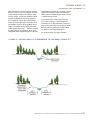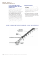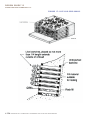
1
BANK PROTECTION/EROSION REPAIR DESIG N G U I D E
INTRODUCTION AND PURPOSE OF THE DESIGN GUIDE
This Design Guide is intended to clarify
the Chapter 1 of the Water Resources
Infrastructure Protection Manual, section
VIII, articles D-H (Outfalls, Pump stations
and Site Drainage). This Design Guide
describes how to address streambank
erosion problems, and how to use
bioengineered methods of bank protection
and erosion repair.
This Design Guide is to be used by local
permitting agencies, property owners
and professionals who design projects on
streamside parcels (i.e. civil engineers, land
use planners, landscape architects, etc..) It is
intended to:
• Provide guidance for how to design
a variety of bank protection projects,
in places where streambanks are, have, or
may be eroding
• Promote proactive approach to preventing
and resolving serious erosion problems
This document is a guide, not an instruction
manual. Erosion repair activities within a
stream channel will impact water quality,
flood protection, the stability of adjacent
properties, and the habitats of many streamdependant species. It is for these reasons
that these activities require several state and
federal permits, as well as the involvement
of qualified professionals to help design and
construct the project in a way that addresses
stability and long-term water resource
protection. Examples of more detailed
guidance manuals are listed at the end of
this document for reference.
MOVING TOWARD SOFT, MORE
SYSTEMIC METHODS OF BANK
PROTECTION/EROSION REPAIR
Traditional methods of controlling erosion
have relied on “hard” structural practices
such as covering banks with interlocking
concrete blocks and building retaining
walls. However, these techniques often
have negative impacts on streams. In many
cases, these methods are also expensive and
ineffective in the long run. Recommended
instead are “soft” or bioengineered bank
stabilization methods. A bioengineered
approach involves the planting of native
streamside or riparian vegetation combined
with the strategic placement of logs or
minimal rock, where necessary, and
regrading of steep slopes wherever possible
in order to produce living systems that
minimize erosion, control sediment, and
provide habitat. The natural attributes of
plants, when combined with stabilized
bank slopes, provide better dynamic stream
systems than stationary hard structures.
An objective of this Design Guide is to
protect, and where appropriate, restore
streambanks and related stream resources.
Where suitable, it encourages a systemic
approach to streambank protection and
stream restoration. This Design Guide
starts by describing how streams function,
typical features of a stream and importance
of riparian vegetation. It then discusses
typical causes of streambank erosion
and recommends basic measures to be
considered when planning and designing
a bank protection erosion repair project.
Finally, alternative methods of protecting a
streambank are presented, starting with how
to treat a reach of a stream in a more rural
setting where there is room to use a more
systemic approach, and continuing with
a variety of treatments for smaller, urban
parcels, which include a small reach of a
stream.
G OA L S / P U R P O S E O F
S T R E A M B A N K P R OT E C T I O N
AC T I V I T I E S
In general, the goals of any bank protection/
erosion repair activity should be to:
• Maintain or increase stream stability and
facilitate transport of sediment and water;
• Avoid localized solutions that repair
only a single erosion site but reduce the
stability of neighboring stream banks
USER MANUAL: GUIDELINES & STANDARDS FOR LAND USE NEAR STREAMS
4.65
D E S I G N G U I DE 19
GUIDE L I N E S A N D S TA N DA R D S I . V
and cause erosion problems on upstream
or downstream properties;
• Enhance and increase native vegetation
both in extent and diversity to provide
habitat value and help ensure long-term
bank stability.
With these goals in mind, this Design
Guide delineates some general guidelines
and issues to consider when embarking
on a bank-protection/erosion-repair
project, as well as a description of various
erosion-repair techniques. This guidance
also provides agency staff and streamside
property owners with a brief overview of
how streams are formed, their common
characteristics and features, and typical
causes of streambank erosion
4.66
USER MANUAL: GUIDELINES & STANDARDS FOR LAND USE NEAR STREAMS
DESIGN G U I D E 1 9
GUIDELINES AND STANDARDS I.V
ORGANIZATION OF THIS DESIGN GUIDE
This Design Guide is organized into two parts and six subsections. The Technical Primer part
includes useful background information that explains the causes of erosion. Homeowners
and project developers will likely refer to the Techniques and Guidance part more frequently,
because it outlines techniques and guidelines for erosion repair.
CONTENTS
PAG E
Part I: Technical Primer on Stream Function and Form
4. 68
Section 1: How Streams Function
4.69
Section 2: Typical Causes of Streambank Erosion
4.74
Part II: Techniques and Guidance for Developing Your Erosion Repair Project
4.76
Section 3: Embarking on a Bank Protection/Erosion Repair Project
4.77
Section 4: Introduction to Appropriate Watershed-Friendly Design
4.80
Section 5: Detailed Descriptions of Erosion Repair Techniques
4.83
Section 6: Helpful Hints on Obtaining Permits for Stream-bank Repair
4.110
Section 7: Reference Materials
4.116
USER MANUAL: GUIDELINES & STANDARDS FOR LAND USE NEAR STREAMS
4.67
B A N K P R OT E CTION/EROSION R EPAIR DESIGN GUIDE
PART ONE : TECHNICAL PRIMER ON STREAM
FUNCTION AND FORM
4.68
USER MANUAL: GUIDELINES & STANDARDS FOR LAND USE NEAR STREAMS
DESIGN G U I D E 1 9
GUIDELINES AND STANDARDS I.V
SECTION 1 - HOW STREAMS FUNCTION
I NTRODUCTION
Before considering bank protection or
erosion repair, it is necessary to understand
the process by which streams form and
adjust to their surroundings. Streams are
shaped by a combination of “forming
forces” that include:
• Gravity, or the slope of the channel banks
• Friction, which is a function of vegetation,
the soil’s type and particle size, and the
channel’s pattern and profile.
• Velocity, the speed of the water flow.
• Quantity, the volume of water flowing
and sediment moving through the stream.
Over time, streams move and shift in
response to changes in these forming forces.
That is why streams do not naturally tend to
flow in a straight line. Instead, they meander
in search of equilibrium with their forming
forces, adjusting to changes in water flow
and sediment transport. These changes can
have both natural and non-natural causes.
CHARACTERISTICS AND
HISTORY O F STREAMS IN
S ANTA CLARA COUNTY
Some streams in Santa Clara County are
still in a natural condition, while others
have been straightened or channelized in
response to land development activities and
flood control needs. Throughout the County,
human-made channels were created to
contain the flows that once naturally fanned
out over the valley floor, carrying with them
nutrients and sediment, and creating alluvial
fans and fresh water marsh habitat. These
human-made channels were created to
accommodate the use of land for agriculture
or urban development, and to ameliorate
flooding conditions.
Experience has also shown, however, that
significant problems arise when streams
in the lower watershed are confined. By
lining streams with levees or floodwalls,
water that would otherwise slowly spread
out over a large area of land in a beneficial
way accumulates in the channel until it
breaches its levee or floodwall, potentially
causing catastrophic flooding. Even if this
does not happen, a significant amount of
sediment may be deposited in the channel
after a storm event, raising the channel
bed elevation. This sediment decreases the
channel’s capacity to handle subsequent
storm flow. In other words, the chance of
catastrophic flooding increases with every
storm if the channel’s sediment is not
removed often enough.
Significant efforts are underway throughout
the County to address these issues, and
to maintain and enhance our remaining
natural streams. There are also efforts
being made to restore and enhance, where
possible, channelized urban drainage
ways. It is important to remember that
even though a stream may be hardened
or modified in a particular location, it may
remain natural in other areas. Over time,
it may be possible and even essential to
restore these streams to a more natural
state to improve stability and flood
protection for nearby property owners.
In addition, the protection of water quality
is critical in all types of Santa Clara County
streams, both natural and unnatural,
because they eventually convey water to
either Monterey Bay or San Francisco Bay.
USER MANUAL: GUIDELINES & STANDARDS FOR LAND USE NEAR STREAMS
4.69
D E S I G N G U I DE 19
GUID E L I N E S A N D S TA N DA R D S I . V
TYPICAL STREAM FEAT U R E S
In a cross-sectional view, a stable natural
stream can be defined by two significant
features: the “bankfull” (or “active channel”)
and the “active floodplain.”
See figure 1 below.
The bankfull or “active channel” can be
defined by the elevation of the floodplain,
which is formed by the most effective
channel forming or “dominant” stream
discharge. It is the part of the stream
where sediment is actively transported
and deposited, the part that is capable of
containing the most frequent flows.
The active channel is an important feature
because it transports the majority of the
water and sediment in the stream system,
and thus it influences the channel formation
over time. As seen in Figure 1, the active
channel is usually distinguished from the
active floodplain by an abrupt change in
the slope of the stream bank, usually from
a vertically-sloped plane to the horizontallysloped plane on top of the floodplain.
Active floodplains are the low-lying areas
between Top of Bank (See Figure 1) and
adjacent to the active channel that are
subject to frequent inundation during
moderate and high flows. This area is where
sediment is deposited when the active
channel’s capacity is exceeded during high
flows. In urban settings, active floodplains
are often hard to identify, due to channel
incision and erosion from increased
urban runoff. On rural streams, the active
floodplain normally fills approximately every
year or two. Floodplain filling usually occurs
more often in urban areas. Vegetation is
typically present in the floodplain area,
as it will become established between the
alternating seasonal periods of inundation
and sediment deposition.
(Section 2 of the Guidelines and Standards
also includes more detailed definitions and
sketches showing these features in a variety
of settings).
Important Note: A stream’s active floodplain
is not to be confused with the delineation
of floodplain used for flood insurance
purposes. The floodplain defined for flood
insurance purposes is the one percent
(100-year) flood, or the area that has a
one percent chance of being flooded to
a depth of one foot or greater each year.
For insurance purposes, this equates to a
26 percent chance of suffering some flood
damage during the term of a 30-year
mortgage.
FIGURE 1: CROSS - SE C T I O N A L V I E W O F A N AT U R A L S T R E A M
4.70
USER MANUAL: GUIDELINES & STANDARDS FOR LAND USE NEAR STREAMS
DESIGN G U I D E 1 9
GUIDELINES AND STANDARDS I.V
STREAM BELTWIDTH AND
STREAM MEANDER WIDTH
A channel has a certain beltwidth within
which it naturally moves. This beltwidth can
be determined by studying: sections of the
channel which have not been straightened;
pre-development photographs; or, adjacent
similar channels. Levees should not, for
example, be constructed in a way that does
not accommodate the beltwidth. Doing
otherwise increases erosion potential and
maintenance costs.
Meander width is the amplitude of the
meander within the beltwidth. It is smaller
than the beltwidth. At a minimum, the
average meander width of a channel should
not be compromised in the lower flood
plains. In the mid to upper slopes above the
valley floor, where the natural channel may
be fairly straight, the beltwidth should also
be respected.
FACTORS THAT AFFECT STREAM
STABILITY
Several factors affect stream stability. They
include stream topography, the width-todepth ratio, and extent of channel incision
The quantity and movement of both water
and sediment in a stream are two of the
primary influences on the topography of
a stream. These materials tend to balance
each other within the confines of the stream
channel. For example, erosion on one bank
is typically balanced by sediment deposition
on the other. While the location and extent
of the erosion and resulting deposition may
change over time, the width and depth of a
stable stream does not change much. Thus,
any type of erosion repair project must be
designed to maintain width-to-depth ratio in
order to ensure long-term stream stability,
while also allowing the streambed to erode
and fill naturally.
A channel’s width-to-depth ratio is
calculated by dividing the width of the
stream channel (at the bankfull level) by the
mean channel depth. Width-to-depth ratio
is part of a more complicated concept called
entrenchment ratio, which is important
because it calculates a channel’s stability.
Generally speaking, it calculates its stability
in terms of its floodplain—the larger the
floodplain, the higher the entrenchment
ratio. Specifically the entrenchment ratio is
equal to the width of the stream channel
(at twice the maximum bankfull depth)
divided by the width-to-depth ratio of
the bankfull channel. In order to prevent
channel incision and maintain a stable
stream, the ratio of the width of the channel
at 2 bankfull heights (see Figure 2) to the
bankfull width should be a minimum of 2
where the channel is constrained. It should
be a 3 to 4 ratio at other locations, both
upstream and downstream. This provides
sufficient relief, and thus prevents excessive
erosion of streambed and bank. It also
prevents damage to bankside properties
during 1 year–10 year storm events.
FIGURE 2. DETERMINING THE A P P R O P R I AT E W I D T H TO D E P T H R AT I O
USER MANUAL: GUIDELINES & STANDARDS FOR LAND USE NEAR STREAMS
4.71
D E S I G N G U I DE 19
GUID E L I N E S A N D S TA N DA R D S I . V
EFFECTS OF WATER A N D
SEDIMENT TRANSPOR T O N
BANK STABILITY
Finally, because armored banks cannot
adjust to changing stream conditions, they
are prone to undercutting.
Streams adjust themselves to transport, as
efficiently as possible, water and sediment
from higher elevations to lower elevations.
If the amount of sediment available to a
creek is significantly increased or decreased,
the creek adjusts its channel area or cross
section to handle the change in sediment.
In a normally-functioning gravel bed stream,
for example, it is not uncommon for the
stream channel (or portions of the stream
channel) to downcut and refill significantly—
from a few inches to 10 feet or more in a
single storm event. This is one way streams
transport their sediment loads, clean
themselves, and temporarily increase their
flow capacity.
I M P O R TA N C E O F V E G E TAT I O N
A N D R I PA R I A N B U F F E R S
With the expanded development in Santa
Clara County, the time it takes for runoff
to reach the streams has decreased, which
leads to the increase in the amount of water
in most streams. Some of the specific
factors that have led to this increase in water
flows are:
• Substantial increases in impervious
surfaces such as pavement and roof tops.
• The routing of storm water runoff directly
into streams through piped storm drain
systems.
• Removal of large areas of streamside
vegetation that would otherwise form
buffers for runoff, and promote infiltration
into the soil.
The stormwater management programs of
local municipalities have efforts underway
to address these long-term issues. In
the interim, however, it is important that
armoring the channel be avoided on
individual properties whenever possible,
for several reasons. First bank armoring
prevents channels from adjusting to high
flows, and can increase the probability
of flooding. Bank armoring also causes
accelerated flow velocities and turbulence
along banks, which then induces more
erosion on unarmored banks.
4.72
The roots of well-established vegetation not
only protect the surface of stream banks,
but also penetrate deeply into the ground,
helping to stabilizing it. Lack of vegetation
close to a creek bank can contribute to
slope instability and failure due to overbank
drainage or soil saturation. In addition
to providing bank stability, streamside
vegetation filters pollutants; shades and
cools the stream; increases infiltration;
reduces flash runoff; and provides habitat
for wildlife. A variety of scientific studies
of the minimum and optimum width of a
vegetated buffer along a stream indicate
that a width of 10 feet is not enough to
provide adequate filtration or habitat. A
study by U.S. Fish and Wildlife indicates that
in order to effectively remove pollutants, a
buffer of 50 feet is needed. Other sources
recommend a vegetated buffer that is 2 to
5 times the width of the stream channel.
While there is ongoing discussion about
the most appropriate width for vegetated
buffers, it is conclusive that at least some
adequate buffer is necessary to protect
stream resources. In terms of erosion repair
projects, the use of live plants, either alone
or in combination with dead or select rock
materials, can be sufficient to prevent
erosion, control sediment, and provide
habitat.
S T R E A M F E AT U R E S T H AT A R E
I M P O R TA N T TO F I S H H A B I TAT
The movement of water through a
streambed creates certain natural
characteristics or that benefit fish habitat.
Some of these important features are riffles,
runs, glides and pools. Riffles are located in
shallow areas or bends in a stream where
water flows over rocks. Runs are the straight
sections between riffles. Glides are the
transition areas between the downstream
end of pools and a run or riffle. Pools are
usually formed on the outside of bends in a
USER MANUAL: GUIDELINES & STANDARDS FOR LAND USE NEAR STREAMS
DESIGN G U I D E 1 9
GUIDELINES AND STANDARDS I.V
stream. Deep pools are particularly import
ant in providing critical fish habitat and
refuge areas. When the flow in the stream
decreases in drought, fish can retreat to
these pools to wait for the return of higher
flows.
These stream features described above
differ from stream to stream depending
on a stream’s geometry and location. For
example, at higher elevations, stream
channels are steeper, narrower, and drop
at faster rates, and may contain series of
step-pool cascades. At a lower elevation,
however, a channel tends to be less steep,
wider, and more sinuous, making riffles and
pools more common. The combination of
riffles, runs and pools is extremely important
for fish because it provides different feeding,
spawning and/or nursery areas. These
stream characteristics should be preserved,
restored, and enhanced where possible, as
appropriate to the stream topography, in
any type of erosion repair effort.
USER MANUAL: GUIDELINES & STANDARDS FOR LAND USE NEAR STREAMS
4.73
D E S I G N G U I DE 19
GUID E L I N E S A N D S TA N DA R D S I . V
SECTION 2 - CAUSES OF STREAM BANK EROSION
All streams erode to some extent as a part
of natural processes. Natural erosion is
typically caused by:
1) Hydraulic forces that remove bank
material;
2) Geotechnical instabilities;
3) Or, most commonly, a combination of
both these two forces.
HYDRAULIC FAILURE S
Hydraulic failures occur when the force or
velocity of the water is greater than the
natural cohesion of the soil. In other words,
the forces that bind the soil together are
overcome by the water. Some visible features
of hydraulic failures are erosion near the
bottom, (or at the “toe,”) of a stream bank,
or alteration of the streambed. Changes in
the direction of flow, constrictions, increases
or decreases in the amount of sediment, and
increased amount and duration of flow from
impervious areas can all accelerate erosion
of the stream bank or alteration of the
streambed, and in turn, hydraulic failure.
Some of the sediment that is introduced
into the stream will naturally deposit on
the bottom of the stream. Over time, this
may raise the bottom of the stream and
reduce the capacity of the active channel,
forcing the water to spread out laterally.
This causes erosion and steepening of the
stream banks. This can also occur when a
stream is starved of sediment (typically by
dams or erosion control structures) and the
excess energy that would have been used to
transport sediment is now free to erode bed
and banks. This condition typically occurs
with the construction of hardened channel
linings, or with the addition of other types
of instream debris, sediment, or detention
basins that trap sediment. In this case, the
erosion (down-cutting and steepening) of
the streambed and banks occurs below
the lined section (or “instream basin”),
causing the eroded sediment to settle farther
downstream. Nonetheless, the impact on the
stream is similar. Thus, for hydraulic failures,
4.74
the most effective erosion repairs are
accomplished by addressing the root cause
of the failure, which may include installation
of measures to redirect flow, increasing the
erosion resistance of the bank, by planting
vegetation on the bank or adding protection
to the toe of the stream bank.
G E OT E C H N I C A L FA I L U R E S
Geotechnical failures occur when
gravitational forces are greater than the
strength of the soil. These failures are
usually caused by over steepened banks
and/or excess moisture in the soil. This
results in the movement of earth, better
known as a landslide. Near a stream, the
likely causes of this type of failure are a
high groundwater table, poorly designed
surface drainage systems (such as those that
drain surface runoff directly over the top of
the stream bank), leaking swimming pools,
and leaking septic systems or water lines
(which saturate the stream bank). Thus, for
most geotechnical failures, what must be
addressed is the source of the water that’s
causing excess moisture in the vicinity of the
stream bank.
C O M B I N AT I O N FA I L U R E S
The third type of failure is a combination
of hydraulic forces and geotechnical
instabilities. Hydraulic failures often lead
to geotechnical failures. As the toe of the
stream bank erodes, or the channel cuts
downward because of hydraulic forces,
the bank effectively increases in height
and becomes too steep and unstable.
Sometimes, the upper portion of the
stream bank fails from lack of support, and
slides into the stream. This process is well
described in the document Maintaining
Corte madera Creek: A Citizen’s Guide to
Creek-side Property Protection, which was
prepared by Phil Williams and Associates
in Collaboration with H. T. Harvey and
Associates for the San Francisquito Creek
Joint Powers Authority. They write, “The
higher a bank is, the flatter the angle must
be to prevent slumping. For example, most
USER MANUAL: GUIDELINES & STANDARDS FOR LAND USE NEAR STREAMS
DESIGN G U I D E 1 9
GUIDELINES AND STANDARDS I.V
soils will support a three-foot high vertical
bank, but if the river cuts a deeper channel
(say five feet) the bank will collapse under
its own weight. A five-foot tall bank would
need to be graded to a lower gradient to
be as stable as a three-foot vertical bank,
and a ten-foot high bank would have to be
excavated to an even lower gradient to be
stable. The higher the bank, the lower the
stable gradient becomes.” The best remedy
for this problem—the problem of an oversteepened bank experiencing both hydraulic
and geotechnical failures—combines several
steps. The first step involves regrading the
slope to a more stable angle, which is why it
is called “laying it back.”
The second step involves reinforcing the
toe, where necessary, with biotechnical
methods such as logs and rocks. The third
step involves reducing erosive energy on the
bank by planting the bank, so that it does
not become over-steepened again.
For an illustration, see figure 3 below.
FIGURE 3: LAYING BACK A STR E A M B A N K TO I N C R E A S E S TA B I L I T Y
USER MANUAL: GUIDELINES & STANDARDS FOR LAND USE NEAR STREAMS
4.75
B A N K P R OT E CTION/EROSION R EPAIR DESIGN GUIDE
PART TWO :
TECHNIQUES AND GUIDANCE FOR DEVELOPING
A WATERSHED -FRIENDLY EROSION REPAIR PROJECT.
4.76
USER MANUAL: GUIDELINES & STANDARDS FOR LAND USE NEAR STREAMS
DESIGN G U I D E 1 9
GUIDELINES AND STANDARDS I.V
SECTION 3 - EMBARKING ON YOUR BANK
PROTECTION/EROSION REPAIR PROJECT
This section describes five initial steps to
consider in undertaking an erosion repair
project. This text borrows extensively from
the guidance manual developed for the
Guadalupe and Alamitos Creeks entitled
“Stream-bank Repair Guidance Manual for
the Private Landowner,” which is cited in the
references section.
I NITIAL STEPS
Step 1: Establish the Purpose and Necessity
of Your Project
Step 2: Hire Qualified Professionals
Step 3: Get to the Root of the Problem
Step 4: Seek Assistance from the Water
District
Step 5: Secure Permits from the Appropriate
State and Federal Agencies
S TEP 1. ESTABLISH THE
PURPOSE AND NECESSITY OF
YOUR PROJECT
Repairing a stream or bank erosion problem
is not a simple or routine task. The root
cause of the bank failure must first be
identified. Then, the most probable stable
channel form and dimensions must be
determined, based on geomorphology and
hydrology, as well as hydraulic analyses.
Only then can a proper solution or repair be
recommended.
Before embarking on any bank stabilization/
erosion repair project, it is important to
answer the following questions: What is
the purpose of this project? What are its
objectives? Is it necessary?
Some examples of objectives could include:
• Protecting property or structures
• Restoring eroded banks
• Protecting existing banks from erosion
• Restoring riparian habitat and improving
stream function
Determination of the project’s necessity must
take into account the fact that some erosion
is natural and acceptable. For example, the
exposure of roots on a streamside tree is
natural, and unless extreme, it will not hurt
the tree. If the bank height is less than about
eight feet, what is easily perceived as bank
erosion may be only temporary, or even
reverse itself as the stream meanders in its
floodplain. Some erosion repair activities,
such as bank armoring, can destabilize
other areas erosive forces are transferred
downstream, or onto opposite banks,
eventually causing additional problems. A
qualified professional may be needed to
help determine whether, and to what extent,
erosion is in need of repair.
S T E P 2 . H I R E A Q UA L I F I E D
E X P E R T TO D E T E R M I N E T H E
A P P R O P R I AT E D E S I G N
Designing an erosion repair project that
maximizes stability and avoids unintended
consequences is complicated. As noted
earlier, a stream must have a properly
dimensioned bankfull channel in order for
it to have long-term stability. Other critical
factors in proper channel design include:
proper width to depth ratio, water velocity,
sheer stress, and channel slope. Most
property owners do not have the training
or expertise necessary to incorporate all of
these considerations into project design.
A walk along many Santa Clara County
streams proves this point. It reveals many
examples of how individual property owners,
without professional help, tried to control
streambank erosion by armoring the bank.
These measures often fail to address the
need to reduce shear stresses in order
to keep the bed and banks from eroding.
Eventually, the channel will downcut, and
in most cases, fail. Professionals can help
avoid this kind of failure-prone approach
to streambank repair and help identify and
address the root cause of the problem.
USER MANUAL: GUIDELINES & STANDARDS FOR LAND USE NEAR STREAMS
4.77
D E S I G N G U I DE 19
GUID E L I N E S A N D S TA N DA R D S I . V
STEP 3. IDENTIFY TH E S O U R C E
OF THE PROBLEM
It is important to identify and, if possible,
address that the source of streambank or
bed erosion. If it is not addressed, the
erosion repair project may either need to
be repeated or expanded in the future, or
cause other erosion problems upstream,
downstream, or across the stream. To
identify a potential source, one should look
for:
• Flow constrictions like bridges or debris
that increase downstream velocities and
shear stress,
• Existing hardscape, or paved over
areas, that may be increasing velocities
downstream,
• Natural or non-natural debris that may
have redirected the flow into the bank,
• Drainage features that may be directing
flow onto, or saturating, the bank,
•Watershed-wide increases in amount and
duration of runoff that may be causing
systematic degradation of the creek
channel (incision), which leads to toe
failures and bank slumps.
These underlying causes of erosion could
be natural features or constrictions, but
most likely, they are non-natural, i.e.,
human-made. Oftentimes, the source of the
problem is an earlier effort to address an
erosion problem upstream or downstream.
Depending on the extent of the problem, it
may be worthwhile for the property owner to
consider a collective effort with neighboring
property-owners, perhaps even including
government and/or public agencies who
own land or rights-of-way in or near the
stream.
Because actions taken to address erosion in
one place can cause problems elsewhere,
permit applicants should consider the
potential impacts on both the downstream
and upstream streambed and banks when
determining the type of erosion repair
measure to use. To this end, property owners
may be asked to provide professional
analyses of stream geomorphology and/or
4.78
hydraulics to determine potential negative
impacts, and recommend ways to prevent
them.
S T E P 4 . S E E K A S S I S TA N C E
F R O M T H E S A N TA C L A R A
VA L L E Y WAT E R D I S T R I C T
(SCVWD)
For SCVWD’s assistance in conducting
repair or maintenance, contact the SCVWD’s
Watershed staff at 408.265.2600. There
are three different scenarios related to
ownership and easement that determine
assistance eligibility:
S C V W D R I G H T O F WAY: If the
District owns the property where the stream
is located, District staff will visit the site to
inspect the erosion, determine if and how it
should be addressed, and then, if need be,
take appropriate measures to do so.
S C V W D E A S E M E N T: If the District
has an easement on the section of the
stream needing repairs, District staff will visit
the site to inspect the erosion. Easements
generally provide the District with the
necessary rights to perform the work.
The District can make repairs within an
easement after assessing the extent of the
erosion, the infrastructure affected, the
available funding, and the need to conduct
other work on District property.
PR IVAT E O W N E R S H I P: If the stream
is under private ownership, District staff is
generally available for a visit to the site,
however this availability will depend on
the number of requests received and staff
resources. Staff can provide advice on an
approach to use but, the District will not
design or construct the project.
Requests for technical assistance for minor
erosion repair work can be submitted to
the District via their web site at http://
www.valleywater.org/Water/Watersheds__streams_and_floods/Taking_care_of_
streams/Service_request_form.cfm. To
negotiate an agreement for assistance on
a substantial repair project, contact the
District’s Watershed staff at 408.265.2600.
USER MANUAL: GUIDELINES & STANDARDS FOR LAND USE NEAR STREAMS
DESIGN G U I D E 1 9
GUIDELINES AND STANDARDS I.V
STEP 5. SE CURE PERMITS
FROM FEDERAL , STATE AND/OR
LOCAL RESOURCE AGENCIES
Most erosion repair projects will require
permits from federal, state and/or
local regulatory agencies if they entail
construction between the banks of a stream.
Please refer to the Resource Agency Referral
List in Section 6 of this Design Guide
for a list of all the agencies, the types of
activities for which they should be contacted,
and their contact information. The San
Francisco Bay Area Joint Aquatic Resource
Permit Application (JARPA) consolidates
the information that permitting agencies
require into a single application. The JARPA
application can be found at:
http://www.abag.ca.gov/bayarea/sfep/
projects/JARPA/JARPA.html
The permitting process can take as little as
a few weeks to complete, but typically takes
a few months, depending on the complexity
of the project and the presence (or
potential presence) of federal of state listed
endangered, threatened or special status
species of plants or animals. Typically, the
U.S. Army Corps of Engineers, the Regional
Water Quality Control Board, and California
Department of Fish and Game will issue
permits under federal and state laws, while
the Santa Clara Valley Water District or the
local municipality acts as the local permitting
agency.
I MPORTANT NOTE : Bank repair
designs that avoid or minimize hardscape
and are based on sufficient analysis of
the cause of failure and stable channel
characteristics almost always receive permits
more readily than those that do not. Do not
hesitate to contact agency representatives
early in the design process to determine
whether you need a permit from their
agency, and to discuss potential repair
options if you do.
USER MANUAL: GUIDELINES & STANDARDS FOR LAND USE NEAR STREAMS
4.79
D E S I G N G U I DE 19
GUID E L I N E S A N D S TA N DA R D S I . V
SECTION 4 – GENERAL GUIDANCE FOR
WATERSHED FRIENDLY DESIGN
USE VEGETATION TO R E S TO R E
AND MAINTAIN STAB I L I T Y
Revegetation of the streambank is one of the
most common, and often the most effective,
way to prevent erosion along a streambank.
This is because roots bind soils together,
which prevents erosion, while leaves provide
protection from rain splash erosion. In
addition, the exposed trunks and stalks
provide resistance to stream flow because
they slow the water and decrease its erosive
energy. An added benefit is that vegetation
provides ideal habitat for birds and other
animals. Vegetation planting methods
commonly used include cuttings, transplants,
live staking, and direct seeding (including
hydro-seeding).
• Maintain streamside trees. Avoid pruning
trees unless it is necessary to the survival
of the plant or the protection of existing
property and/or infrastructure as trees can
critical shelter and shade for stream
wildlife.
• Do not remove affixed logs. Logs that have
been permanently or securely affixed to
the streambank provide valuable habitat.
Their removal could negatively impact
fish habitat, and might therefore require
mitigation. However, downed trees and
logs can often deflect high flows, causing
serious bed and bank erosion, destroying
fish habitat, and degrading water quality.
For these reasons, downed trees and logs
need to be removed quickly.
• Plant between October 15 and March
15. In order to minimize irrigation
requirements and ensure that plants
receive sufficient water for natural
propagation, plant in the fall and early
winter. Where soils are dry and water
is limited, irrigate as needed until the
rainy season.
• Do not introduce invasive non-native
vegetation species into the watershed.
Non-native invasive plants are a
4.80
serious problem because they often
inappropriately constrict water flows and
overtake native plant species.(See Design
Guide 2 for more on invasive
non-natives).
• Instead, use locally collected native
species for revegetation and replacement
plantings. Plant selection and density
should be informed by a survey of
natural areas on the same creek that
have a similar ecological setting. This
can inform you as to what species would
be found in the area and an approximate
population density. See Design Guide 4
and 5.
• Plant according to moisture needs,
using different types of vegetation on the
upper and lower sections of the stream
bank. Plants have different tolerances for
the wet conditions at the toe of slope.
They also vary in drought-tolerance
and erosion-control effectiveness on
the upper slopes. Some tree species,
such as willows and cottonwoods, are
more successful when they are closer to
the stream. Others, like oaks, enjoy more
success higher up the bank. Where stream
capacity is an issue for flood protection
purposes, choose vegetation that is
flexible and that will not collect debris and
slow high flows during flood events.
• Use fast-sprouting grass species for more
immediate erosion control. A regraded
slope can be seeded with fast-sprouting
grass species such as sterile wheat, or
better yet, a native grass/sedge seed mix
combined with a biodegradable erosion
control blanket. These species provide
more immediate erosion control.
See Design Guides 4 and 5 for plant
species.
• Do not use chemical fertilizers, herbicides
or pesticides. These chemicals can be
easily transported to the creek by
wind or rain and degrade water quality,
endangering aquatic life.
USER MANUAL: GUIDELINES & STANDARDS FOR LAND USE NEAR STREAMS
DESIGN G U I D E 1 9
GUIDELINES AND STANDARDS I.V
WATERSHED -FRIENDLY DESIGN: BEST
MANAGEMENT PRACTICES
This section provides some tips for stream
care during construction. Proper use of best
management practices (BMPs) can have a
tremendously beneficial impact on aquatic
species and other wildlife, human health,
environment, property, and public services.
C ONSTRUCTION BMPS :
• When restoring a damaged section
of a streambank, imitate natural
stream features, such as channel
meanders, appropriate width and depth,
and vegetation. This will stabilize the
channel. Details of this concept are
included in Section 5 of this Design Guide.
• Observe work windows. In-channel
work should generally be conducted
during the dry season, between
June15th and October 15th, to
minimize negative impacts to plant
and wildlife. Sometimes these dates will
vary depending on the wildlife species
in the area. Do not use heavy equipment
during spawning or migration seasons,
as it can destroy fish habitat.
If construction during periods of stream
flow can not be avoided, include measures
to separate area of disturbance from
stream flow to minimize turbidity
in stream.
• Avoid removing in-stream gravel.
Avoid disturbing the creek bed,
particularly spawning gravel. After project
completion, replace or restore any gravel
that was moved or removed to maintain
spawning areas for fish.
• Take special care when establishing
stream access points, because these points
can contribute undesirable sediment to the
stream. So
• Use established access point
wherever possible.
to the work area as possible in
order to minimize adverse
impacts. When the project is
complete, restore the access Point
to as natural and stable
condition as possible.
• Prevent soil at construction
entrances from being
tracked onto streets near
work sites.
• Control dust. Dust can be a nuisance,
and have an adverse impact
on water quality.
To control dust:
• Water active maintenance areas
so that they are sufficiently moist
to prevent dust.
• Sweep any paved access roads of
visible soil material.
• Cover trucks hauling sediment,
ensure that their tailgates are
closed, and brush off any
excess dirt.
• Store and secure materials.
Remove all building materials, debris,
lumber, et cetera within 2 days of
completing the project.
• Be wary of mercury and other
contaminants. Disturbed or excavated
soils in areas where soils are known to
contain mercury or other contaminants
should be removed or properly capped
if the soil will be exposed to flood flows.
In areas whose soils are known to
contain mercury, remediate the disturbed
or excavated soils if they are exposed to
flood flows. Wear protective equipment.
Consult the Santa Clara Valley Water
District for disposal guidance.
• If it is necessary to create
a temporary access point for
construction, do so as close
USER MANUAL: GUIDELINES & STANDARDS FOR LAND USE NEAR STREAMS
4.81
D E S I G N G U I DE 19
GUID E L I N E S A N D S TA N DA R D S I . V
FOLLOW-UP MAINTE N A N C E :
Do not neglect stream-bank repair after
construction is over. Minor maintenance
activities help ensure a project’s success.
• Remove trash and debris. Sometimes,
the accumulation of debris in the channel
causes erosion on nearby banks. So:
• Revegetate. In areas that have been
revegetated, replace dead or dying plants
and weeds. Remove non-native plant
colonizers. Ensure that all plants receive
sufficient water.
•Regularly remove debris such as
trash and human-caused debris.
• Do not put yard waste in the
creeks or on the banks, where
leaves and clippings
can wash into the stream.
•If mulching:
• Use biodegradable erosion
control blankets on bare
slopes or if it is too late
in the season to establish
vegetation. The blankets
will last for 1 to 3 years
while natives reseed.
Monitor the success of natural
revegetation before taking
aggressive action to revegetate.
• Woody debris from the site might
make for suitable mulch.
• Use bark and other wood products
or fabric blankets above the high
water line to prevent erosion of
bare soil after construction
is completed.
• Use weed-free certified mulch.
• Do not use Eucalyptus, Walnut,
or Tree of Heaven. They produce
an allelopathic compound that can
be toxic to plants and aquatic
organisms.
• Be careful when trying to control
rodents. Burrowing rodents may
be a nuisance and can damage levees on
streams, but do not use rodenticides.
Their effect on the local habitat is too
destructive. Instead, consult County
Vector Control.
4.82
USER MANUAL: GUIDELINES & STANDARDS FOR LAND USE NEAR STREAMS
DESIGN G U I D E 1 9
GUIDELINES AND STANDARDS I.V
SECTION 5 - DETAILED DESCRIPTIONS OF
EROSION REPAIR TECHNIQUES
Described in this section are 16 different
types of erosion repair methods. Each
description contains a brief overview of
the repair method, the circumstances in
which it is most appropriate, its anticipated
environmental value, its relative costs,
and its potential impacts. Descriptions are
not exhaustive, and should only be used
in conjunction with consultation from a
qualified erosion repair professional, the
Santa Clara Valley Water District, and
relevant regulatory agencies.
Even the most well-meaning erosion repair
designs can have negative impacts on a
stream if they are not planned, designed,
and constructed properly. Poorly placed
rocks or woody material can cause bed and
bank scour/erosion, excessive sediment
deposition, and/or decreased channel
capacity. For this reason, it is essential that
the project is designed to accommodate
the site’s particular geomorphic location,
channel form and depth, flow velocity, and
site constraints. This typically requires a
physical, or “geomorphic” assessment by a
trained professional.
To protect both your property and its value,
the goals of any streamside bank protection
or erosion repair project should be to
restore stability and leave the site in a better
ecological condition than it was before.
The first erosion repair method, the modified
flood plain, will provide the best long term,
ecologically friendly and most stable results.
Methods 2 through 8 use bioengineering
methods. Bioengineered bank stabilization
methods typically involve two components:
If soft methods of protection are not feasible
due to highly erosive forces, then there is
probably a channel dimension, hydrology
and/or morphology problem.
Hard bank protection can cause more
erosion and damage in the channel, along
the downstream and/or upstream banks,
as well as on the opposite bank of the
repair site. Any consideration of the use of
hardened materials should be with caution
and with an assessment of the impacts that
may occur.
Erosion repair methods 9 thorough 11,
incorporate bank armoring which should
be avoided. The use of log and rock
flow deflecting structures as described in
method 1 is less expensive and a more
environmentally friendly way of protecting
banks from erosion. Detailed guidance of
these methods is beyond the scope of this
Design Guide but should be considered by
the design professional.
Erosion repair methods 12 through 16 are
NOT recommended. However, they may
be necessary when the site is constrained,
or where the water volume, velocity, bank
steepness, and resultant erosive forces
necessitate the use of more extreme
methods
• Regrading the upper streambank to
establish or re-establish a floodplain,
with terraces where possible.
• Planting native riparian vegetation on
the streambank and terraces in order to
restore and provide long-term stability.
USER MANUAL: GUIDELINES & STANDARDS FOR LAND USE NEAR STREAMS
4.83
D E S I G N G U I DE 19
GUID E L I N E S A N D S TA N DA R D S I . V
TAB L E 1 : P R E F E R R E D E R O S I O N R E PA I R M E T H O D S
Repair Method
1. Modified
floodplain
2. Slope Grading
with Vegetation
Appropriate Slope
Appropriate Water Velocity
Environ Value
Cost
Varies
Varies
Positive
Low
2:1 or flatter for vegetation Low – typically up to 6 ft/sec
section, 1.5:1 or flatter for
boulder section.
Positive
Low
Generally 1-7 ft/sec but can go
2:1 or flatter for erosion
mat section, 1.5:1 or flatter up to12ft/sec if vegetated.
if boulders used.
Low
Positive, if planted. Low
Positive
Low
Low
2:1 or flatter for erosion
mat section, 1.5:1 or flatter
if boulders used.
2:01 Medium
Positive
Low
Positive
Low
Up to 1:1
Medium
Positive
Low
8. Root wads and
boulders
Medium: (10 ft/sec or less)
Positive, if planted High
9. Boulder/ Rock Up to 1:1, preferably 2:1.
Revetment
Medium
High: up to 15 ft/sec; less where Negative.
voids in boulders are planted.
Negative to
Neutral, if planted
10. Cellular
Confinement
System
Medium to High:5-21 ft/sec
depending on vegetation)
Neutral
Medium: up to 12 ft/sec or less
Neutral to High, if High
planted
3. Erosion Mats
4. Contour
Wattling
5. Brush
Mattresses
6. Brush Layering
7. Vegetated
Geogrids or Soil
Lifts
Up to 0.5 to 1
11. Live Log Crib Up to 0.25:1
Walls
4.84
USER MANUAL: GUIDELINES & STANDARDS FOR LAND USE NEAR STREAMS
Medium
DESIGN G U I D E 1 9
GUIDELINES AND STANDARDS I.V
#1 MODIFIED FLOODPLAIN
HOW TO CREATE A MODIFIED
FLOODPLAIN
The modified flood plain design provides the
optimum solution for long-term, ecologicallyfriendly, and less expensive stability. In
urban areas property owners typically have
short stretches of stream running through
their property and often only on one side
of the stream. The cooperative enlisting
of neighbors to affect this approach is
well worth the effort. The typical steps in
creating a modified floodplain are:
Step 1: Identify the appropriate channel
width and depth, at bankfull level. The active
channel will contain flows resulting from
small frequent rainfall events.
Step 2: Identify the appropriate elevation
for the floodplain area, and determine how
much space is available and appropriate for
widening the banks.
Step 3: Regrade or lay back the existing
bank above the floodplain to a flatter, more
stable angle (usually a 2 horizontal to 1
vertical slope, or greater);
Step 4: Create terraces above the active
floodplain to accommodate vegetation
Step 5: Plant the terraces with appropriate
local, native, riparian vegetation to stabilize
the bank(s) and create habitat.
USER MANUAL: GUIDELINES & STANDARDS FOR LAND USE NEAR STREAMS
4.85
D E S I G N G U I DE 19
GUID E L I N E S A N D S TA N DA R D S I . V
HOW TO CREATE A M O D I F I E D F LO O D P L A I N I N D E E P LY I N C I S E D
CHANNELS
A watershed-friendly design that recreates a natural floodplain is depicted
in Figures 4 and 5 below:
FIGURE 4: STREAM C H A N N E L W I T H D E E P LY I N C I S E D S T R E A M B A N K S
FIGURE 5: THE SAME S T R E A M C H A N N E L A S F I G U R E 4 , B U T S T R E A M
BANKS HAVE BEEN R E G R A D E S TO C R E AT E T E R R AC E S W H E R E
VEGETATION CAN BE P L A N T E D
4.86
USER MANUAL: GUIDELINES & STANDARDS FOR LAND USE NEAR STREAMS
DESIGN G U I D E 1 9
GUIDELINES AND STANDARDS I.V
H O W T O C R E AT E A M O D I F I E D
F L O O D P L A I N I N B R O A D F L AT
STRETCHES WITH SEDIMENT
DEPOSITION
In some cases, a stream may have
experienced heavy sediment deposition over
the years. In contrast to the deeply incised
channels, with heavy sediment deposition
tend to be wide, shallow and rather straight.
Although there may have been fish present
at one time, the shallow flows make it
difficult for them to return. Where there is
room, it is important to restore the nature
meanders if possible.
Figures 6 below shows a stream prior to
a stream restoration project. As you can
see, the channel was wide, shallow and
rather straight. The bottom drawing shows
that the channel was made narrower and
constructed with a proper width/depth ratio
at the bankfull level. This helped assure
the proper transport of sediment through
the area by increasing velocities in the
active channel. The active channel was
moved away from the right bank and into
the center of the channel corridor, creating
deep pools for steelhead trout and salmon.
Brush rolls were used on the top of the right
floodplain to accumulate fine sediment and
the right vertical stream bank was sloped
back and vegetated.
FIGURES 6: STREAM CHANNEL C R O S S S E C T I O N V I E W
USER MANUAL: GUIDELINES & STANDARDS FOR LAND USE NEAR STREAMS
4.87
D E S I G N G U I DE 19
GUID E L I N E S A N D S TA N DA R D S I . V
POSSIBLE VARIATION S O N T H E F LO O D P L A I N A P P R OAC H :
RESTORING NATURAL S T R E A M M E A N D E R S
Where there is sufficient room in the stream channel, it can be very helpful to modify the
channel in a way that restores natural stream meanders. The diagram below shows how a
creek channel can be narrowed and reformed with more meander. As noted earlier, a proper
width/depth ratio at the bankfull level is created and a modified floodplain can be constructed.
In this example, three J-Hook rock structures were installed with brush rolls on the right bank
floodplain to divert the water away from the bank and into the center of the channel.
construct
narrower
meandering
channel
brush
roll
pool
cut, slope back
and vegetate
fill
flood
plain
pool
brush
roll
brush
roll
pool
fill
3 rock J-hook
weirs
4.88
USER MANUAL: GUIDELINES & STANDARDS FOR LAND USE NEAR STREAMS
fill
DESIGN G U I D E 1 9
GUIDELINES AND STANDARDS I.V
ADDITIONAL TOE AND BANK
PROTECTION FOR HIGH FLOW
VELOCITIES OR CONFINED
AREAS
U S E O F D E F L E C TO R S
In the uncommon situations where water
velocities are especially high, or where a
structure is threatened by its proximity to
the bank, additional protection or a hybrid
approach may be desired. Placement of
rock boulders at the toe of the slope, along
with placement of riparian branch cuttings
such as willows into the spaces between the
boulders into the soil or earth-filled mats
can accomplish this goal. Another hybrid
approach is to use cellular confinement or
rock on the lower slope, and the upper slope
can be graded back to a less steep slope
and revegetated The rock must be keyed
into the streambed to prevent undercutting
and failure of the rock slope protection.
redirect high velocity flow away from
eroding banks and into the center of the
channel. Examples include spurs, kickers,
deflectors, vane dikes, etc., and they should
be considered as a way to train flows and
reduce the amount of engineered bank
protection. The photographs below provide
some guidance on how and when these
devices can be used. Detailed guidance
of these methods, however, is beyond the
scope of this Design Guide but should be
considered by the design professional.
In the cases noted above, the use of bank
armoring is likely to cause more problems
than it will solve, because it will not address
the root cause of the problem. Instead,
efforts should be made to reduce the water’s
velocity, or redirect it away from the bank
using j-hook weirs or vanes.
USE OF GRADE CONTROL
STRUCTURES
While efforts should be made to construct
floodplains/flood benches and to consider
hybrid alternatives, it is also important
to consider whether a project should be
addressed using a grade control structure.
For example, sometimes bank erosion is
a result of channel bed incision, which
increases the height of a bank and reduces
vertical support. If a channel is highly
incised, simply regrading the slope may
not be sufficient in the long-term, and the
project will need to address grade control
in order to stabilize the bank effectively. A
variety of structures can be used, such as log
or rock weirs, Newberry weirs, and vanes, in
order to encourage sediment deposition and
stabilization of the bed.
Finally, in some cases it may be most
appropriate to use smaller structures
designed to
For a rock cross vane structure, boulders
are placed in an upside down “V” shaped
structure in the stream. This “V” shaped
design serves to slow water velocities
near the banks and direct the flow toward
the center of the stream. The banks
then become depositional areas, instead
of erosion areas. At the same time, the
increased velocities in the center of the
channel actually increase the channel’s flow
and sediment transport capacity, reducing
the risk for infrastructure flooding during
high flow events. Finally, the rocks in the
center serve as a channel grade control.
The drop-off just downstream of the rocks
creates a deep hole, which slows flows and
can provide an excellent fish hold and hide
habitat even at very low flows.
The rock J-hook structure is used to protect
one side of the river bank by directing flows
from that side to the center of the stream.
As with the rock cross vane structure, the
increased velocities in the center of the
channel increase the channel’s flow and
sediment transport capacity and the deep
hole is created for fish habitat.
USER MANUAL: GUIDELINES & STANDARDS FOR LAND USE NEAR STREAMS
4.89
D E S I G N G U I DE 19
GUIDE L I N E S A N D S TA N DA R D S I . V
ADDITIONAL TOE AN D B A N K P R OT E C T I O N F O R H I G H F LO W
VELOCITIES OR CON F I N E D A R E A S
In the uncommon situations where water velocities are especially high, or where astructure is
threatened by its proximity to the bank, additional protection or a hybrid approach
may be desired.
PHOTOGRAPH 1: RO C K C R O S S VA N E S T R U C T U R E :
PHOTOGRAPH 2: RO C K J- H O O K S T R U C T U R E :
4.90
USER MANUAL: GUIDELINES & STANDARDS FOR LAND USE NEAR STREAMS
DESIGN G U I D E 1 9
GUIDELINES AND STANDARDS I.V
HOW TO CREATE A MODIFIED
FLOODPLAIN IN BROAD FLAT
STRETCHES WITH SEDIMENT
DEPOSITIO N
In some cases, a stream may have
experienced heavy sediment deposition over
the years. In contrast to the deeply incised
channels, channels with heavy sediment
deposition tend to be wide, shallow and
rather straight. Although there may have
been fish present at one time, the shallow
flows make it difficult for them to return.
Where there is room, it is important to
restore the nature meanders if possible.
Figures 6a and 6b below show a stream
prior to a stream restoration project. As
you can see, the channel was wide, shallow
and rather straight. The bottom drawing
shows that the channel was made narrower
and constructed with a proper width/depth
ratio at the bankfull level. This helped
assure the proper transport of sediment
through the area by increasing velocities in
the active channel. The active channel was
moved away from the right bank and into
the center of the channel corridor, creating
deep pools for steelhead trout and salmon.
Brush rolls were used on the top of the right
floodplain to accumulate fine sediment and
the right vertical stream bank was sloped
back and vegetated.
USER MANUAL: GUIDELINES & STANDARDS FOR LAND USE NEAR STREAMS
4.91
D E S I G N G U I DE 19
GUIDE L I N E S A N D S TA N DA R D S I . V
#2: SLOPE GRADING W I T H V E G E TAT I O N A N D F LO O D P L A I N
TERRACES SPACE PER M I T T I N G
This is perhaps the least engineered, and often most effective, method of long-term bank
repair, because it restores the natural contour and vegetative cover of the stream bank. If the
bank is undercut or has slumped to a vertical face, consider matching the grade of a nearby
stable slope. Usually a 2 horizontal to 1 vertical slope is considered stable for many soil types,
and if space allows, a 3to 1 slope would be even better. Regrading the channel to create
terraced banks (as described in Section 4) in order to include an active channel and floodplain
area is appropriate wherever a more holistic approach to stream restoration is possible. As
noted earlier, the stream bank should always be revegetated with appropriate native plants.
FIGURE 9A : SLOPE G R A D I N G W I T H V E G E TAT I O N
FIGURE 9B: CROSS S E C T I O N O F S LO P E G R A D I N G W I T H
VEGETATION AND RO C K
TOE PROTECTION
4.92
USER MANUAL: GUIDELINES & STANDARDS FOR LAND USE NEAR STREAMS
DESIGN G U I D E 1 9
GUIDELINES AND STANDARDS I.V
#3: EROSION MATS
This method consists of securing geotextile
blankets made of biodegradable materials
like jute or coconut fiber to channel banks
using stakes or staples. Biodegradable
fabrics are preferable to plastic because they
do not inhibit plant growth, or act like a net
if they are dislodged during a storm. The
erosion mats provide soft armor protection
against erosive forces and are combined
with live staking and direct seeding.
Abrasive sediment, debris, foot traffic, and
sunlight will slowly wear, snag, and tear
these fabrics, potentially undermining the
structure. That’s why erosion mats are
intended to be only the foundation of a
vegetated erosion control system. In other
words, the establishment of vegetation is
crucial to the long-term success of erosion
mats.
DESIGN CONSIDERATIONS :
• Toe protection may be required where
significant toe scour is anticipated.
• The bank must be smooth before installing
blankets to ensure adequate contact and
prevent subsurface erosion.
• The erosion mats must be installed
according to manufacturer’s instructions in
order to prevent failure.
# 3 A : E R O S I O N M AT S W I T H
B O U L D E R O R LO G TO E
P R OT E C T I O N
This method consists of grading the lower
portion of the eroded slope at a maximum
of 1.5:1. The upper portion of the slope is
then graded at a minimum slope of 2:1 and
smoothed to ensure that the whole erosion
mat contacts the soil. Appropriately-sized
boulders are placed at the toe of the rebuilt
bank up to the bankfull discharge water
elevation, or even slightly higher. Voids
between the boulders can be planted using
live stakes.
D E S I G N C O N S I D E R AT I O N S :
• Best for bank slopes of 3:1 or steeper
• Boulders must be keyed in (min. 3 feet) at
the toe of the bank.
• Boulder placement must not constrict the
channel cross section or reduce the widthto-depth ratio. Otherwise, the repair will
likely destabilize the channel.
• The placement of boulders or armoring
along the bank may increase turbulence
in the area and other areas downstream.
This could increase erosion.
USER MANUAL: GUIDELINES & STANDARDS FOR LAND USE NEAR STREAMS
4.93
D E S I G N G U I DE 19
GUIDE L I N E S A N D S TA N DA R D S I . V
#4: CONTOUR WATT L I N G
(FASCINES)
This method consists of tying long bundles
of plant cuttings (typically willows or
cottonwood) together with twine and
anchoring them in shallow trenches, parallel
to the stream, with wooden stakes. When
the cuttings develop root systems and
mature, the plants provide structural soil
stability. This technique is generally used
to manage surface erosion. It works well in
straight stream sections and wherever flow
velocity is low.
DESIGN CONSIDERAT I O N S :
• The long bundles trap and hold soil on
banks by creating small, dam-like
structures, effectively segmenting the
slope length into a series of shorter
slope lengths.
# 4 A : C O N TO U R WAT T L I N G
W I T H B O U L D E R O R LO G TO E
P R OT E C T I O N
Appropriately-sized boulders are placed at
the toe of the rebuilt bank up to the bankfull
discharge water elevation or slightly higher.
Voids between the boulders can be planted
using live stakes.
D E S I G N C O N S I D E R AT I O N S :
• Boulder placement must not constrict the
channel cross-section or reduce the widthto-depth ratio. Otherwise, the repair will `
likely destabilize the channel.
• The placement of boulders or armoring
along the bank may increase turbulence
in the area and other areas downstream,
which could increase erosion.
• This method enhances the opportunities
for locally native species to colonize and
therefore should, where appropriate,
be used with other soil bioengineering
systems and live plantings.
• Reinforcement at the toe of bank may be
a limiting factor.
• Contour wattling does not work well in
locations where slopes are undergoing
geotechnical failure.
4.94
USER MANUAL: GUIDELINES & STANDARDS FOR LAND USE NEAR STREAMS
DESIGN G U I D E 1 9
GUIDELINES AND STANDARDS I.V
FIGURE 10: CONTOUR WATTLIN G
USER MANUAL: GUIDELINES & STANDARDS FOR LAND USE NEAR STREAMS
4.95
D E S I G N G U I DE 19
GUID E L I N E S A N D S TA N DA R D S I . V
#5: BRUSH MATTRE S S
First, the bank must be prepared. The
eroded slope is graded and smoothed to
ensure that all willows are in contact with
the soil. Then, a deep trench (2 ft. min) is
dug at the toe of the bank for the butt ends
of the willow branches. Wood, steel, or live
willow stakes are partially driven into the
soil in rows, on three foot centers, in the
area that will be covered by the mattress.
After the stakes have been placed, live
willow branches are put on the bank with
their butt ends in the trench. Straight
branches no shorter than four-feet in length
and .5 to 1” in diameter are used. If the
branches are not long enough to reach the
upper end of mattress, several laye
rs may be used; however, it is necessary to
“shingle” the layers by lapping each new
layer over the one below by at least 18”.
DESIGN CONSTRAINTS AND
C O N S I D E R AT I O N S :
• Branches should be tamped down before
tying to create a good contact surface
between the soil and the mattress.
• Butt or basal ends of branches must be
covered with soil so they can root and to
prevent them from drying out.
• Branches should be partially covered with
soil.
• This method should not be used on
slopes that are experiencing
geotechnical failures or other slope
instability.
Once the bank is covered by a thick layer
of willows, cross branches are placed
horizontally over the bottom layer. These
branches are placed against the stakes and
then tied to the stakes using wire or string.
The stakes are then driven into the bank at
least two feet deep. After the completion
of the mattress, the toe trench is filled with
appropriately-sized boulders and rocks to
anchor the butt ends of the branches. The
brush mattress should be covered with an
amount of soil sufficient to ensure a good
contact surface between the mattress and
the soil, leaving some buds and twigs
exposed.
This method forms an immediate protective
cover over the stream bank, captures
sediment during flood flows, and rapidly
restores riparian vegetation and streamside
habitat. This measure is not appropriate
where toe scour is anticipated, in which case
boulders may need to be added at the toe.
4.96
USER MANUAL: GUIDELINES & STANDARDS FOR LAND USE NEAR STREAMS
DESIGN G U I D E 1 9
GUIDELINES AND STANDARDS I.V
FIGURE 11: BRUSH MATRESS
USER MANUAL: GUIDELINES & STANDARDS FOR LAND USE NEAR STREAMS
4.97
D E S I G N G U I DE 19
GUID E L I N E S A N D S TA N DA R D S I . V
#5A : BRUSH MATTR E S S
WITH BOULDER OR LO G TO E
PROTECTION
DESIGN CRITERIA:
First, the lower portion of the eroded slope
is graded at a maximum slope of 1.5:1.
Then the upper portion of the slope is
graded at a minimum of 2:1 and smoothed
to ensure all willows are in contact with
soil. Appropriately-sized boulders are
placed at the toe of the rebuilt bank, up
to the bankfull discharge water elevation
or even slightly higher. Live stakes can be
placed between the boulders to establish
vegetation. This method requires a lot of
branches. Therefore, needs to be installed
during low flow conditions so that growth
can be established. Otherwise, the branches
will wash away.
• Boulders placement must not constrict the
channel cross-section or reduce the widthto-depth ratio. Otherwise, the repair will
likely destabilize the channel.
• Boulders must be keyed in (min. 3 feet) at
toe of bank.
• The placement of boulders or armoring
along the bank will increase turbulence
in the area and downstream, which could
cause increased erosion.
FIGURE 12: BRUSH MATTRE S S W I T H B O U L D E R O R LO G TO E P R OT E C T I O N
4.98
USER MANUAL: GUIDELINES & STANDARDS FOR LAND USE NEAR STREAMS
DESIGN G U I D E 1 9
GUIDELINES AND STANDARDS I.V
#6: BRUSH LAYERING
In this method, alternating layers of soil
and live branches are installed in horizontal
rows on the streambank. This method is
more substantial than brush mattresses and
can be used to repair erosion gullies, scour
holes, and other significantly scoured areas.
The buried branches take root to reinforce
the substrate, while the tips produce
vegetative top growth that protects the bank
surface. This method can also be used in
combination with a rock toe, vegetated
geogrid or live cribwall as described later in
this section.
DESIGN CONSTRAINTS AND
C O N S I D E R AT I O N S :
• Installation is best done during dry periods
or low flow conditions since construction
requires earthwork.
• A large amount of branches are needed
for this method.
FIGURE 13 : BRUSH LAYERING
USER MANUAL: GUIDELINES & STANDARDS FOR LAND USE NEAR STREAMS
4.99
D E S I G N G U I DE 19
GUID E L I N E S A N D S TA N DA R D S I . V
#7: VEGETATED GEO G R I D S O R
SOIL LIFTS
This method is similar to brush layering,
but adds even more stability by wrapping
engineered soil lifts in biodegradable
erosion control fabric or geotextiles between
layers of live branches. This method is
useful where site constraints don’t allow the
slope to be laid back. Boulder or log toeprotection can also be incorporated into the
design where site conditions warrant.
D E S I G N C O N S I D E R AT I O N S :
• Boulder placement must not constrict
the channel cross-section or reduce the
width-to-depth ratio. Otherwise, the
repair will likely destabilize the channel.
• Armoring or the placement of boulders
along the bank will increase turbulence in
the area andother areas downstream,
which could increase erosion.
FIGU R E 1 4 : V E G E TAT E D G E O G R I D S O R S O I L L I F T S
4.100
USER MANUAL: GUIDELINES & STANDARDS FOR LAND USE NEAR STREAMS
DESIGN G U I D E 1 9
GUIDELINES AND STANDARDS I.V
#8: ROOT WADS AND
BOULDERS
D E S I G N C O N S I D E R AT I O N S :
This method consists of using a combination
of boulders, logs, and live plant material
to armor a stream bank. It enhances fish
habitat, and creates a natural-looking bank
stabilization structure . Footer logs are
set in a toe trench below the thalweg line
(the line of maximum depth in a stream),
with the channel end pointed downstream
and the butt end angled 45 to 60 degrees
upstream. A second log (with a root wad)
is set on top of the footer log diagonally,
forming an “X”.
•This method may cause channel scour and
erosion of downstream and opposite banks
if a modified floodplain is not constructed
along the opposite bank. It may also cause
upstream scour. .
2
1
1
Source: California Department of Fish and Game,
California Salmonid Stream Habitat Restoration
Manual
2
Source: Natural Resources Conservation Service,
Stream Corridor Restoration Principles, Processes
and Practices
The root wad end is set pointing upstream
and the butt end lying downstream 45 to 60
degrees. The apex of the logs are anchored
together using boulders, re-bar or cables.
Large boulders are placed on top and
between the logs at each apex. After all
the logs and boulders are set in place, live
plant material, such as willows, is placed
within the spaces of the structure behind
the boulders. Excavated gravel and stream
materials can then be placed over the bank
end portion of the structure1.
This method will tolerate high boundary
shear stresses if logs and root wads are
well anchored. This method should, where
appropriate, be used in conjunction with
soil bioengineering or live vegetation
plantings in order to stabilize the upper
bank and ensure a regenerative source of
streambank vegetation. The endurance
of the structure depends on the species
of logs used; it might need replacement if
vegetative colonization does not take place.
USER MANUAL: GUIDELINES & STANDARDS FOR LAND USE NEAR STREAMS
4.101
D E S I G N G U I DE 19
GUID E L I N E S A N D S TA N DA R D S I . V
F I G U R E 1 5 : R O OT WAT D S A N D B O U L D E R S
4.102
USER MANUAL: GUIDELINES & STANDARDS FOR LAND USE NEAR STREAMS
DESIGN G U I D E 1 9
GUIDELINES AND STANDARDS I.V
#9: BOULDER/ROCK
REVETMENT
DESIGN CRITERIA AND
C O N S I D E R AT I O N S :
Rock rip-rap is a method for armoring
stream banks with boulders that prevent
bank erosion. Rock riprap can be used at
the toe of the slope in combination with
other vegetative methods on the upper
portions of the bank. Rock can also be used
for drainage outfall structures. Rip-rap
footing is laid in a toe trench dug along
the base of the bank. The size of the rock
is determined according to the expected
velocity in the channel, and can vary from
6” to 18” for velocities up to 10 feet per
second up to 24” minimum for higher
velocities. Large angular boulders are best
suited for this purpose because they tend
to interlock. The rock’s specifications must
meet certain standards in order to assure
that it is structurally sound.
• Rock should be keyed in approximately
three feet below the bed elevation.
A gravel blanket that is at least one foot
thick should be placed under the rock
rip-rap on slopes of 1:1 or greater. This
prevents underlying soil from being
washed out, which leads to slope slump
and failure during periods of high flow.
Geotextile fabrics should be avoided, since
they prevent the natural establishment of
vegetation1.
This method should, where appropriate,
be used with soil-bioengineering systems,
or live vegetation, to stabilize the upper
bank and ensure a regenerative source of
streambank vegetation. A major benefit
of this method is that the components are
flexible and their function is not impaired by
slight movement from settlement or other
adjustments2.
• Rock can be graded from larger at the toe
to smaller at the upper banks.
• This method may cause channel scour and
erosion, especially downstream and along
opposite banks, if a modified floodplain is
not constructed along the opposite bank.
It may also cause upstream scour.
#9A: BOULDER REVETMENT
W I T H S O I L A N D R E V E G E TAT I O N
This method consists of placing soil over the
boulders and installing vegetation by staking
and/or direct seeding. Biodegradable
erosion control mats are placed over the
soil to help control erosion until vegetation
establishes itself. Special care must be
taken while driving live stakes between
boulders to avoid damage to the cambium
layer of the woody material and to ensure
good soil/water/stake contact. Thick riprap layers may require special tools for
establishing staking pilot holes.2
D E S I G N C O N S I D E R AT I O N S :
• Woody material can be placed using a
backhoe with an auger attachment, or by
driving a steel bar between boulders, or by
placing rock around durable planting
tubes.
• This method may cause channel scour
and erosion of downstream and opposite
banks if a modified floodplain is not
constructed along the opposite bank.
It may also cause upstream scour.
1
Source: California Department of Fish and Game,
California Salmonid Stream Habitat Restoration
Manual
2
Source: Natural Resources Conservation Service,
Stream Corridor Restoration Principles, Processes and
Practices
USER MANUAL: GUIDELINES & STANDARDS FOR LAND USE NEAR STREAMS
4.103
D E S I G N G U I DE 19
GUID E L I N E S A N D S TA N DA R D S I . V
FIGURE 16: BOULDER R E V E T M E N T W I T H S O I L A N D R E V E G E TAT I O N
4.104
USER MANUAL: GUIDELINES & STANDARDS FOR LAND USE NEAR STREAMS
DESIGN G U I D E 1 9
GUIDELINES AND STANDARDS I.V
#10: CELLULAR CONFINEMENT
SYSTEM
Soil cellular confinement system (geocell)
is a polyethylene plastic cellular system
where structural strength is developed by
the composite design of soil, plant roots,
and the plastic’s cellular configuration.
This system is available in eight-inch deep
honeycomb mats that can be installed in
offset vertical layers to create terraced
planting areas. The honeycomb cells are
filled with soil, moderately compacted, and
planted with woody vegetation and grasses.
The structure functions similarly to a crib
wall structure. This method can also be
used in combination with slope grading and
vegetation on the upper slopes.
This method can foster the development of
vegetation.
#11: LIVE LOG CRIB WALLS
Live log crib walls are used to reduce
sediment input and protect banks in areas
where logs are available and boulders are
not practical1. These temporary structures
are designed to rot and degrade after
live plant material has established itself.
Cribbing provides protection in areas with
near-vertical banks where bank sloping
options are constrained by adjacent land
uses.
In this method, two rows of base logs
are placed parallel to the bank, in
trenches below stream grade, to minimize
undercutting of the structure. Tie-back
logs are notched into the base logs and
placed at regular intervals (typically 6 to
8 feet) along the base logs. Tie-back logs
are attached to the base logs using re-bar
pins or cables. There should be at least
two tie-back logs connecting each pair of
base logs. Once the first row of tie-back
logs has been connected, a second set of
face logs is placed on top of the tie-backs.
This procedure is repeated until the desired
level of bank protection is achieved. As
each lift is constructed, the face logs and
tie-backs are filled with a mix of gravel and
cobbles to the top of the face log. It is not
necessary to use topsoil in the fill material;
but there should be sufficient fine-grain
material to insure vegetation growth. Live
cuttings are then laid in to form a complete
cover layer. These live branches should be
long enough to have their butt ends in the
soil behind the crib wall. The tips should
stick out of the crib wall no more than a
quarter of the cutting total length. The
branches are then covered with the gravel/
cobble mix to the top of the tie-backs, and
the next layer is continued.
This method is effective on the outside of
bends where high velocities are present,
and in situations where a low wall may be
required to stabilize the toe and reduce
slope steepness2. The use of crib walls
in a specific location must be considered
carefully in the context of the stream’s
function. If placed incorrectly relative to the
active channel, the bends in a meandering
stream can induce considerable damage
downstream or on the opposite bank. This
method does not adjust to toe scour and
should be used in combination with soil
bioengineering systems and live plantings to
stabilize the upper slopes2.
DESIGN CRITERIA AND
C O N S I D E R AT I O N S :
• This method may cause channel scour
and erosion of downstream and opposite
banks if a modified floodplain is not
constructed along the opposite bank.
It may also cause upstream scour.
• As the logs rot, the crib wall can be
undercut and eventually fail. If the
structure fails, hazardous rebar and steel
cable can be deposited in the river
along with the logs and other debris of the
structure.
Source: California Department of Fish and Game,
1
California Salmonid Stream Habitat Restoration Manual
2
Source: Natural Resources Conservation Service,
Stream Corridor Restoration Principles, Processes and
Practices
USER MANUAL: GUIDELINES & STANDARDS FOR LAND USE NEAR STREAMS
4.105
D E S I G N G U I DE 19
GUID E L I N E S A N D S TA N DA R D S I . V
F I G U R E 1 7 : L I V E LO G C R I B WA L L S
4.106
USER MANUAL: GUIDELINES & STANDARDS FOR LAND USE NEAR STREAMS
DESIGN G U I D E 1 9
GUIDELINES AND STANDARDS I.V
TABLE 2: EROSION REPAIR MET H O D S T H AT A R E N OT R E C O M M E N D E D :
Repair Method
Appropriate Slope Appropriate Water
Velocity
Up to 0.25:1
High: up to 15 ft/sec;
depending on size of crib
wall openings.
Environ
Value
Negative
High
13: Articulated
Concrete Blocks
Up to 1:1
High: up to 15 ft/sec; for
closed cell ACBs, low to
medium for open cell
ACBs.
Negative
High
14: Gabions
From 0.75:1 up to
3:1
High: up to 15 ft/sec;
lower velocity if planted,
depending on size and
number of planting
pockets. �
Negative
High
15: Sacked
Concrete
16: Gunite Slope
Protection
Up to 0.5:1
High: up to 15 ft/sec;
Negative
High
Up to 1:1.
High: up to 15 ft/sec
Negative
Medium
12 Concrete Crib
Walls
#12: CONCRETE CRIB WALLS
Concrete crib walls consist of stacked
interlocking concrete frames that form a
retaining wall. Its structural strength is
due in part to the composite design of a
concrete frame with compacted backfill.
Crib walls are constructed with open face
panels that are planted by live staking.
This method restricts plant growth to the
size of the panel opening. As the crib wall
slope is flattened and the lattice becomes
more open, the vegetation potential
increases, and the allowable velocity
decreases because of the exposed soil and
vegetation. Concrete crib walls perform
similarly to live log crib walls. Because
the crib wall is a rigid structure, it is more
prone to massive failure in the event of
undercutting or settlement.
Cost
All crib walls tend to cause channel bed
and bank erosion both in the immediate
area and other areas downstream, and may
also cause erosion upstream. Most crib
walls eventually fail because they attempt
to resolve a symptom of erosion, not its
cause. The use of concrete crib walls is
discouraged. This method is mentioned only
for reference.
USER MANUAL: GUIDELINES & STANDARDS FOR LAND USE NEAR STREAMS
4.107
D E S I G N G U I DE 19
GUID E L I N E S A N D S TA N DA R D S I . V
# 13: ARTICULATED C O N C R E T E
BLOCKS
Articulated concrete blocks (ACB) consists of
concrete interlocking blocks that are cabled
together to form mats that can be laid on
the channel slope and/or channel bottom.
There are two styles of ACBs: open cell and
closed cell. The open cell style allows for
vegetation to be recruited into the soil filling
each cell. Vegetation growth is restricted
by the sizes of the cell openings and by the
disconnection caused by the cell walls. In
our arid climate, the long-term viability of
vegetation within the restricted cell openings
is problematic. However, open planting
areas can also be constructed into the ACB
mats by creating an opening in the mat by
removing some of the blocks. The open
areas can be revegetated with shrubs and
trees. Irrigation is necessary to aid plant
establishment.
This method will create channel and
bank erosion both down and upstream
of protected areas. It is environmentally
unfriendly and prone to failure. When it
fails, steel cables and stakes hazardously
protrude from the mats into the channel.
This method is not appropriate for small
erosion repair sites, and is discouraged
because of the limited potential for biotic
resources.
4.108
#14: GABIONS
This method consists of placing large wire
baskets filled with rocks on channel banks,
either as mattresses or stacked in layers that
resemble steps. Gabions can sometimes
naturally revegetate if adequate water and
soil are available. Gabions can also be
revegetated using planting boxes. (Planting
boxes are gabion cells that are left open
to bare soil and revegetated with shrubs
and trees.) Temporary irrigation may be
provided to the planted vegetation in order
to aid its establishment. But, wire baskets
can deteriorate over time and may be
harmful to fish.
Gabions are very hazardous and unfriendly
to native fish, especially salmonids, which
often try to spawn in gabions below the
water line. The basket wire deteriorates
quickly, and the fish are injured on the
baskets’ sharp wire barbs.
Furthermore, the baskets used to line or
armor the banks of streams cause bed
and bank erosion. They often undercut or
fail due to slumping of the soil on which
they are constructed. The use of gabions
is discouraged and are rarely permitted by
the Department of Fish and Game except in
extreme situations. The material is included
here for information.
USER MANUAL: GUIDELINES & STANDARDS FOR LAND USE NEAR STREAMS
DESIGN G U I D E 1 9
GUIDELINES AND STANDARDS I.V
#15: SACKED CONCRETE
Sacked concrete slope protection consists of
burlap bags filled with concrete and placed
against channel banks. Sacked concrete
does not provide any revegetation potential.
However, it offers the opportunity to contour
walls around existing vegetation such as tree
wells.
Sacked concrete should not be used because
it causes erosion, degrades water quality,
and destroys other beneficial uses. It is
included here for reference. There may,
however, be extreme circumstances where
site constraints, vertical slopes, and high
velocities preclude all other options.
# 1 6 : G U N I T E S LO P E
P R OT E C T I O N
Gunite slope protection consists of a
pressurized concrete mixture sprayed
over an eroded bank. The gunite can be
textured, colored, and formed for aesthetics
to mimic natural rock. Reinforcing steel
may be placed against the bank prior to
spraying. This is not an acceptable method
of erosion repair, but is included here
because it has been successfully used with
soil nails to stabilize vertical slopes on
upper banks where land use constraints
preclude regrading of the slope. Sheet pile
retaining walls have been used in a similar
manner. Vegetation can be placed on the
lower portions of the bank to enhance biotic
resources.
Gunite slope protection causes erosion
problems, degrades water quality and
destroys other beneficial uses. Therefore, the
use of gunite slope protection is discouraged
and is included here only for reference.
USER MANUAL: GUIDELINES & STANDARDS FOR LAND USE NEAR STREAMS
4.109
D E S I G N G U I DE 19
GUID E L I N E S A N D S TA N DA R D S I . V
SECTION 6 - OBTAINING PERMITS FOR
STREAM-BANK REPAIR
(Taken from the Stream-Bank Repair
Guidance Manual for the Private Landowner:
Guadalupe and Alamitos Creeks)
PRACTICAL POINTS TO H E L P
YOU OBTAIN PERMIT S F O R
YOUR PROJECT
As noted earlier, if you are working in or
around a creek or stream, you will likely
need permits from a local, state, and/or
federal agency. Below are some practical
points to help you obtain permits for your
project as quickly and efficiently as possible.
Following this list is a matrix of activities and
the agencies, which may require permits for
those activities.
• Learn the rules. Familiarize yourself
with applicable state, local, and federal
agency permitting requirements.
Determine which agencies may be
involved in your project. Take time to study
the protocols and regulations of these
agencies. Refer to their web sites. Read
staff reports, permit conditions, and
studies relating to your project or
similar projects.
• Contact the agencies in charge of
granting permits for your project.
You may need to obtain different
permits for your project from a number
of agencies. Contact the agencies that
may need to issue a permit for your
project to determine who will
be involved. Ask about the agency’s
permitting process, obtain relevant
forms, and discuss potential timelines for
obtaining your permits. Do not expect
to get schedule commitments at this stage,
but at least get an idea of the how the
process works and a feel for how long it
may take.
4.110
• Write a complete project description.
A complete project description is crucial.
Include drawings, photographs and
other supporting materials to assist
the regulatory agencies in understanding
what your project entails. Photographs
and descriptions enable them to provide
guidance and direction before a site visit
can be scheduled.
• Consult early and become familiar
with agency staff. Consultation
with permitting and regulatory agencies
should begin as early as possible.
An in-person meeting is the best way
to discuss your project. Try to have plans,
maps, photographs of the project location,
and other information available at the
meeting. You can also request that a staff
person meet you at the site.
• Reduce adverse environmental
impacts. Design your project to eliminate
or reduce as many potential health
concerns and environmental impacts
as possible. Consider environmentally
superior alternatives described in the
previous section. These methods are
also generally easier and much faster to
permit. Incorporate the suggestions
you receive during early consultation.
Employ a qualified design consultant with
specialized expertise in stream analysis
and design.
• Pay attention to details. Follow
all the rules and listen to agency staff
guidance. Respond promptly to requests
for information. Be on time for meetings
with representatives of the regulating
agencies. Do not cut corners. Get in
writing all dates, procedures, fees, etc..
• Be willing to negotiate. Recognize that
government regulators may have a great
deal of authority over your project,
but that they are willing to negotiate.
You should be, too.
USER MANUAL: GUIDELINES & STANDARDS FOR LAND USE NEAR STREAMS
DESIGN G U I D E 1 9
GUIDELINES AND STANDARDS I.V
• When in doubt, ask. If you are not
sure whether your project needs a permit
or whether it is regulated at all, ask.
Going ahead without following the proper
guidelines will ultimately cost you time,
money, and goodwill.
• Keep good records. Keep notes of
conversations and meetings. Ask for
interpretations of rules to be written by
the agency representatives. An easy way
to do this is to confirm conversations
by E-mail. Remember, agency staff time
is limited; it is easier for them to review
or comment on your understanding than
for them to compose the correspondence.
PROHIBITED ACTIVITIES
Before you decide to do work near a
creek or river, you should consider that
it is illegal to place, store, or dispose of
materials of any kind on the banks of, or
into, a watercourse. Prohibited materials
include dirt, soil, and concrete; pool and
spa water; paints, solvents, and soaps;
yard and animal waste; automobile and
machinery fluids; and firewood and building
materials. Remember to comply with
best management practices that prevent
pollution from entering the waterway and
damaging the ecosystem.
USER MANUAL: GUIDELINES & STANDARDS FOR LAND USE NEAR STREAMS
4.111
AGENCIES THAT MAY R E Q U I R E P E R M I T S
Army Corps of
Engineers
U.S. Fish &
Wildlife Service
X
X
X
X
X
X
X
X
X
X
X
X
X
X
X
X
X
X
X
X
X
X
X
X
X
X
X
X
SWRCB Water
Rights
Regional Water
Quality Control
Board
X
CalEPA DTSC
X
NOAA
X
Involve planting riparian or
wetland vegetation?
X
X
X
X
Affect native plants, wildlife,
or fisheries?
X
X
X
X
Result in stormwater
discharge into a creek or
wetland?
Divert or obstruct the
natural flow or change the
natural bed or bank of a
creek or wetland?
Involve repair,
rehabilitation, or
replacement of any
structure or fill adjacent to a
creek or wetland?
Involve placement of bank
protection or stabilization
structures or materials (e.g.,
gabions, riprap, concrete
slurry/sacks)?
Involve building any
structure adjacent to a
creek or wetland?
Involve fish and wildlife
enhancement, attraction, or
harvesting devices and
activities?
4.112
California Fish
and Game
Involve placement of piers?
stabilization or erosion
control?
Require the removal of
riparian or other wetland
vegetation?
Your City’s
Planning or Public
Works Dept
Involve work on the bank of
a river, stream, or lake?
Involve excavation of the
bank?
Santa Clara Valley
Water District
Use this chart to help you determine which agency may be involved in your project.
A checked box indicates that an agency may be involved and should be contacted,
but does not mean they definitely will be involved.
X
X
X
X
X
X
X
X
X
X
X
X
X
X
X
X
X
X
X
X
X
X
X
X
X
X
X
X
X
X
X
X
X
X
USER MANUAL: GUIDELINES & STANDARDS FOR LAND USE NEAR STREAMS
X
DESIGN G U I D E 1 9
Regional Water
Quality Control
Board
California Fish
and Game
Army Corps of
Engineers
U.S. Fish &
Wildlife Service
X
X
X
X
X
X
Require the disposal or
deposition of debris, waste,
or any material containing
crumbled, flaked, or ground
pavement with a possibility
that such material could pass
into a creek or wetland?
X
X
X
X
X
X
X
X
X
X
X
X
X
X
X
SWRCB Water
Rights
X
CalEPA DTSC
Your City’s
Planning or Public
Works Dept
Use materials from a
streambed (including but not
limited to boulders, rocks,
gravel, sand, and wood
debris)?
NOAA
Santa Clara Valley
Water District
GUIDELINES AND STANDARDS I.V
Involve the removal of any
materials from, or add fill to,
a creek or wetland?
Involve grading or fill near a
creek or wetland?
X
X
X
X
X
X
Involve a bridge or culvert?
X
X
X
Involve utility pipe lines?
Involve a septic leach field
near a creek or wetland?
X
X
X
X
X
X
X
X
Require a water well near a
creek or wetland?
Involve work within historic or
existing coastal wetlands?
Remove water from a creek
for storage or direct use on
non-riparian land?
Require that hazardous
materials be generated
and/or stored on site?
Take place in, adjacent to, in
a building adjacent to or
near a river that has been
designated as "wild and
scenic" under state or federal
law?
X
X
X
X
X
X
X
X
X
X
X
X
X
X
X
X
X
X
X
X
X
X
X
X
X
X
X
X
X
USER MANUAL: GUIDELINES & STANDARDS FOR LAND USE NEAR STREAMS
4.113
D E S I G N G U I DE 19
X
X
SAN FRANCISCO BAY A R E A
JOINT AQUATIC RESO U R C E
PERMIT APPLICATION
As discussed earlier, projects in or near
creeks and even intermittent streams can
be regulated by many agencies, the local
city government, local agencies, such as
the Santa Clara Valley Water District, state
agencies, such as the San Francisco Bay
Regional Water Quality Control Board,
and California Department of Fish and
Game, and federal agencies, such as the
Army Corps of Engineers and U.S. Fish and
Wildlife Service, to name a few. For projects
with an aquatic component, such as work
near a creek or stream, a single application
called the San Francisco Bay Area Joint
Aquatic Resource Permit Application (JARPA)
has been designed to replace individual
applications for state, regional, and federal
agencies. As suggested earlier, consider
taking advantage of this consolidated
4.114
X
U.S. Fish &
Wildlife Service
X
Army Corps of
Engineers
X
California Fish
and Game
X
Regional Water
Quality Control
Board
X
SWRCB Water
Rights
X
CalEPA DTSC
X
NOAA
Your City’s
Planning or Public
Works Dept
Require water to be
diverted from a river,
stream, or lake for the
project or activity?
Affect water quality by the
deposition of silt, an
increase in water
temperature, a change in
the pH level, or in some
other way?
Occur in an area where
endangered or rare plant
species are thought or
known to occur?
Occur in an area where
endangered or threatened
fish, bird, or animal species
are thought or known to
occur?
Santa Clara Valley
Water District
GUID E L I N E S A N D S TA N DA R D S I . V
X
X
X
X
X
X
X
X
X
X
X
X
X
X
X
application to streamline the project permit
application process.
If a project requires local approval, such
as that of the local city government or
Santa Clara Valley Water District, be sure
to check with these agencies about what to
include in the application, since the JARPA
document does not consider local agency
requirements.
C A L I F O R N I A E N V I R O N M E N TA L
Q UA L I T Y AC T
Prior to obtaining permits for a project, a
California Environmental Quality Act (CEQA)
review will be required if the project is
undertaken by a public agency or if a public
agency needs to issue a permit for a project.
CEQA is found in Section 21000 et seq.
of the Government Code, and the CEQA
guidelines are found in Section 1500 et seq.
of the California Code of Regulations.
USER MANUAL: GUIDELINES & STANDARDS FOR LAND USE NEAR STREAMS
DESIGN G U I D E 1 9
GUIDELINES AND STANDARDS I.V
The Guidelines have the force of law, and
lay out the way CEQA is administered.
(See http://ceres.ca.gov/topic/env_law/
ceqa/)
The purpose of the CEQA review is to
inform project decision-makers of the issues
associated with the project, to identify
significant environmental impacts and
reduce them, and to disclose to the public
the rationale for the decision to approve
a project. The agency responsible for the
CEQA review is called the lead agency,
and it is usually the agency with the most
involvement in the project. The local
municipality’s planning department usually
handles the CEQA review, however, CDFG is
also a lead agency for purposes of issuing a
Streambed Alteration Agreement.
Once the lead agency is identified, all
other agencies that require a permit to
be issued for the project, whether state or
local, become responsible. Responsible
and trustee agencies must consider the
environmental document prepared by the
lead agency and do not, except in rare
instances, prepare their own environmental
documents.
T HERE ARE FOUR POSSIBLE
SCENARIOS REGARDING CEQA
REQUIREMENTS :
1. The project is exempt from CEQA.
Exemptions are listed in the
CEQA Guidelines. Specific rules
should be consulted, but essentially,
a categorical exemption cannot
be used if the project has the potential
for an individual or cumulative
significant effect on the environment.
Documentation of exemptions should
be obtained from the lead agency.
Unless a public hearing is required
by the local agency for the project, a
categorical exemption does not require a
public hearing. The document is simply
filed at the county for a specified period.
2. A Negative Declaration is issued
by the lead agency for the project.
A Negative Declaration can be issued
if the project will have no significant
impact on the environment without the
need for mitigation measures to reduce
a project impact to a less than significant
level. A public hearing to adopt the
findings and the Negative Declaration
is required.
Hint: If, at any time along the
permitting or review process,
you find that your proposed
project can have a significant impact
on the environment, and by
redesigning your project, the
impact can be eliminated or
reduced to insignificant, you
will save yourself time and money by
redesigning your project.
3. A Mitigated Negative Declaration
is issued for the project. This means
that there are significant impacts from
your project on the environment,
but mitigation measures during
implementation can be adopted
to reduce these impacts to a less than
significant level. A mitigation monitoring
and reporting plan is required to identify,
what, who, when and where for each
mitigation measure, thus ensuring that all
mitigation measures are implemented.
A public hearing is required.
4. An Environmental Impact Report
(EIR) is required to study the significant
impacts of your project on the
environment. Various alternatives to your
project must be identified and
evaluated and the environmentally
preferred alternative must be selected
unless there are overriding circumstances
that make the project desirable, even
though there are significant unmitigated
impacts. This finding must be made by
the approving body of the lead agency,
along with the findings and MMRP.
Because there are more alternatives to
evaluate, there is a slightly longer review
period and a requirement to specifically
respond to comments. For this reason, an
EIR can be the most time-consuming and
complicated scenario.
USER MANUAL: GUIDELINES & STANDARDS FOR LAND USE NEAR STREAMS
4.115
D E S I G N G U I DE 19
GUIDE L I N E S A N D S TA N DA R D S I . V
SECTION 7 - REFERENCE MATERIALS
There is a wide body of literature that
provides more detailed information on
these bank protection repair techniques.
We have identified several of the more
comprehensive documents. A more
complete list can be found at
http://www.4sos.org/wssupport/ws_rest/
rest_con.asp.
A CITIZEN’S STREAM B A N K
RESTORATION HAND B O O K
This 171 page handbook is a guide to
restoring eroding streambanks using
vegetation and flexible systems. It, features
installation guidelines, sample budgets,
case studies and tips on choosing the best
restoration solution. $20 plus $5 shipping.
To order call 800/284-4952 or E-mail
[email protected].
HOW TO HOLD UP BA N K S :
USING ALL THE ASSE T S
An informative, well-illustrated booklet on
controlling stream erosion. Produced by the
Boquet River Association (BRASS), a small
nonprofit group with extensive experience
in stream monitoring and restoration, the
book helps citizen groups tap community
resources and find success with low-cost
techniques. Techniques covered include
streambank shaping; grass, seedling, and
live posts planting; log cribbing and stone
riprap installation. To order send $8 to
BRASS, c/o Essex County Government
Center, Box 217, Elizabethtown, NY 12932,
or call 518/873-3688.
4.116
STREAM CORRIDOR
R E S TO R AT I O N : P R I N C I P L E S,
P R O C E S S E S, A N D P R AC T I C E S
Developed by an interdisciplinary team
of stream and watershed management
specialists, hydrologists, engineers and
other EPA, federal agency, and private
group representatives. A printed document
is available for $71, a CD-ROM version
sells for $60. Available through the
Center for Watershed Protection. at
http://www.cwp.org
T H E P R AC T I C E O F WAT E R S H E D
P R OT E C T I O N : T E C H N I Q U E S F O R
P R OT E C T I N G A N D R E S TO R I N G
U R B A N WAT E R S H E D S -- At $80,
150 articles are included on all aspects of
watershed protection. Drawn from past
issues of Watershed Protection Techniques as
well as a wealth of other Center papers and
reports, this 800-page book is organized
around the eight tools of watershed
protection, and indexed for easy reference.
Available through the Center for Watershed
Protection. at http://www.cwp.org.
U R B A N S T R E A M R E S TO R AT I O N
P R AC T IC E S : A N I N I T I A L
A S S E S S M E N T This assesses the
performance of 24 urban stream
restoration practices from sites around the
Mid-Atlantic and Mid-west, and provides
recommendations for improving their
application in a variety of urban stream
environments. It costs $20. Available
through the Center for Watershed
Protection. at http://www.cwp.org.
USER MANUAL: GUIDELINES & STANDARDS FOR LAND USE NEAR STREAMS
DESIGN G U I D E 1 9
GUIDELINES AND STANDARDS I.V
STREAM-BANK REPAIR
GUIDANCE MANUAL FOR
T HE PRIVATE LANDOW NER - GUADALUPE AND ALAMITOS
CREEK – This focuses on erosion repair
in mercury-contaminated streams, but it
is relevant to a broad range of erosion
repair projects. Some of the most relevant
information from this document is contained
in this Design Guide. This publication can
be obtained from the Santa Clara Valley
Water District.
MAINTAINING CORTE MADERA
CREEK : A CITIZENS’ GUIDE
TO CREEK- SIDE PROPERTY
PROTECTION – Created for the Town of
Portola Valley and its residents to help guide
bank stabilization and revegetation efforts
along Corte Madera Creek, a tributary
to San Francisquito Creek. The report
was created to facilitate communications
between the Town and private property
owners who wish to address erosion and
property loss. The document can be found at
http://www.cityofpaloalto.org/public-works/
jpa-projects.html.
GUIDELINES FOR BANK
STABILIZATION PROJECTS : IN
RIVERINE ENVIRONMENTS OF
KING COUNTY – Produced by the
King County Department of Public Works
Surface Water Management Division,
Seattle, Washington in 1993. This report
is an exceptional manual that clearly and
comprehensively describes the planning,
design, permitting, and construction
aspects of bank erosion repair. From a
technical perspective , it is very applicable to
California streams. This resource, including
some of its illustrations, was used to help
prepare this Bank Protection Design Guide.
USER MANUAL: GUIDELINES & STANDARDS FOR LAND USE NEAR STREAMS
4.117