1
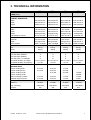
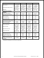
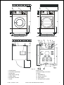
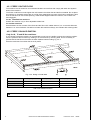
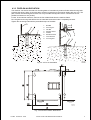
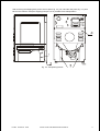
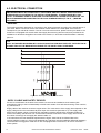
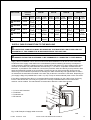
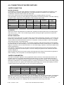
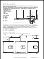
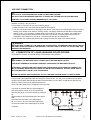
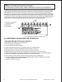
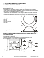
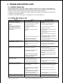
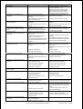
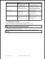
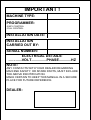
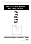
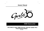
FS 6-16 INSTALLATION AND MAINTENANCE MANUAL PUBLICATION DATE : 05/02 100646 SOFT MOUNTED WASHER EXTRACTOR WITH ELECTRONIC PROGRAMMER 1. TABLE OF CONTENTS Publication date : 05/02 1. TABLE OF CONTENTS ................................................................................................ 1 2. WARNINGS ................................................................................................................... 2 3. TECHNICAL INFORMATION ........................................................................................ 3 4. MACHINE INSTALLATION ........................................................................................... 7 4.1. MACHINE INSPECTION ....................................................................................................................7 4.2. MACHINE STORAGE.........................................................................................................................7 4.3. MACHINE POSITIONING ...................................................................................................................7 4.3.1 FREELY ON THE FLOOR............................................................................................................8 4.3.2 FREELY ON AN ELEVATION. .....................................................................................................8 4.3.3 FIXED ON AN ELEVATION..........................................................................................................9 4.3.4 LEVELING THE MACHINE ........................................................................................................10 4.4. SHIPPING BARS..............................................................................................................................10 4.5. ELECTRICAL CONNECTION...........................................................................................................12 4.6. CONNECTION OF WATER SUPPLIES ............................................................................................15 4.7. CONNECTION OF LIQUID WASHING SOAPS DOSING..................................................................17 4.8. PREPARING THE MACHINE FOR OPERATION..............................................................................18 5. MAINTENANCE AND ADJUSTMENTS...................................................................... 19 5.1. MAINTENANCE ...............................................................................................................................19 5.2. ADJUSTMENTS AND PART´S EXCHANGES ..................................................................................20 6. TROUBLESHOOTING AIDS ....................................................................................... 25 6.1. ERROR HANDLING .........................................................................................................................25 6.2. PROBLEM CHECK LIST ..................................................................................................................25 6.3. DOOR FAILS TO OPEN ...................................................................................................................27 7. LIST OF RECOMMENDED SPARE PARTS ............................................................... 28 8. PUTTING THE MACHINE OUT OF SERVICE ............................................................ 29 100 646 PUB.DATE : 05/02 INSTALLATION AND MAINTENANCE MANUAL 1 2. WARNINGS FAILURE TO COMPLY WITH THE INSTRUCTIONS IN THIS MANUAL MAY LEAD TO INCORRECT USE OF THE WASHER EXTRACTOR, AND MAY RESULT IN BODILY INJURIES OR DEATH AND/OR DAMAGE TO THE LAUNDRY AND/OR THE WASHER EXTRACTOR. ♦ This English version is the original version. ♦ This instruction is not complete without "User manual“, "Installation and Maintenance manual“, "Programming manual“, ”Spare-parts manual” and "Instruction manual for frequency invertor. ♦ Before installing, operating or maintaining the machine, read and follow these instructions carefully and keep them in a handy place for later use. Safety instructions included in manuals for personnel operating the washing machine must be printed and posted on a visible place near the machine in the laundry room. ♦ Follow all basic and valid safety instructions and laws. Do not bypass the instructions stated in the instruction manual and warnings on the labels. The labels must stay on the machine and they must be legible. ♦ Installation and service can be done only by a service organization with proper authorization. Do not let children use, play in, on, or around the machine. ♦ Any changes concerning the installation which are not described in this Installation Manual must be approved by the supplier or manufacturer. Otherwise, the supplier and manufacturer are not responsible for potential injuries to operators or for any damages. Interventions in the machine execution or functions are not allowed, and the manufacturer refuses any responsibility in such cases. ♦ During transportation and storage never use excessive forces on the carton box because components can be damaged protruding the contour line of the machine. ♦ The washer extractor must be installed on level. If not, the machine may become unbalanced during extraction and, although fitted with an unbalance safety, the machine may become seriously damaged what may result in bodily injuries. ♦ Never transport the machine without the transporting braces mounted. ♦ Never put the machine in operation when the transporting braces are not removed. ♦ To prevent the possibility of electrical shock, make sure the washer has been properly grounded in accordance with the installation instructions and ALL local codes. Use copper conductors only. This appliance must be connected to a supply circuit to which no lighting units or general-purpose receptacles are connected. ♦ The machine must be connected to the power, ground, water, ventilation and steam supply according to the Installation manual, in compliance with the local standards done by qualified technicians with proper authorization. The valid standards for connecting to the local power network (TT / TN / IT, ...) must be followed. ♦ All machines types are produced according the EMC-directive (Electro-Magnetic-Compatibility). They can be used in restricted surroundings only (comply minimally with class A requirements). For safety reasons there must be kept the necessary precaution distances with sensitive electrical or electronic device(s). ♦ If you have a machine with frequency inverter do not change the parameters of the inverter. Doing so can cause serious injury, fire, machine damage, etc. ♦ Before removing top or back panel of the machine, switch power off and wait for at least 10 minutes. Before starting inspection of frequency inverter, check for residual voltage across main circuit terminals + and -. This voltage must be below 30 VDC before you can access the inverter for inspection. ♦ The washer extractor is intended to be permanently connected to fixed wiring. ♦ The washer must not be operated when the finger protection rubbers are removed or damaged. ♦ Do not expose the washing extractor to excessive humidity or extreme temperatures. ♦ Keep the top of the machine clean, without the presence of flammable materials. Do not wash or spray the machine with running water. ♦ Do not operate the washer extractor when parts are broken or missing or when covers are open. The machine may not operate until the fixed guards are put correctly in place. ♦ Do not tamper with the washer extractor controls and do not bypass the safety instructions and the warnings. ♦ Do not store flammable materials around the machine. ♦ Define the dangerous areas in the laundry room and obstruct an admission to them during machine's operating. ♦ Carefully read and follow the instructions on the packaging of detergents. Observe all warnings, cautions and labels to avoid personal injury. Store detergents, laundry aids and disinfectants out of reach of children, preferably in a locked cabinet. Do not put articles soiled with explosif solvents and/or dangerous chemical products in the machine for any reason. Do not open door until cylinder remains stopped and water has been drained from cylinder. ♦ Always disconnect the power supply and close all water and steam valves while servicing the washer extractor. ♦ Although the washer may be in the “off” position, there is still electrical power to the switch supply terminals. Do not repair or adjust belt drive when the machine is in operation. Do not repair or replace any part of the washer, or attempt any servicing unless specifically recommended in the maintenance instructions. Original or identical parts must be used for replacement in this washer extractor. After servicing replace and secure all panels in the original way. Take these measures for continued protection against electrical shock, injury, fire and/or property damage. ♦ If steam is leaking, turn off the main steam supply and contact the maintenance worker. ♦ Turn off the main supply like water, steam, electricity at the end of each operating day. ♦ Check the functioning of the door lock mechanism on regular base. ♦ Regularly once a three months check the proper function of ground and emergency button. ♦ If the installed machines operates with coin, token or similar operation, then the owner-installer must provide a remote-located emergency stop device. This device must be placed in such a way that it is easy and safely accessible for the users. The emergency stop device takes care that at least the control circuit of the washer extractors is interrupted. ♦ Under certain conditions, hydrogen gas may be created in the hot water system that has not been used for two or more weeks. Hydrogen gas is explosive. If the hot water system has not been used for such period open all hot water taps and let the water run out for few minutes. This will release any accumulated gas. As this gas is flammable, do not smoke or use open flames during this time. ♦ The instructions and warnings described in this manual do not include all conditions and situations which may occur during the installation, maintain or operate of your machine. They must be generally understood. Caution and care are factors which are not included in the design of this machine and all persons who install, operate or maintain the machine must be qualified and familiar with the operating instructions. ♦ If any problems or failures occur which you do not understand, immediately contact your dealer, serviceman or manufacturer. = Warnings and labels present on the machine 2 INSTALLATION AND MAINTENANCE MANUAL PUB.DATE : 05/02 100646 3. TECHNICAL INFORMATION LOAD CAPACITY OF DRY LINEN (1/10) DIMENSIONS CABINET DIMENSIONS Width Depth Height PACKING DIMENSIONS Width Depth Height Transportation volume DIMENSIONS OF INNER DRUM Diameter Depth Drum Volume WEIGHT Net Gross ELECTRICAL DATA 1AC 220-240V 50/60Hz 3AC 220-240V 50/60Hz 3AC 380-415V + N 50/60Hz Permitted deviation of voltage Permitted deviation of frequency TOTAL INPUT OF THE MACHINE WITH Electric heating 6kW Electric heating 9 kW Electric heating 12 kW Electric heating 18 kW Without heating or steam Nominal output of motor WASHING FUNCTIONS Washing High extracting G-factor 100 646 PUB.DATE : 05/02 60L 75L 95L 165L 6 kg/13,2 lb 7,3 kg/16.1 lb 10 kg/21 lb 16.5 kg/36.4 lb 660 mm/25.98" 680 mm/26.77" 1050mm/41.34" 660 mm/25.98" 680 mm/26.77" 1050mm/41.34" 660 mm/25.98" 780 mm/30.71” 1110mm/43.70” 830 mm/32.6” 960 mm/37.8” 1285 mm/50.5" 750 mm/29.53" 845 mm/33.27" 1215mm/47.83" 3 3 0.77m /27.19ft 750 mm/29.53" 845 mm/33.27" 1215mm/47.83" 3 3 0.77m /27.19 ft 750 mm/29" 945 mm/27.56" 1275mm/40.35" 3 3 0.90m /31.92 ft 913 mm/36” 1123 mm/44.2” 1500 mm/59" 3 3 1.68m /59.3 ft 530 mm/20.86" 270 mm/10,63" 3 60dm /15.85gal 530 mm/20.86" 330 mm/10,6" 3 73dm /19.28gal 530 mm/21" 420 mm/16.5" 3 95dm /25.1gal 650 mm/25.6” 500 mm/19.7” 166dm³/43.8gal 207 kg 223 kg 210 kg 226 kg 250 kg 268 kg 390 kg 415 kg X X X -6% to +10% V ±1% Hz X X X -6% to +10% V ±1% Hz X X X -6% to +10% V ±1% Hz X X X -6% to +10% V ±1% Hz 6.75 kW 9.75 kW 0.75 kW 0.75 kW 6.75 kW 9.75 kW 12.75 kW 0.75 kW 0.75 kW 7.5 kW 10.5 kW 13.5 kW 1.5 kW 1.5 kW 14.2kW 20.2kW 2.2kW 2.2kW 42 RPM 1000 RPM 300 42 RPM 1000 RPM 300 42 RPM 1000 RPM 300 42 RPM 1000 RPM 363 INSTALLATION AND MAINTENANCE MANUAL 3 CONNECTION WATER CONNECTION Water pressure Recommended water pressure Water inlet Maximal water temperature CONNECTION OF WATER DRAINAGE Via drain valve diameter Flow amount with drain valve CONNECTION OF STEAM Steam connection Steam pressure low Steam pressure high ELECTRICAL CONSUMPTION Light soiled fabrics,wash 60°C(1) Without electrical heating With electrical heating WORKING CONDITIONS Ambient temperature Relative humidity Heigth above sea level Storage temperature BOTTOM LOAD Max.static load on floor Max.dynamic load on floor Frequency of dynamic load NOISE Equivalent sound power level Leq (dB(A)) 0.1-0.8 MPa/ 1-8 bar / 14.5-116 PSI 0.25 MPa / 2.5bar/36.3 PSI G3/4" BSP 90°C / 194°F 0.1-0.8 MPa / 1-8 bar / 14.5-116 PSI 0.25 MPa / 2.5bar/36.3 PSI G3/4" BSP 90°C / 194°F 0.1-0.8 MPa / 1-8 bar / 14.5-116 PSI 0.25 MPa / 2.5bar/36.3 PSI G3/4" BSP 90°C / 194°F 0.1-0.8 MPa / 1-8 bar / 14.5-116 PSI 0.25 MPa / 2.5bar/36.3 PSI G3/4" BSP 90°C / 194°F 76 mm/3" 3.5 l/s 76 mm/3" 3.5 l/s 76 mm/3" 3.5 l/s 76 mm/3" 3.5 l/s G1/2” 1-3 bar 3-8 bar G1/2” 1-3 bar 3-8 bar G1/2” 1-3 bar 3-8 bar G1/2” 1-3 bar 3-8 bar 0.2 kWh 1.2 kWh 0.2 kWh 1.3 kW 0.3 kWh 1.7 kW 0.5kWh 3.5kWh +5°C (41°F) to +35°C (95°F) 30% to 90% without condensation up to 1000 m / 3280 ft 0°C (32°F) to +55°C (131°F) +5°C (41°F) to +35°C (95°F) 30% to 90% without condensation up to 1000 m / 3280 ft 0°C (32°F) to +55°C (131°F) +5°C (41°F) to +35°C (95°F) 30% to 90% without condensation up to 1000 m / 3280 ft 0°C (32°F) to +55°C (131°F) +5°C (41°F) to +35°C (95°F) 30% to 90% without condensation up to 1000 m / 3280 ft 0°C (32°F) to +55°C (131°F) 2413 N 650 N 16 Hz 2492 N 730 N 16 Hz 3002 N 1100 N 16 Hz 5450N 1220 N 16Hz < 70 dB(A) < 70 dB(A) < 70 dB(A) < 70 dB(A) (1) Depends of temperature of cold and hot water supply 4 INSTALLATION AND MAINTENANCE MANUAL PUB.DATE : 05/02 100646 60/75/95 L machines 165 L machine with frequency control drive Fig. 3.1. 1. Control panel 2. Connection liquid soap 3. Serial plate 4. Soap hopper venting 5. Water supply 6. Frequency convertor 7. Fuses 100 646 PUB.DATE : 05/02 8. Main switch 9. Electrical supply connection 10. Drain 11. Adjustable leg 12. Steam connection 13. Soap hopper 14. Emergency/Coin system INSTALLATION AND MAINTENANCE MANUAL 5 6 CAPACITY 60L CAPACITY 75L CAPACITY 95L CAPACITY 165L A 660 mm / 25.98” 660 mm / 25.98” 660 mm / 25.98” 830 mm / 32.68” B 685 mm / 26.97” 685 mm / 26.97” 785 mm / 30.91” 960 mm / 37.8” C 1070 mm / 42.13” 1070 mm / 42.13” 1130 mm / 44.49” 1285 mm / 50.54" D 560 mm / 22.05” 560 mm / 22.05” 560 mm / 22.05” 715 mm / 28.15” E 585 mm / 23.03” 585 mm / 23.03” 685 mm / 26.97” 815 mm / 32.09” F 20 mm / 0.79” 20 mm / 0.79” 20 mm / 0.79” 0 mm / 0” G 420 mm / 15.54” 420 mm / 15.54” 480 mm / 18.90” 430 mm / 16.92" H 263 mm / 10.35” 263 mm / 10.35” 263 mm / 10.35” 300 mm / 11.81” I 910 mm / 35.83” 910 mm / 35.83” 970 mm / 38.19” 1135 mm / 44.68" J 103 mm / 4.06” 103 mm / 4.06” 103 mm / 4.06” 120 mm / 4.72” K 980 mm / 38.58” 980 mm / 38.58” 1040 mm / 40.94” 1195 mm / 47" L 44 mm / 1.73” 44 mm / 1.73” 44 mm / 1.73” 44 mm / 1.73” M 835 mm / 32.87” 835 mm / 32.87” 895 mm / 35.24” 1015 mm / 39.95" N 78 mm / 3.07” 78 mm / 3.07” 78 mm / 3.07” 55 mm / 2.36” O 375 mm / 14.76” 375 mm / 14.76” 375 mm / 14.76” 415 mm / 16.34” P 10 mm / 0.39” 10 mm / 0.39” 10 mm / 0.39” 15 mm / 0.6” Q 445 mm / 17.52” 445 mm / 17.52” 445 mm / 17.52” 530 mm 20.86" R 700 mm / 27.56” 700 mm / 27.56” 700 mm / 27.56” 700 mm / 27.55” S 600 mm / 23.6” 600 mm / 23.6” 600 mm / 23.6” 600 mm / 23.6” INSTALLATION AND MAINTENANCE MANUAL PUB.DATE : 05/02 100646 4. MACHINE INSTALLATION 4.1. MACHINE INSPECTION When the machine is delivered, it is necessary to do a visual inspection for any damage that may have occurred during transit. If the package or pallet are damaged or signs of possible damage are evident, let the carrier note the condition on the shipping papers before the shipping receipt is signed. Remove the package as soon as possible and check if the information on the serial plate correspond with your order. The serial plate is located on the rear of the machine, fig. 4.1. This determines the type of model you have bought, the voltage and the serial number. Fig. 4.1.Serial plate Check if the machine is not damaged and if all the accessories are included according to your order. The accessories and manuals are located inside the machine. 4.2. MACHINE STORAGE When the machine will be stored after delivery, be sure this is followed: - Use the delivered package to protect the machine against moisture and dirt. - The storage temperature is between 0°C and 55°C. - The machine may not be installed within the reach of spraying water. - Avoid severe climatic storage conditions and excessive humidity. When the temperature changes and this causes damp, you must avoid water under and around the machine and also on his covers. - If possible, leave the machine in the transporting package or at least let it set on the transporting wooden id until the time of final installation on the foundation according the chapter 4.3. of this manual. 4.3. MACHINE POSITIONING ! WARNING ! IF THE MACHINE IS LOCATED ON AN ELEVATED BASE FOR EASIER OPERATION, THE FRONT LEGS OF THE MACHINE SHOULD BE SERCURED FOR SAFETY REASONS. - Before placing the machine on its place, remove the packaging, loosen the rear panel (see fig. 4.4. pos 4) and the service panel (see fig. 4.4. pos 5). Remove the four bolts, which holds the machine on the wooden pallet. Lift up the machine carefully, take care not to damage the machine components. - Leave at least a 0.6 m / 23,6“ free space between the rear panel of machine and the wall. Leave at least a 0.01 m / 0.39" free space between the side panel of the machine and the wall or other machine. Above the machine must be minimum 0.7 m / 27.56” of free space for the maintenance access. - All passages and spaces the machine has to be transported through at installation should be reasonably dimensioned to meet the height and width of the machine including the package. - Never push, pull or press the components protruding from the contour line of machine(control panel, door, control elements, water inlet and outlet pipes, etc.). - Make sure that the filling door is closed during handling. - Take care that the floor where the machines will be placed is underneath supported. The washer should not be installed on an upper floor or over a basement without approval of structural engineer about the requirements of permissible loading, vibrations and noise level in the building. - Take care that the floor where the machines will be placed is not combustible. 100 646 PUB.DATE : 05/02 INSTALLATION AND MAINTENANCE MANUAL 7 4.3.1 FREELY ON THE FLOOR The machine is to be located on a not elevated leveled concrete floor that comply with static and dynamic stress of the machine. The friction coefficient must be higher then 0,5 between the rubber feet and the floor material. Do not place the machine on a smooth surface but on a rough floor material like concrete. If the friction coefficient is less, then the machine can move while spinning. If this should happens fasten the machine, see “Fasten with achoring bolts”. For 60, 75and 95 liter machines Position the machine only on his 4 adjustable rubber feet. For 165 liter machines Place between the four corners of the frame and the floor a thin rubber sheet of 10 x 10 cm with thickness between 1 en 2 mm maximum. We advice to fasten this machines always, see “Fasten with achoring bolts”. 4.3.2 FREELY ON AN ELEVATION. Only for 60, 75 and 95 liter machines. If you choose to place the machine on a metal base or pad, use a U-profile to secure the machine position. Fix the U-profile to the iron frame by welding or fix it to the floor by ancoring bolts. This is necessary to prevent that the machine moves from the base. Make a base according, fig. 4.3.2. Place the machines front rubber feet in the U-profile. Fig. 4.3.2. Design of metal base Distance A Distance B Distance C Capacity 60L 660 480 590 Capacity 75L 660 480 590 Capacity 95L 760 480 590 Tab 4.3.2. Distances Frame ! 8 WARNING ! NEVER DO THIS FOR A 165 LITER MACHINE INSTALLATION AND MAINTENANCE MANUAL PUB.DATE : 05/02 100646 4.3.3 FIXED ON AN ELEVATION The machine can also be secured to a mounting base or foundation by means of bolts and anchoring bolts to assure the safety. When a concrete pad or a frame is used then is the maxium height 305 mm (12”). The pad or frame must be designed so that it can carry the static and dynamic forces. The tickness of iron profiles is minimuim 4 mm (0.158”). For 60, 75 and 95 liter machines, remove the four rubber feeds from the machine frame. Do not tighten anchoring bolts before the concrete base around the bolts is completely secured. Tighten the anchoring bolts with the prescribed torque of the bolts. 1. 2. 3. 4. 5. 6. 7. 8. Bolt M8 Securing nut Nut M8 Machine frame Washer Elevation frame Concrete floor Ancoring bolt Fig. 4.3.3.A On an elevatation Fig. 4.3.3.B Frame fixation dimensions 100 646 PUB.DATE : 05/02 INSTALLATION AND MAINTENANCE MANUAL 9 Capacity 60L Capacity 75L Capacity 95L Capacity 165L X1 660 mm / 25.98” 660 mm / 25.98” 660 mm / 25.98” 830 mm / 32.7” X2 560 mm / 22.05” 560 mm / 22.05” 560 mm / 22.05” 715 mm / 28.1” X3 50 mm / 1.97” 50 mm / 1.97” 50 mm / 1.97” 57.5 mm / 2.3” X4 685 mm / 26.97” 685 mm / 26.97” 785 mm / 30.91” 960 mm / 37.8” X5 455 mm / 17.91” 455 mm / 17.91” 565 mm / 22.24” 815 mm / 32.09” X6 130 mm / 5.12” 130 mm / 5.12” 130 mm / 5.12” 80 mm / 3.15” X7 110 mm / 4.33” 110 mm / 4.33” 110 mm / 4.33” 130 mm / 5.2” Tab 4.3.3. Distances anchoring bolts 4.3.4 LEVELING THE MACHINE ! WARNING ! THE MACHINE MUST RELIABLY REST IN ALL FOUR CORNERS OF THE MACHINE! THE MACHINE MAY NOT ROCK. THE MACHINE MUST BE IN WATER LEVELLED POSITION. For 60, 75 and 95 liter machines The rubber feets are screwed on the bottom of the machine frame and are adjustable with a wrench size 13 and 17 mm. Check the position of the top of the machine by a water level and adjust machine legs, fig.3.1, pos.11. Adjust the four rubber feet until the machine is leveled and tighten the nuts M10 back to the bottom of the frame. For 165 liter machines The 165 liter machines don’t have rubber feets for adjustment to water level. When it is necessary use thin hard plates of 10 x 10 cm with thickness of 1 mm and place them under the frame corner of the lowest position. Use more of them until the machines stands water level. It is always adviseable to bolt down this machine after leveling. Take care that the machine is in the lowest possible position. If the machine with his cabinet rocks can it damage the machine cabinet. The manufacturer is not responsible for consequences caused by a wrong installation. 4.4. SHIPPING BARS ! WARNING ! DO NOT TRY TO OPERATE THE MACHINE WITHOUT REMOVING THE SHIPPING BARS DO NOT TRANSPORT THE MACHINE WITHOUT SHIPPING BARS MOUNTED. OTHERWISE THIS CAN LEAD TO INJURY TO PEOPLE AND CAN DAMAGE THE MACHINE. The machine is blocked for transport. This eliminates all possible movement of the tub during transportation. There are 3 striking shipping bars which must be removed before putting the machine into operation. 1. Remove fixation plate front, fig. 4.4. pos 1. 2. Remove fixation plate rear right, fig. 4.4. pos 2. 3. Remove fixation plate rear left, fig. 4.4. pos 2. IMPORTANT : UNSCREW ONLY THE NUTS WHERE INDICATED ! 10 INSTALLATION AND MAINTENANCE MANUAL PUB.DATE : 05/02 100646 After removing the shipping bars put the service panel, fig. 4.4. pos 3 and the rear panel, fig. 4.4. pos 4 back on the machine. Keep the shipping bars pos 1,2 for possible future transportation. Fig. 4.4. Transporting braces 100 646 PUB.DATE : 05/02 INSTALLATION AND MAINTENANCE MANUAL 11 4.5. ELECTRICAL CONNECTION WARNING ! ! THE MACHINE MUST BE CONNECTED TO THE POWER, GROUND, WATER, VENTILATION AND STEAM SUPPLY ACCORDING TO THE INSTALLATION MANUAL, IN COMPLIANCE WITH THE LOCAL STANDARDS DONE BY QUALIFIED TECHNICIANS WITH PROPER AUTHORIZATION. THE VALID STANDARDS FOR CONNECTING TO THE LOCAL POWER NETWORK (TT / TN / IT, ...) MUST BE FOLLOWED. GENERAL The machine has been designed for connecting to the electrical network according to the specifications of your order. Before connection check if the electrical values stated on the serial plate of the machine correspond to your electrical network. If not do not connect the machine, please contact your dealer. If the machine is not equipped with a main switch then supply disconnecting devices need to be provided in the installation for all electrical supplies connected to the machine, in accordance with EN 60204-1 standard, point 5.3. ! WARNING ! ONLY AUTHORIZED WORKERS WITH A VALID QUALIFICATION MUST EXECUTE THE ELECTRICAL CONNECTION OF THE MACHINE ACCORDING TO THE VALID LOCAL STANDARDS. Fig. 4.5.A. Example of electrical connection SUPPLY CABLE AND SAFETY DEVICES If there is no mainswitch at the back of the machine, there must be installed a circuit breaker (with properties according to the local standards) to isolate each washer for a safe disconnecting of the machine, e.g. maintenance. Supply cable of the machine must have copper wires. The cross section of the supply wires depends on the supply voltage and on the total electrical power input of the machine (see table 4.3). The supply cable safety device against a short-circuit fault and overloading must be performed by automatic breakers or fuses in the laundry switchboard. The recommended minimal cross-section of the supply wires as well as the values of fuses (F) for the supply are stated in table 4.5. In all cases were the local standards requirments are higher, these has to be followed above the recommendation in table 4.5. If the local standards say that there must be installed a differential (leakage) current breaker we suggest to install one of 100 mA eqiupped with invertor drive, 30 mA for convential motor system. 12 INSTALLATION AND MAINTENANCE MANUAL PUB.DATE : 05/02 100646 ELECTRIC HEATING: Without electrical heating EXECUTION: 6000 W 9000 W 12000 W 18000 W Fuse breaker cross Fuse cross Fuse cross Fuse cross Fuse cross section breaker section breaker section breaker section breaker section 1AC 220-240V +PE 2xD16 2+1 2.5mm² / / / / / / / / 3AC 200-240V +PE 3xD16 3+1 2.5mm² / / / / / / / / 3AC 380-415V +N+PE 4xD16 4 + 1 4 x C16 4 + 1 4 x C20 4 + 1 4 x C25 2.5mm² 2.5mm² 2.5mm² 4+1 4mm² 4 x C40 4+1 6mm² 3AC 220-240V +PE 3xD16 3 + 1 3 x C25 2.5mm² 3 x C40 3+1 6mm² 3 x C60 3+1 10 mm² 3AC 440V +PE 3xD16 3 + 1 3 x C16 3 + 1 3 x C20 3 + 1 3 x C25 2.5mm² 2.5mm² 2.5mm² 3+1 4mm² 3 x C32 3+1 4mm² 3+1 4 mm² 3 x C32 3+1 4mm² Tab 4.5. The values of securing and minimal wire section recommended by the manufacturer SUPPLY CABLE CONNECTION TO THE MAC H INE ! WARNING ! THE PROTECTIVE CONDUCTOR MUST BE LONGER SO THAT WHEN THE CABLE IS PULLED OUT ACCIDENTALLY, THIS CONDUCTOR IS DISCONNECTED AS THE LAST ONE! ! WARNING ! THE WASHER EXTRACTOR IS INTENDED TO BE PERMANENTLY CONNECTED TO FIXED WIRING. Push the cable through the turnbuckle and connect the wires with the main switch. The diameter of the supply cable must between 10-14 mm for PG16 turnbuckle and between 13-18 mm for PG21 turnbuckle. Conductors of the supply cords shall not be consolidated by lead-tin soldering where they are subject to contact pressure, unless the clamping means is constructed so that there is no risk of a bad contact due to cold flow of the solder.The phase terminals are marked by L1, L2 and L3. A separate insulated terminal, labeled N, is provided for the neutral wire. Connect the protection earth wire directly to the protection earth terminal (marked PE) located on the rear bridge. Tighten the cap nut of the turnbuckle. By this way the rubber ring in the turnbuckle is pressed, thus securing the cable mechanically and against water. If there’s no mainswitch the terminals are marked in the same way so also the connection is the same. Depending on your supply voltage it is possible that L2 and L3 (1 AC) or N (3 AC without Neutral) must not be connected. If the cable is attached from above, it is recommended to make a sagging on the cable in front of its entry into the cable turnbuckle. In this way an ingress of the running condensed water into the bush and/or machine can be avoided. The manufacturer recommends to attach the cable from beneath. 1. L1,L2,L3 and N terminal 2. Turnbuckle 3. Turnbuckle nut 4. PE terminal Fig. 4.5.B. Example of supply cable connection 100 646 PUB.DATE : 05/02 INSTALLATION AND MAINTENANCE MANUAL 13 CHECKING ROTATION DIRECTION CHECK IF THE DRUM ROTATES FROM THE FRONT VIEW IN CLOCKWISE DIRECTION DURING EXTRACTION. IF IT ROTATES IN OPPOSITE DIRECTION, DISCONNECT TWO PHASES OF THE CONNECTION FROM THE FREQUENCY CONVERTOR TO THE MOTOR , SWITCH THEM OVER AND CHECK AGAIN THE ROTATION DIRECTION. Fig. 4.5.C. Spin direction MULTIPLE MACHINES IN LINE SIMPLE PHA SE When multiple single phase machines are connected to the same electrical network, it is necessary to connect the machines according to fig. 4.9. The phase of the frequency control and motor which is connected to the terminal inside the machine, has to be connected alternatively for the first machine with the first phase L1 of the network, the second machine with the second phase L2, … The fourth machine must again be connected to the first phase L1. This assures a better load of the electrical network. Fig. 4.5.D. Multiple machines in line 14 INSTALLATION AND MAINTENANCE MANUAL PUB.DATE : 05/02 100646 4.6. CONNECTION OF WATER SUPPLIES WATER CONNECTION WATER HARDNESS It is advisable to contact the water supplier for information concerning the properties of the water in your area. Good wash results are dependent also on the water hardness. For medium to very hard water, consideration should be made to make the water softer. Only in some cases is the use of hard water desirable, such as adding softener in the linen. The soap supplier can help you with making the right decisions concerning hard water, soft water, washing programs, type of soap and other related items to have the best wash results. dH fH gr/gal Characteristics mmol / dm3 England Germany France USA soft 0 - 1,25 0 - 7° 0 - 12° 0 - 8,75° 0-3 medium 1,25 - 2,5 7 - 14° 12 - 25° 8,75 - 17,5° 3-7 hard very hard 2,5 - 3,75 above 3,75 14 - 21° above 21° 25 - 37° above 37° 17,5 - 26,3° above 26,3° 7 - 15 above 15 Tab.4.6.A. HOT WATER When the machine is provided with a hot water inlet, we advise connecting this inlet to a hot water supply that is set to 70°C – 158°F. The hot water supply needs to be large enough to provide the required hot water for the washers. WATER CONNECTION Most machines are made with 2 or 3 water inlets. One is always marked with „soft water“. If more inlets are present, they are marked with „Hot water“ or „Hard water“. For connection dimensions see fig. 3.1. Always use the flexible hose delivered with the machine, if not present, contact your dealer. In each case do not use a fixed connection to the water supply. For the proper function of the machine, it is necessary to keep the water pressure within the limits stated in the technical data. It is also necessary to connect all available water inlets to a water supply. If a hard water supply is not present, connect it with soft water. If no hot water supply is present, contact your dealer for the proper required action. The machine is equipped with 3/4" inlet valves. First let the water flow from the tap into the drain before connecting the machine to the water system. This is for cleaning the pipes from dirt. Otherwise the filters could be stopped up. Open the taps and check the connection points at the taps and at the inlets of the machine for tightness. If water is leaking, correct the position of the seal and tighten the screw coupling. WATER CONSUMPTION The water consumption depends on the programmed values in the timer. These values are shown in the program manual. For a prewash and wash the low water level (LL) is used. The high water level (HL) is used for rinsing. The programmed units correspond to an average amount of water. You can calculate the total water consumption in one washing program by counting up the amount of water by each washing step. An example is shown for a system with cold and warm water supply for a machine with capacity of 95 liter. A system without warm water supply you can count with the total amounts. Program 60°C Light soiled linen Consumption (liter) 1. Wash 60°C 2. Rinse (3x) TOTAL Cold water 15 Warm water 16 Total 31 46 61 0 16 138 169 Tab 4.6.B. Water consumption The values received from this calculation is only an estimation of the real water consumption. The deviation depends on many circumstances. In the wash cycle for example there will be taken a mix of warm water and cold water. The mix of the water depends on the temperature of both. The total amount of water consumed depends also on the loading of the drum with linen and the turning of the drum. 100 646 PUB.DATE : 05/02 INSTALLATION AND MAINTENANCE MANUAL 15 WATER DRAIN CONNECTION The machine is equipped with a drain valve of 75 mm (3”) diameter. The drain is situated on the rear of the machine. The drain has to be connected to the waste channel. You can use the elbow, which is a part of the delivery. Secure the elbow with a clamp. THE WASTE CHANNEL MUST BE LOCATED LOWER THAN THE DRAIN PIPES BECAUSE THE WATER DISCHARGES FROM THE MACHINES BY GRAVITY. DO NOT REDUCE THE DIAMETER OF THE MACHINE DRAIN PIPES. 1.waste channel cover 2.drain elbow ∅75mm(3”) 3.clamp 4.waste channel Without rubber feet : X1 = 55 mm With rubber feet : X1 = 73 mm X2 > 100 mm X3 > 20mm Fig. 4.6.A. Design of the waste channel The main drainpipe must have the capacity to be able to handle the total output of all connected machines. There must also be a hole every twenty meter in the drainpipe, fig. 4.6.B, pos 1 to assure the good working of the drain. This allows air in the main drain and facilitates drainage of the water flow. Every time a machine is coupled on the drainpipe, the diameter of the tube or the width of the waste channel must be more. See, fig. 4.6.B, D1,D2,D3. The recommended drain pipes diameter are: D1 = 75 mm / 3” for one machine D2 = 100 mm / 4” for two machines D3 = 125 mm / 5” for three machines If the main drain cannot be sufficiently deodorized, install a deodorizer per machine. Fig. 4.6.B. Recommended drain pipe diameters 16 INSTALLATION AND MAINTENANCE MANUAL PUB.DATE : 05/02 100646 AIR VENT CONNECTION ! WARNING! WATCH OUT FOR STEAM ESCAPE FROM THE MACHINE VENTING ! DO NOT COVER THE MACHINE VENTING; IT SERVES AS A STEAM OUTLET AND MACHINE VENTING. IT ALLOWS A PROPER MEASURING OF THE LEVEL.. On the backside, the machine is provided with a drum air vent terminal (see fig. 3.1 pos 4) of external diameter 75 mm (3"). Do not cover it! For the safety of everyone do one of the following things : 1. Make sure that no-one can reach the backside of the machine. 2. You can connect the machine-venting pipe to the laundry central duct for exhausting the steam out of the building or to another room where it is safe to emit it. The piping material must withstand a temperature of80°C / 176°F. You can attach a rubber elbow on the machine by using of a clamp. The central duct formultiple venting must be dimensioned for the total cross section of venting pipes of all machines. Acalibration of the machine’s “zero level “ must be made after the duct attachment. 3. You can also use a rubber pipe (elbow and a clamp) and emit the vapor in the waste channel. WARNING! BE SURE THAT THE END OF THE PIPE IS NOT IN THE WATER, OTHERWISE THERE WOULD BE AN ACCUMULATION OF STEAM IN THE MACHINE. THIS CAN LEAD TO INJURY TO PEOPLE AND CAN DAMAGE THE MACHINE!! ! 4.7. CONNECTION OF LIQUID WASHING SOAPS DOSING It is possible to connect an external dosing of liquid soaps to the machine. ! WARNING ! DISCONNECT THE MACHINE SUPPLY POWER INLET BEFORE INSTALLATION. THE INLET TERMINALS ARE UNDER CURRENT EVEN WHEN THE MAIN SWITCH IS OFF ELECTRICAL CONNECTION AND CONNECTING THE MACHINE INLETS MUST BE CARRIED OUT BY AUTHORIZED WORKERS ACCORDING TO INSTALLATION MANUAL INSTRUCTIONS AND IN ACCORDANCE WITH VALID LOCAL STANDARDS. AFTER THE HOSES ARE CONNECTED PUT ALL MACHINE COVERS BACK TO THEIR PLACES. For connecting the liquid soap inlets and wiring for machines 60l / 75l / 95l you must take of the top panel. Unscrew the two bolts and take the top panel of the machine. For the 165l it is sufficient to open the top panel by means of the two keyswitches at the front. At the right side panel there is a support for the top panel. The hoses of external dosing of liquid soaps are pushed through the holes in the rear panel after removing the plugs. The hoses should be protected by rubber bushings where penetrating the rear panel. After this make as many holes in the soap hopper, fig. 4.7.A, pos 1) as you have liquid soap hoses. Connect the hoses to the soap hopper by means of clamps. Fig. 4.7.A. Connection soap hopper 100 646 PUB.DATE : 05/02 INSTALLATION AND MAINTENANCE MANUAL 17 WARNING ! CHECK IF THE HOSES ARE TIGHTEN BY THE CLAMPS ! ANY LEAKAGE OF CHEMICALS MAY CAUSE CORROSION ON THE PARTS IN THE MACHINE. ! The liquid soap pump system supply needs to be connected to an external electrical source. Only authorised workers with a valid qualification must execute the electrical connection of the machine according to the valid local standards. Do not connect the pump system in the machine. The liquid soap signals are available in the machine on a connector, see fig. 4.7.B. The first terminal is the common line of the signals. The following terminals are the signals that will be active depending of the programmed wash programme. These signals have a potential of max. 250V. Use a cable that is sufficcient for their function and pass it in the appropriate opening in the machine. Connect these signal terminals like the manufacturer of the liquid soap system requires. The liquid soap system may draw maximum 0,1A out the control circuit of the washer-extractor. 1. terminals for connection liquid soap pumps 2. Neutral line 3. Soap signals Fig. 4.7.B. Electrical connection soap pumps 4.8. PREPARING THE MACHINE FOR OPERATION CHECKING BEFORE PUTTING INTO SERVIC E 1. Make sure the transporting braces are removed. 2. Put out all things from wash drum. 3. Check the machine horizontal position. 4. Check connection and clearance of your drain, channel or central drainage. 5. Check protective connection (earthing) and electrical supply connection. 6. Open water valves to machine and check hose and connections for leaks. 7. Read carefully the „User manual“ and „Programming manual“, which are a part of delivery. 8. Initialize the programmer after machine installation. The calibration of the zero level must not happen anymore. This calibration is executed in the factory and is not changeable. 9. Check the drum rotation direction during extracting according to the extracting label. 10. Check the vibration switch function during extracting (see also chapter 5.2 adjustments and parts exchange, adjustment of the vibration switch. 11. Check the emergency function 18 INSTALLATION AND MAINTENANCE MANUAL PUB.DATE : 05/02 100646 5. MAINTENANCE AND ADJUSTMENTS ! WARNING ! ALWAYS FOLLOW SAFETY INSTRUCTIONS! DO NOT BYPASS ANY SAFETY DEVICES OR THEIR PARTS, ANY INTERFERENCE TO THE MACHINE FUNCTIONS AND CONSTRUCTION ARE PROHIBITED. BEFORE MAINTENANCE WORK DISCONNECT THE MACHINE POWER SUPPLY. In case of serious failures call the technical service of your supplier. When replacing any parts of the machine, exchange them with original parts obtained from your dealer or ordered through the spare parts catalogue. 5.1. MAINTENANCE CHECKING AND MAINTENANCE DAILY 1. Remove the linen or other parts (paperclips, needles, …) who are left lying in the drum to avoid injuries and damage to the rubber door seal, seals, glass etc. 2. Clean the door seal from any remaining detergent and other foreign matter. 3. Clean the top and body when water or detergent traces are on the machine. Use a damped cloth, do not use abrasive cleaners. Dry with a soft cloth. 4. Hoppers must be cleaned at the end of each working day. Remove sediments inside the reservoir by means of a plastic spatula and splash by water. 5. Check water and possible steam inlets for leakage. 6. At the end of the working day, open the machine door to allow airing out the machine and to prolong the door gasket life service. We recommend to shut off all electrical power inlets and main water inlets. CHECKING AND MAINTENANCE EVERY THREE MONTHS ! WARNING ! HOT MACHINE PARTS SHOULD BE ALLOWED TO COOL FIRST ! 1. Check if the drain valve is not leaking during the wash process.It is also important that the valve opens properly afterwards (drain valve opens when electrical power falls out).Wash out the drain if the water doesn’t drain fluent. 2. Check for the belt tightness or possible damage; therefore remove the machine rear cover. 3. Check the tightness of the bolts according to chapter 5.2. 4. Check visually all hoses and connection inside the machine for leaking. 5. Make sure that the control components are protected against moisture and dust during the clean up.Wipe and clean up the machine inside. 6. Tighten the contacts of heating elements terminals on machines with electrical heating. CHECKING AND MAINTENANCE EVERY SIX MONTHS 1. The filters in the water connection at the valves need to be cleaned. Turn off the tap. Unscrew the hoses at the back of the appliance. Take out the filter at the center with pointed pliers, clean and re-insert. When re-attaching the hoses, make sure that the seals are seated correctly. Check water inlets for leaks. Tighten the connections or replace the seals of the inlet hose if necessary. ! BEFORE REMOVING TOP OR BACK PANEL OF THE MACHINE, SWITCH POWER OFF AND WAIT FOR AT LEAST 10 MINUTES. BEFORE STARTING INSPECTION OF FREQUENCY INVERTER, CHECK FOR RESIDUAL VOLTAGE ACROSS MAIN CIRCUIT TERMINALS + AND -. THIS VOLTAGE MUST BE BELOW 30VDC BEFORE YOU CAN ACCESS THE INVERTER FOR INSPECTION. 2. Clean and remove dirt and dust from: – the cooling fin of the inverter – the motor cooling fins – the internal ventilator of the inverter (if present) – the external ventilator (if present) – the external air relieves of the machine – check if ventilator in coolfins of inverter (if present) is functional – check if external ventilator (if present) is functional 100 646 PUB.DATE : 05/02 INSTALLATION AND MAINTENANCE MANUAL 19 5.2. ADJUSTMENTS AND PART´S EXCHANGES ADJUSTMENT OF DOOR SEAL THRUST For 60, 75, 95 liter machines If there is a water leakage around the door it is necessary to find out if the problem has been caused due to the door shift out of its position or if the door seal thrust should be adjusted. In some cases the door seal has to be replaced.(Fig. 5.2.A). 1. For increasing (resp. decreasing) the pressure of the door seal, take off spacers (pos 1) (resp. add spacers) between the door frame and the hinge blocks. Therefore remove the screws (pos 4) on the door frame.Tighten the screws again after positioning the spacers. 2. The adjustments of the door seal pressure must be executed as follows. The door rubber (pos 2) must still touch the tub rubber at the hinge side when the door opens at 5°. 3. Adjust the position of the door by loosening the screws (pos 4) on the door frame. The door hook must be right in the center of the door lock opening. Tighten the screws (pos 4) again after correct positioning of the door. 1. Adjusting spacers of the door hinge 2. Door seal 3. Door glass 4. Bolts of the door hinge 5. Door frame Fig. 5.2.A. Door fastening For 165 liter machines 1.Loosen two bolts (6) fastening the top door hinge (7), fig. 5.2.B. BE CAREFUL TO AVOID POSSIBLE FALLING OF THE DOOR WITH LOOSENED HINGE TO THE FLOOR. RISK OF INJURIES! 2.Take off the elimination washer (8). 3.Tighten the two bolts (6) fastening the top door hinge. 4.Do the same with the bottom hinge. 5.Check if the door hinge has not moved, closing and opening of the door must be smooth. If the thrust adjusting has not been sufficient, exchange the door seal. 6. Hinge bolt 7. Hinge 20 Fig. 5.2.B. Door fastening 8. Elimination washer 9. Door INSTALLATION AND MAINTENANCE MANUAL PUB.DATE : 05/02 100646 REPLACEMENT OF DOOR RUBBER For 60, 75, 95 liter machines 1. Open the door. Remove the door glass (Fig. 5.2.A, pos.3) with rubber (pos 2) from the stainless steel door (pos 5) by pushing it towards the drum. Do it carefully, do not damage the glass. 2. Remove the seal (pos 4) from the glass. 3. Place a new rubber seal with wider groove on the glass with the edge up. 4. Moisten the seal groove (pos 2) for door with soap water. Place a smooth cord in the groove all around. Tighten up the margin by cord and fit the unit to the door opening (pos 5) (with the clip up). Hold one end of the cord firmly on the door. Pull the other cord end towards the center of the glass for the rubber edge properly fit in. ADJUSTING OF VIBRATION SWITCH ! WARNING! MAKE SURE THE MACHINE IS DISCONNECTED FROM POWER SUPPLY BY PULLING OUT THE PLUG! The vibration switch is an important safety element which must – if correctly adjusted – stop the machine if excessive vibrations and shaking occur due to an unbalance caused by improper distribution of linen in the washing drum. It is recommended that at the first installation and then once in a year a qualified worker verifies the vibration switch, fig. 5.2.C. 1. Dismantle (60l / 75l / 95l) the top cover by two bolts on machine rear for machines. For the 165l the top cover can be folded open and supported by the support at the right side panel. 2. Check the distance between microswitch (pos 1) and the limiter (pos 2). 3. The distance between the microswitch and the spring holder must be 0.2 mm. 4. Check the position and condition of the sensor (pos.3) in the limiter (pos 2). It must be exactly in the center of the hole! Unscrew the tiltswitch plate and move the plate up, down, left and right to adjust the center of the sensor to the center of the hole on the limiter. 5. At the first installation and then once in a year the vibration switch has to be tested on his functionality. After starting the extraction mode and after reaching the maximum RPM, carefully switch over the vibration switch by moving the flexible sensor manually. The machine will stop extracting and will return to 0 RPM. WARNING! DO NOT OPERATE THE MACHINE IF THIS FUNCTION DOESN’T WORK ANYMORE! DO THIS CAREFULLY TO AVOID INJURIES BY VIBRATING AND FIRM PARTS OF THE MACHINE! AFTER YOU HAVE CHECKED THE FUNCTION, MOUNT THE MACHINE COVER BACK! ! 100 646 PUB.DATE : 05/02 INSTALLATION AND MAINTENANCE MANUAL 21 1. Microswitch 2. Limiter 3. Sensor Fig. 5.2.C. Vibration switch REPLACEMENT / REGULATION OF THE BEL T ! WARNING! MAKE SURE THE MACHINE IS DISCONNECTED FROM POWER SUPPLY BY PULLING OUT THE PLUG FROM THE SOCKET. On a new machine and after a belt replacement, make an inspection of the belt tightness : 1. After first 24 hrs of operation 2. After first 80 hrs of operation 3. Every 6 months or every 1000 operation hours – which ever come first. The belts are accessible from the rear of the machine. If the belts are too tight the bearing seating are under stress and their life service will be shortened. If the belts are too loose they can be slipping on the pulley and can cause a noisy operation. In the case when it’s needed, tighten the belts. FOR 165 LITER MACHINES The testing force of belt tensioning is 200 N which can be measured by tension meter. Procedure for approximate belt tensioning with belt deflection 20 mm for machine 165L: apply a load of 5,5 kg to the middle of the belt. Change the belts if they are worn out or damaged. ! TO CHANGE THE BELTS: NEVER USE A CROWBAR TO TAKE OFF THE BELTS OVER THE PULLEY GROOVES! 1. Dismantle the rear panel, fig. 5.2.D, (pos 1). 2. Take off the belts, (pos 2.) by pulling the belt and turning the drum pulley (pos 5). 3. Put a new belt (2) of identical type on pulleys (pos 5 and 8). The re-assembly of the belts is done in the reverse order as the disassembly. 4. The belt must be placed in the correct motor pulley trenches in such way the belt is running in the center of the drum pulley. To tighten or loosen the belt tension : 1. Loosen the bolts (pos 4) for securing the motor position. 2. First unscrew the lower nut (pos 6) and then unscrew the upper nut(pos 7) for increasing the belt tension. 3. For decreasing the belt tension screw the lower and upper nut (pos 6 and 7) and lift the motor suspension. After this tighten all the bolts. 22 INSTALLATION AND MAINTENANCE MANUAL PUB.DATE : 05/02 100646 4. After the belt replacement, check the pulley alignment, the tightness of belts, bolts and nuts. Keep the belts and pulleys clean and free of oil, lubricants, water etc. 1. Rear panel 2. 2 x Belt 3. 2 x Screw M12 : Alignment 4. 2 x Screw M10 5. Motor pulley 6. Securing nut of bolt M16 (lower) 7. Securing nut of bolt M16 (upper) 8. Drum pulley Fig. 5.2.D. Regulation of belt WATER FILTERS Machines are equipped with filters on water inlets. It is necessary to clean up the filters occasionally to avoid a prolongation of filling the machine with water. Intervals of cleaning depend on the quality of the water , for example foreign particles in the water line. WARNING ! ! BEFORE YOU START THE FILTER CLEANING CHECK IF THE INLET OF HOT WATER TO THE MACHINE IS CLOSED AND COLD. TIGHTENING MOMENTS ! WARNING ! REGULARY, ONCE IN THREE MONTHS OR EVERY 500 WORKING HOURS INSPECT THE TIGHTNESS OF THE BOLTS ! REPLACE A DAMAGED BOLT WITH A BOLT OF THE SAME STRENGTH VALUE MARKED ON HIS HEAD ! IGNORING OF THE BOLT QUALITY AND MECHANICAL STRENGTH CAN CAUSE SERIOUS BODILY INJURIES ! The recommended torque values for standardized steel bolts : M6 8.8 : C = 10 Nm M8 8.8 : C = 25 Nm M10 8.8 : C = 45 Nm M12 8.8 : C = 80 Nm M16 8.8 : C = 200 Nm The bolts that have to be inspected are : Bolts which are used for the reinforcement triangles for the cabinet. This reinforcements are found in the front (2 pieces) and in the back (2 pieces) of the machine = 16 bolts M6 & M8 Bolts for fixation of bearing house in tub M10 or M12. 100 646 PUB.DATE : 05/02 INSTALLATION AND MAINTENANCE MANUAL 23 FUSES The internal fuses FU1, FU2 for controlling circuits have value 1 A (230V or 400V) and dimension L=32 mm and ∅ = 6,3mm. The fuses are accessible from the machine rear, fig. 3.1, pos. 7. PUTTING THE MACHINE OUT OF SERVICE 1. Turn off the main switch on the machine rear. 2. Switch off the electrical power supply to the machine by pulling out the plug,… 3. Turn off the outer water inlets. 4. Disconnect all water, steam and drain connections. 5. Insulate the external electric power inlet conductors 6. In case of a fixed machine, unscrew the nuts fixing the machine to the floor. 7. Mark the machine by "OUT OF SERVICE". In case the machine will never be used again and could be dismantled : 1. Warning, when dismantling parts of the machine, avoid injuries by glass or sharp metal edges. 2. Assort the parts for metal, non-metal, glass, plastics and recycle them. 24 INSTALLATION AND MAINTENANCE MANUAL PUB.DATE : 05/02 100646 6. TROUBLESHOOTING AIDS 6.1. ERROR HANDLING The timer allows the full control of the washing machine. When an error occurs then automatically the machine will go over to a safe state. With the diagnostic program you can determine the problem ( See Program manual). This program will test all the functions of the washing machine. If a failure occurs then the computer will display a diagnostic message. The message is a number that correspond with a typical problem. If a failure occurs and the timer gives no message you can consult chapter 6.2. 6.2. PROBLEM CHECK LIST Problem When the power is switched on : the display is not lighting up Remark : The display must always light up when the power connector is connected to the power board (EPROM with software must be implemented) Cause Solving the problem • no external power • verify the external tension of the machine • the emergency button is activated • deactivate the emergency button • the power connector is not connected on the board • connect the power connector • the power connector is inverse connected • check the wiring and connect the connector as it must be • the fuse on the PWR board has jumped • if the transformer is deformed replace the PWR board Check the wiring and the tension at the power Connector If the transformer is still OK change the Fuse The machine is not starting up when the start button is pressed. Coins are inserted but the displayed program price is not counting down • the input connector is disconnected • if the display is lighting up: verify that the input signals or the + 16 V signal are not touching the cabinet • the EPROM that contains the software is not implemented • put the right EPROM with software into the socket on the board. • the key switch stands in Program mode • set the Key switch to Run mode • the correct amount of coins is not inserted • the start button must be pressed when 00 is flashing on the lower display • the door is not closed properly • close the door • the micro contact mounted on the coin drop is not functional • verify the well functioning of the micro contact of the coindrop : • the optocoupler mounted on the coindrop is not functional • verify the well functioning of the optocoupler positive pulses should be generated • check the wiring to the coindrop • if the wiring is broken: repair the wiring • verify if you have entered a coin value in the u-submenu for the corresponding coindrop • insert the correct coin value in the usubmenu • the start button is not pushed after the amount is flashing on ‘00’ • push the start button • the right amount is not reached •Put the right amount in the coindrop • the door is not closed properly • close the door • the key switch is not functional (no dot is displayed when switching in Program mode) • check if the input connector A is well connected and check the wiring between the input connector and the keyswitch • the START button is not functional (the key switch stands in Program mode) • set the Key switch to Run mode positive pulses should be generated Coindrop is accepting coins but does not start the washer The machine is not responding on pressing the keyboard buttons • the SET button is not functional (the key switch stands in Run mode) The dot to indicate that the software is in program mode can not be enabled 100 646 PUB.DATE : 05/02 • set the Key switch to Program mode • no button is functional and the key switch is in the right position • check if the connector K of the keyboard is well connected • the key switch is not functional • check if the input connector A is well connected and check the wiring between INSTALLATION AND MAINTENANCE MANUAL 25 Problem or disabled Cause • the infrared key is not functional Solving the problem the input connector and the keyswitch • set the menu-item, Ir = On use the key switch at a distance less then 0,5 meter and in front of check the battery (the LED of the infrared key is eluminated when the button is pressed) • if the wrong machine type is selected the wrong outputs will be activated • check if the right machine type is selected in the S-submenu • the suspension is not working, the shock absorbers are cold • change shock absorbers or springs • check if connector R and Q are connected • connect the connector at the correct position • check if connector R and Q are not inverted • Pin Q10 must be supplied with 220Vac when the door is closed Dashes are displayed and on the lower display a counter is counting down • this is a wait state caused by a power interruption or a safety sequence at the end of the process • wait until the counter has reached 0 Wrong water level • check if the programmed water levels in the P-submenu are the correct ones • set the right water levels The machine is not behaving as expected A program is started, but the outputs are not activated (the water level sensor must not be calibrated) • check if the right machine type is selected in the S-submenu • you have changed the machine type but the standard water levels are not changed The process is stopped and there is still water in the drum • you can start a new program and advance the program to the tumble sequence • do not switch of/on the power again as you will restart the counter • select the right machine type in the Ssubmenu • the standard water levels can only be reinitialised by changing the program Set in the S-submenu : standard wash • advancing a program : turn the key switch in program-mode and press the start button When the water is drained you can open the door The water does not stay in the machine • the drain is stopped up • clean the drain • the drain valve is blocked • clean the drain valve • the drain valve is not closing • check wiring from drain valve • change drain valve when broken • leakage of rubber between tub and drain valve • Replace rubber piece • inlet taps are closed • open inlet taps • water pressure too low • look at your supply installation • water is blocked somewhere • check for kinks in the inlet hose • inlet valve filter is blocked • close water inlet and clean filter • inlet valve is damaged • replace inlet valve Machine is filling with water in the ‘OFF’ position • inlet valve is damaged • replace inlet valve Machine is leaking • clamps of hoses are not tightened • tighten the clamps • some hose is damaged • replace the hose • sealing is damaged • change the sealing • supply and drain hoses are not connected properly • connect the hoses properly • the door rubber seal is damaged • change the door rubber seal • insufficient door pressure • remove spacers from behind the hinges • program is not correct • change program to correct temperature • the hoses are not correct connected • connect the supply hoses correctly, the incoming supply to the warm water inlet valve. Machine is not filling or filling time is too long There is a door seal leakage There is no warm water in the wash sequence The heating time is too long There is too much vibration during extracting • incoming supply is not warm • use warm water supply, check your warm water installation • heating elements are defective • change heating elements • wiring is damaged or wrong • check, replace or repair wiring • calcium sediments cover the heating elements • clean or replace the heating elements • bolts of cabinet and reinforcements are not fixed properly • tighten the bolts • vibration switch is not correct 26 INSTALLATION AND MAINTENANCE MANUAL PUB.DATE : 05/02 100646 Problem Cause installed Door fails to open Machine will not spin There is a lack of steam Solving the problem • reinstall vibration switch • the suspension is damaged, the shock absorbers are cold • change the shock absorbers • a fault is occurred • wait until the counter has reached ‘0’ • power is off, safety is working • wait until safety device is inactive • power is off, after a couple of minutes waiting the door is jammed • you can always open the door by the mechanical override, be sure the machine is stopped spinning and there is no hot water anymore in the tub. • a fault in the program is made • check the program • wiring is damaged • check and replace wiring • V-belts are broken • replace the V-belts • Motor is broken • repair or change motor • Frequency converter is damaged • repair or replace the frequency converter • leak in steam system • repair the leakage • too many condense in the steam system • Remove the condens • too much machines on 1 supply • Disconnect other machines or increase steam capacity 6.3. DOOR FAILS TO OPEN In case of a power failure or an emergency situation, proceed as follows: 1. Before the door is open, check the washing bath and machine parts temperature. ! WARNING ! IF TOO HOT DO NOT OPEN! RISK OF BURN OR SCALD INJURIES ! KEEP CHILDREN OFF WHEN THE MACHINE IS IN OPERATION ! 2. When the washing bath is cooled down, find the lever of emergency door opening on the left bottom side pull the lever by a screwdriver to open the door. ! WARNING ! IF THE WASHING WATER WAS NOT DRAINED OFF, IT WILL RUN OUT THROUGH THE DOOR OPENING ! 100 646 PUB.DATE : 05/02 INSTALLATION AND MAINTENANCE MANUAL 27 7. LIST OF RECOMMENDED SPARE PARTS Find more detailed information in the spare part manual for individual machines. Drain valve 3” 230V 2-way water inlet valve 3-way water inlet valve Rubber for door glass Micro switch 83.161.9 Rubber tub housing Contactor LC1 D09 019M7 (9A) Contactor LC1 D12 019M7 (12A) Contactor LC1 D18 01M7 (18A) Contactor LC1 D32 01M7 (32A) Contactor LC1 D40 11..LC D40 3M (40A) Fuse 1A 32x6.3 Heating element 2000W 230V Heating element 3000W 230V Heating element 2x2000W 230V Heating element 2x3000W 230V XPZ 1550 belt XPZ 1537 belt XPZ 1512 belt Motor 0.75 kW Motor 1.5 kW Motor 2.2 kW Invertor 0.75kW Invertor 1.5 kW Invertor 2.2 kW Keyboard MCB-LC Keyboard MCB-40 MCB-LC board MCB-40 board PWR board 28 INSTALLATION AND MAINTENANCE MANUAL PUB.DATE : 05/02 100646 8. PUTTING THE MACHINE OUT OF SERVICE DISCONNECTING THE MACHINE 1. Disconnect the outer electric power supply from the machine. 2. Switch off the main switch located on the back of the machine. 3. Turn off the outer water or steam inlet. 4. Make sure, the inlets of power supply, water and steam are closed. Disconnect all power, water or steam inlets. 5. Insulate the outer power supply cables. 6. Mark the machine by „OUT OF SERVICE“. 7. Unscrew all nuts (bolts) which attach the machine to the floor. DISASSEMBLY WARNING, WHEN DOING THE JOB, AVOID INJURIES BY GLASS OR SHARP METAL EDGES. 1. Assort the parts for metal, non-metal, glass, plastics and recycle them. 2. Bearing house contains grease - take care of enviromental friendly liquidation. REMARKS 100 646 PUB.DATE : 05/02 INSTALLATION AND MAINTENANCE MANUAL 29 IMPORTANT ! MACHINE TYPE: PROGRAMMER: -EASY CONTROL -FULL CONTROL INSTALLATION DATE: INSTALLATION CARRIED OUT BY: SERIAL NUMBER: ELECTRICAL DETAILS: .............VOLT...............PHASE............HZ NOTE: ANY CONTACTS WITH YOUR DEALER REGARDING MACHINE SAFETY, OR SPARE PARTS, MUST INCLUDE THE ABOVE IDENTIFICATION. MAKE CERTAIN TO KEEP THIS MANUAL IN A SECURE PLACE FOR FUTURE REFERENCE. DEALER: