1
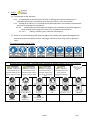
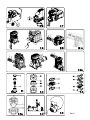
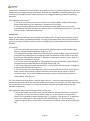
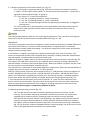
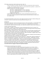
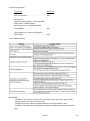
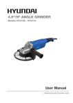
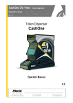
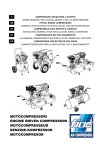
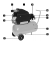
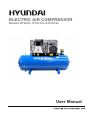
ELECTRIC AIR COMPRESSOR
Models HY3050, HY30100 & HY3150
User Manual
CONTENTS
TITLE
PAGE No
1. SAFETY
3
2. PARTS
4/5
3. APPLICATION
6
4. INSTALLATION INSTRUCTIONS
6
5. ADDITIONAL SAFETY
6/8
6. INSTALLATION & COMISSIONING
9/10
7. TECHNICAL DATA
11
8. CLEANING & MAINTENANCE
11/12
9. DISPOSAL & RECYCLING
12
10. TROUBLLESHOOTING
13
11. GENPOWER CONTACT DETAILS
14
12. DECLARATIONS of CONFORMITY
15
PAGE 2
Rev 2
1. SAFETY.
1.1. The operator of the machine;
1.1.1. Is responsible for and has a duty of care in making sure that the compressor is
operated safely and in accordance with the instructions in this user manual.
1.1.2. Should never leave it in a condition which would allow an untrained or unauthorised
person/s to operate this compressor.
1.1.2.1. Should take care and show due diligence for the safety of and with regard to
those around whilst using the machine, to include but not limited to;
1.1.2.1.1.
Elderly, children, pets, livestock and property.
1.2. Some or all of the following PPE, Warning Signs and symbols may appear throughout this
manual and you must adhere to their warning/s. Failure to do so may result in personal
injury.
Personal Protective clothing (PPE)
Warning Signs and Symbols – FOLLOW safety messages to avoid or reduce risk of injury or death.
DANGER - indicates a
hazard which if not
avoided could result in
serious injury or death.
GOGGLES
WARNING - indicates a
hazard which if not
avoided could result in
serious injury or death.
DO NOT OPEN
WHEN IN USE
CAUTION - indicates a
hazard which if not
avoided might result
in minor or moderate
injury.
NOTE - indicates a
situation that could
easily result in
equipment damage.
READ MANUAL
RISK OF ACCIDENTAL
START-UP
PAGE 3
Rev 2
1.3. Electrical Safety.
1.3.1. Electricity can kill - never work on LIVE/ENERGISED equipment.
1.3.2. Identify electrical isolation method and always isolate all electrical supplies,
prior to carrying out any maintenance work.
1.3.3. Prior to use and with all electrical supplies isolated check all electrical cables,
plugs and connections for the following.
Are intact and have no signs of damage, to include but not limited to
1.3.3.1.
bare wires, chaffing, cuts and loose wiring. If there are any signs of damage,
the damaged item should be taken out of service until the damage has been
repaired by an electrically competent person.
1.3.4. All trailing cables should be routed so as not to cause any kind of trip hazard.
1.5.
1.6.
Never work on or near electricity with wet hands, wet clothing, and wet gloves.
PAGE 4
Rev 2
2. UNPACKING - USAGE INSTRUCTION.
�
�
��
� � �
�
� �
�
�� PAGE 5
�� Rev 2
�� 14
15 17 16 19 18 20 21 22 PAGE 6
23 24 Rev 2
25 ��
��� �� �� �� ��
��� ��
��� �� PAGE 7
�� �� �� Rev 2
�� �� 3. PART LOCATIONS
5
6
4
7
8
3
2
1
9
10
12
11
1.
2.
3.
4.
5.
6.
7.
8.
9.
10.
11.
12.
DIRECT COMPRESSED AIR OUTLET.
TANK.
PRESSURE REDUCER.
BELT GUARD.
COMRESSOR UNIT.
ELECTRIC MOTOR.
PRESSURE SWITCH.
PRESSURE GUAGE.
PIVOT WHEEL.
CONDENSATE DRAIN.
WHEEL.
CHECK VALVE.
PAGE 8
Rev 2
4. SPECIFIC SAFETY
Read and understand all of the operating instructions, safety precautions and warnings in the
Instruction Manual before operating or maintaining this compressor.
Most accidents that result from compressor operation and maintenance are caused by the
failure to observe basic safety rules or precautions. An accident can often be avoided by
recognizing a potentially hazardous situation before it occurs, and by observing appropriate
safety procedures.
Basic safety precautions are outlined in the “SAFETY” section of this Instruction Manual and in
the sections which contain the operation and maintenance instructions.
Hazards that must be avoided to prevent bodily injury or machine damage are identified by
WARNINGS on the compressor and in this Instruction Manual.
Never use this compressor in a manner that has not been specifically recommended by
manufacturer, unless you first confirm that the planned use will be safe for you and others.
SAFETY
IMPORTANT SAFETY INSTRUCTIONS FOR USE OF THE COMPRESSOR.
Death or serious bodily injury could result from improper or unsafe use of compressor. To
avoid these risks, follow these basic safety instructions.
READ ALL INSTRUCTIONS
4.1 Never touch moving parts Never place your hands, fingers or other body parts near the
compressor’s moving parts.
4.2 Never operate without all the guards in place. Never operate this compressor without all
guards or safety features in place and in proper working order. If maintenance or servicing
requires the removal of a guard or safety features, be sure to replace the guards or safety
feature before resuming operation of the compressor.
4.3 Always wear eye protection. Always wear safety goggles or equivalent eye protection.
Compressed air must never be aimed at anyone or any part of the body.
4.4 Protect yourself against electric shocks. Prevent body contact with grounded surfaces such
as pipes, radiators, ranges and refrigeration enclosures. Never operate the compressor in
damp or wet locations.
4.5 Disconnect the compressor. Always disconnect the compressor from the power source and
remove the compressed air from the air tank before servicing, inspecting, maintaining,
cleaning, replacing or checking any parts.
4.6 Avoid unintentional satrting. DO NOT carry or move the compressor while it is connected
to its power source or when the air tank is filled with compressed air. Be sure the knob of the
pressure switch in the “OFF” position before connecting the compressro to its power source.
4.7 Store the compressor properly. When not in use, the compressor should be stored in dry
place. Keep out of reach of children. Lock the storage area.
4.8 Keep work area clean. Cluttered areas invite injurues. Clear all work areas of unnecessary
tools, debris, furniture etc.
4.9 Keep children away. All visitors should be kept safely away from work area.
4.10 Dress porperly. DO NOT wear loose clothing or jewerly. They can be caught in moving
parts. Wear protective hair covering to contain long hair.
4.11 DO NOT abuse the power lead. Never yank it to disconnect from receptable. Keep power
lead from heat, oil and sharp edges.
PAGE 9
Rev 2
4.12 Maintain compressor with care. Follow instructions for lubricating. Inspect power leads
periodically and if damaged, have repaired by authorised service facility. Inspect extension
leads periodically and replace if damaged.
4.13 Outdoor extension leads. When compressor in used outdoors, use only extension leads
intended for use outdoors and so marked.
4.14 Stay alert. Watch what you are doing. Use common sense. DO NOT operatecompressor
when you are tired. Compressor should never be used by you if you are under the influence of
alcohol, drugs or medication that makes you drowsy.
4.15 Check for damaged parts and air leaks. Before using the compressor, if a guard or other
part is damaged it should be carefully checked to determine that it will operate properly and
perform its intended function.
Check for alignment of moving parts, binding of moving parts, breakage of parts, mounting, air
leak, and any other conditions that may affect its operation. A guard or other part that is
damaged should be properly repaired or replaced by an authorised service center unless
otherwise indicated elsewhere in this instruction manual. Have defective pressure switches
replaced by authorised service center. DO NOT use compressor if switch does not turn it on
and off.
4.16 Handle compressor correctly. Operate the compressor according to the instructions
provided herein. Never allow the compressor to be operated by children, individuals unfamiliar
with its operation or unauthorised personnel.
4.17 Keep all screws, bolts and covers tight and in place. Keep all screws, bolts, and covers
tightly mounted. Check their condtion periodically.
4.18 Keep motor vent clean. The motor air vent must be kept clean so that air can freely flow
at all times. Check for dust build-up frequently.
4.19 Always operate compressor at its rated voltage. Operate the compressor at voltages
specified on their nameplates. If using the compressor at a higher voltage than the rated
voltage, it will result in abnormally fast motor revolution and may damage the unit and burn
out the motor.
4.20 Never use a compressor which has defects or is operating abnormally. If the compressor
appears to be operating unusually, making strange noises, or otherwise appears defective,
stop using it immediately and arrange for repairs by a authorised service center.
4.21 DO NOT wipe plastic parts with sovents. Solvents such as petrol, thinners, benzine, carbon
tetrachloride, and alcohol may damage and crack plastic parts. DO NOT wipe them with such
solvents. Wipe plastic parts with a soft cloth light dampened with soapy water and dry
thoroughly.
4.22 Use only genuine replacement parts. Non genuine replacement parts may void your
warranty and can lead to malfunction and result in injuries. Genuine parts are available from
your dealer.
4.23 DO NOT modify the compressor. DO NOT modify the compressor. Always contact the
authorised service center for any repairs. Unauthorised modification may not only impair the
compressor performance but may also result in accident or injury to repair personnel who do
not have the required knowledge and technical expertise to perform the repair operations
correctly.
4.24 Turn off the pressure switch when the compressor is not in use. When the compressor is
not it use, turn the knob of the pressure switch OFF, disconnect it from the power source and
open the drain cock to discharge the compressed air from the air tank.
4.25 Never touch hot surface. To reduce the risk of burns, DO NOT touch tubes, heads, cylinder
and motors.
PAGE 10
Rev 2
4.26 DO NOT direct the air stream at body. DO NOT direct air stream at persons or animals.
There is a risk of injury, by directing air stream at persons or animals.
4.27 Drain tank. Drain tank daily or after 4 hours of use. Open drain fitting and tilt compressor
to empty accumulated water.
4.28 DO NOT stop compressor by pulling out the plug. Use the "AUTO/OFF" of pressure switch.
4.29 Only use recommended air handling parts acceptable for a pressure not less than 125 Psi
(8.6 Bar). Risk of bursting. Use only recommended air handling parts acceptable for pressures
not less than 125 psi (8.6 bar).
4.30 Replacement parts. When servicing use only identical replacement parts. Repairs should
be conducted only by authorised service center.
4.31 Grounding (Earthing) instructions.
4.31.1 This compressor should be grounded (earted) while in use to protect the
operator from electric shock.
4.31.2 The compressor is equipped with a three-conductor lead and three-pin
grounding (earthing) type plug to fit the proper grounding (earthing) type socket.
4.31.3 The green and yellow conductor in the lead is the grounding/earthing wire.
4.31.4 Never connect the green and yellow wire to a live terminal.
4.32 Extension leads.
4.32.1 Use only three-extension leads that have three-prin grounding (earthing) type
plugs and three-pole sockets that accept the compressor’s plug.
4.32.2 Replace or repair damaged lead. Make sure your extension lead is in good
condition. When using an extension lead, be sure to use one heavy enough to carry the current
your product will draw. An undersized lead will cause a drop in line voltage resulting in loss of
power and overheating. Tables below shows the correct size to use depending on lead length
and name plate ampere rating. If in doubt, use the next heavier gauge.
Avoid electrical shock hazard. Never use this compressor with a damaged or frayed electrical
leador extension lead. Inspect all electrical leads regularly. Never use in near water or in any
environment where electric shock is possible.
Tab.1 SECTION VALID FOR A MAX LENGTH OF 20 mt single-phase
CV
kW
220/230V
110/120V
mm2
mm2
0.75 – 1
0.65 – 0.7
1.5
2.5
1.5
1.1
2.5
4
2
1.5
2.5
4 –6
2.5 – 3
1.8 – 2.2
4
/
The diameter of the extension cable of the 3-phase compressors must be in
proportion to its length: see table (tab 2)
Tab. 2 SECTION VALID FOR A MAX LENGTH OF 20 mt three-phase
CV
kW
220/230V
380/400V
mm2
mm2
2–3–4
1.5 – 2.2 – 3
2.5
1.5
5.5
4
4
2
7.5
5.5
6
2.5
10
7.5
10
4
PAGE 11
Rev 2
5. OPERATION & MAINTENANCE
The information contained in this Instruction Manual is designed to assist you in the safe
operation and maintenance of the compressor. Some illustrations in this Instruction Manual may
show details or attachments that differ from those on your own compressor.
5.1 Installation.
5.1.1 Remove the compressor from its packing (fig.1), makes sure it is in perfect
condition, checking if it has been damaged during transport, and carry out the
following operations.
5.1.2 Fit the wheels and rubber tab on the tanks on which they are not already fitted,
observing the instructions in fig.2. In case of infiatable wheels, the maximum inflation
pressure must be of 1.6 bar (24 psi).
5.1.3 Position the compressor on a flat surface or with a maximum permissible
inclination of 10° (fig. 3), in a well aired place, protected against atmospheric agents a
and not in a place subject to explosion hazard.
5.1.4 If the surface is inclined and smooth, check if the compressor moves while in
operation – if it does, secure the wheels with two wedges.
5.1.5 If the surface is a bracket or a shelf top, make sure it cannot fall, securing it in a
suitable way.
5.1.6 To allow for good ventilation and efficient cooling, the compressor’s belt guard
must be at least 100 cm from any wall (fig. 4).
5.1.7 Compressors fitted on the tank, with fixed feet, should not be rigidly secured to
the ground. In this case, we advise you to fit 4 anti-vibration supports.
5.2 Instructions for use.
5.2.1 Take care to transport the compressor correctly, do not overturn it or lift it with
hooks or ropes (fig. 5 - 6)
5.2.2 Replace the plastic plug on the guard cover (fig. 7 - 8) with the oil level stick (fig.
9) or with the relevant breather plug (fig. 10), supplied with the instructions booklet.
5.2.3 Check oil level, consulting the reference marks on the stick (fig. 9) or the oil level
inspection window (fig. 11).
5.3 Electrical connections.
5.3.1 Single-phase compressors are supplied with an electrical cable and a three pin
earth plug. The compressor must be connected to a grounded power socket (fig.12).
5.3.2 Three-phase compressors (L1+L2+L3+PE) must be installed by a specialised
technician. Three-phase compressors are supplied without a plug. Connect a plug, with
screw-on grommet and securing collar (fig.13), to the cable, consulting the table below.
HP
2–3–4
kW
1.5 – 2.2 –3
Power supply volt/ph Plug model
220/380/3
230/400/3 16A 3 pole + ground
5.5 – 7.5 – 10
4 – 5.5 – 7.5
220/380/3
230/400/3 32A 3 pole + ground
PAGE 12
Rev 2
Compressors installed on the 500 lt tank, with capacity of HP7.5/ 55 kW and HP10/7.5 kW can be
supplied a star/triangle starting control unit, whereas the TANDEM (2 pumping elements on the
same tank) are supplied with a timed control unit for staggered starting of the two pumping
elements.
5.4 Installation instructions:
5.4.1 Secure the control unit box on a wall or on a fixed support, and provide it with a
power cable with plug, of a diameter in proportion to its length.
5.4.2 Any damage caused by incorrect connections of the power line to the mains,
automatically excludes warranty of electrical parts. To avoid connection errors, we advise
you to contact a specialised technician.
IMPORTANT:
Never use the ground (earth) wire instead of the neutral wire. The ground connection must be
made to meet safety standards(EN 60204). The plug of the power cable must not be used as a
switch, but must be fitted in a power socket controlled by a suitable differential switch (thermalbreaker).
5.5 Starting.
5.5.1 Check that the mains power matches that indicated on the electrical data-plate
(fig.14) – the permissible tolerance range is +/-5%.
5.5.2 When first starting compressors operating on 3-phase voltage, check the rotation
direction of the cooling fan by comparing it with the direction of the arrow on the belt
guard or on the protective housing. In the SILENT compressor, check if the air flows is in
the direction illustrated in fig.21A.
5.2.3 Turn or press into position “0” (according to the type of pressure switch fitted on
the appliance) the knob located on the upper section (fig. 15).
5.2.4 Fit the plug in the power socket (fig. 12 - 13) and start the compressor, turning the
pressure switch knob into position “I”.
5.2.5 The compressor is fully automatic, and is controlled by the pressure switch which
stops it when tank pressure reaches maximum value and restarts it when it falls to
minimum value. The pressure difference between maximum and minimum values is
usually about 2 bar (29 psi).
E.G. The compressor stops when it reaches 8 bar (116 psi – maximum operating pressure) and
restarts automatically when the pressure inside the tank drops to 6 bar (87 psi). After connecting
the compressor to the power line, load it to maximum pressure and check exactly how the
machine is operating.
5.6 Compressor with D type starting control unit (fig. 16) .
5.3.1 Fit the plug in the power socket (fig. 13) and turn the pressure switch to position
“I” (ON) (fig. 17). Turn the master power switch “A” on the control unit to position I –
power On is signalled by white indicator-light “E” going on. Turn switch “B” to position 1
to start the compressor. If the solenoid-valve indicator-light “D” and the motor (C)
indicator-light (C) go on in that order, this means the machine is operating correctly (fig.
18).
PAGE 13
Rev 2
5.7 Tandem compressors with timed control unit. (fig. 17).
5.7.1 Fit the plug in the power socket (fig. 13) and turn the pressure switch to position
“I” (ON). Turn the master power switch “A” on the control unit to position I – power On is
signalled by white indicator-light “E” going on.
5.7.2 Turn switch “B” to start the compressor.
5.7.2.1 Pos. 1 pumping element n. 1 only is operating
5.7.2.2 Pos. 2 pumping element n. 2 only is operating
5.7.2.3 Pos. 3 both pumping elements are operating simultaneously, at staggered
starting times.
5.7.3 The compressor is fully automatic, and is controlled by the pressure switch which
stops it when tank pressure reaches maximum value and restarts it when it falls to
minimum value.
The head/cylinder/delivery tube unit can reach high temperatures. Take care when working near
these parts, and do not touch them to avoid possible burns (fig. 18 - 19).
IMPORTANT
The electro-compressors must be connected to a power socket protected by a suitable differential
switch (thermal-breaker). The motor of GM-TR compressors is equipped with an automatic
thermal breaker located inside the winding – this stops the compressor when motor temperature
reaches excessively high values.
If the breaker is tripped, the compressors restarts automatically after 10 to 15 minutes. The
motors of compressor models VX are supplied with a manually resetting automatic amperometric
thermal-breaker, located outside the terminal board cover.
When the breaker is tripped, wait for a few minutes and then reset the breaker manually (fig. 20).
The motors of the AB series compressors are supplied with a manually resetting amperometric
thermal-breaker, located on the terminal board cover. When the breaker is tripped, wait for a few
minutes and then reset the breaker manually (fig. 20).
The safety davice is automatic in three-phase and silent compressors. When the thermal-breaker is
tripped, the pressure switch is released to “0” (OFF) position.
Wait for a few minutes and return the pressure switch to “I” (ON) position (with the exception of
models: AB 100/245-335 Three-phase - AB 150/ 245-335 Three-phase - AB 200/245-335 Threephase). For compressors supplied with a control unit, the thermal-breaker is installed inside the
control unit. When the thermal-breaker is tripped, observe the following procedure (fig. 22):
• Turn the switches on the control unit cover to position “0”, open the cover and press pushbutton 1 of the thermal-breaker. Close the cover of the control unit and restart the compressor,
observing the operations described in the paragraph “Starting compressors with control unit”.
The same instructions apply to compressors powered at 60 Hz.
5.8 Adjusting the operating pressure (fig. 23).
5.8.1 You do not have to use the maximum operating pressure at all times. On the
contrary, the pneumatic tool being used often requires less pressure. On compressors
supplied with a pressure reducer, operating pressure must be correctly adjusted.
5.8.2 Release the pressure reducer knob by pulling it up, adjust pressure to the required
value by turning the knob clockwise to increase pressure and anti-clockwise to reduce it.
5.8.3 When you have obtained optimum pressure, lock the knob by pressing it downward
(fig. 23). For pressure reducers equipped without a pressure gauge, the set pressure can be
seen on the graduated scale located on the reducer body.
PAGE 14
Rev 2
5.8 Tandem compressors with timed control unit. (fig. 17).
5.8.1 Fit the plug in the power socket (fig. 13) and turn the pressure switch to position
“I” (ON). Turn the master power switch “A” on the control unit to position I – power On is
signalled by white indicator-light “E” going on.
5.8.2 Turn switch “B” to start the compressor.
5.8.2.1 Pos. 1 pumping element n. 1 only is operating
5.8.2.2 Pos. 2 pumping element n. 2 only is operating
5.8.2.3 Pos. 3 both pumping elements are operating simultaneously, at
staggered starting times.
5.8.3 The compressor is fully automatic, and is controlled by the pressure switch
which stops it when tank pressure reaches maximum value and restarts it when it falls
to minimum value.
The head/cylinder/delivery tube unit can reach high temperatures. Take care when working near
these parts, and do not touch them to avoid possible burns (fig. 18 - 19).
IMPORTANT
The electro-compressors must be connected to a power socket protected by a suitable differential
switch (thermal-breaker). The motor of GM-TR compressors is equipped with an automatic
thermal breaker located inside the winding – this stops the compressor when motor temperature
reaches excessively high values.
If the breaker is tripped, the compressors restarts automatically after 10 to 15 minutes. The
motors of compressor models VX are supplied with a manually resetting automatic amperometric
thermal-breaker, located outside the terminal board cover.
When the breaker is tripped, wait for a few minutes and then reset the breaker manually (fig. 20).
The motors of the AB series compressors are supplied with a manually resetting amperometric
thermal-breaker, located on the terminal board cover. When the breaker is tripped, wait for a few
minutes and then reset the breaker manually (fig. 20).
The safety davice is automatic in three-phase and silent compressors. When the thermal-breaker is
tripped, the pressure switch is released to “0” (OFF) position.
Wait for a few minutes and return the pressure switch to “I” (ON) position (with the exception of
models: AB 100/245-335 Three-phase - AB 150/ 245-335 Three-phase - AB 200/245-335 Threephase). For compressors supplied with a control unit, the thermal-breaker is installed inside the
control unit. When the thermal-breaker is tripped, observe the following procedure (fig. 22):
• Turn the switches on the control unit cover to position “0”, open the cover and press pushbutton 1 of the thermal-breaker. Close the cover of the control unit and restart the compressor,
observing the operations described in the paragraph “Starting compressors with control unit”.
The same instructions apply to compressors powered at 60 Hz.
5.9 Adjusting the operating pressure (fig. 23).
5.9.1 You do not have to use the maximum operating pressure at all times. On the
contrary, the pneumatic tool being used often requires less pressure. On compressors
supplied with a pressure reducer, operating pressure must be correctly adjusted.
5.9.2 Release the pressure reducer knob by pulling it up, adjust pressure to the required
value by turning the knob clockwise to increase pressure and anti-clockwise to reduce it.
5.9.3 When you have obtained optimum pressure, lock the knob by pressing it downward
(fig. 23). For pressure reducers equipped without a pressure gauge, the set pressure can be
seen on the graduated scale located on the reducer body.
PAGE 15
Rev 2
5.10 Tandem compressors with timed control unit. (fig. 17).
5.10.1 Fit the plug in the power socket (fig. 13) and turn the pressure switch to position
“I” (ON). Turn the master power switch “A” on the control unit to position I – power On is
signalled by white indicator-light “E” going on.
5.10.2 Turn switch “B” to start the compressor.
5.10.2.1 Pos. 1 pumping element n. 1 only is operating
5.10.2.2 Pos. 2 pumping element n. 2 only is operating
5.10.2.3 Pos. 3 both pumping elements are operating simultaneously, at
staggered starting times.
5.10.3 The compressor is fully automatic, and is controlled by the pressure switch
which stops it when tank pressure reaches maximum value and restarts it when it falls
to minimum value.
The head/cylinder/delivery tube unit can reach high temperatures. Take care when working near
these parts, and do not touch them to avoid possible burns (fig. 18 - 19).
IMPORTANT
The electro-compressors must be connected to a power socket protected by a suitable differential
switch (thermal-breaker). The motor of GM-TR compressors is equipped with an automatic
thermal breaker located inside the winding – this stops the compressor when motor temperature
reaches excessively high values.
If the breaker is tripped, the compressors restarts automatically after 10 to 15 minutes. The
motors of compressor models VX are supplied with a manually resetting automatic amperometric
thermal-breaker, located outside the terminal board cover.
When the breaker is tripped, wait for a few minutes and then reset the breaker manually (fig. 20).
The motors of the AB series compressors are supplied with a manually resetting amperometric
thermal-breaker, located on the terminal board cover. When the breaker is tripped, wait for a few
minutes and then reset the breaker manually (fig. 20).
The safety davice is automatic in three-phase and silent compressors. When the thermal-breaker is
tripped, the pressure switch is released to “0” (OFF) position.
Wait for a few minutes and return the pressure switch to “I” (ON) position (with the exception of
models: AB 100/245-335 Three-phase - AB 150/ 245-335 Three-phase - AB 200/245-335 Threephase). For compressors supplied with a control unit, the thermal-breaker is installed inside the
control unit. When the thermal-breaker is tripped, observe the following procedure (fig. 22):
• Turn the switches on the control unit cover to position “0”, open the cover and press pushbutton 1 of the thermal-breaker. Close the cover of the control unit and restart the compressor,
observing the operations described in the paragraph “Starting compressors with control unit”.
The same instructions apply to compressors powered at 60 Hz.
5.11 Adjusting the operating pressure (fig. 23).
5.11.1 You do not have to use the maximum operating pressure at all times. On the
contrary, the pneumatic tool being used often requires less pressure. On compressors
supplied with a pressure reducer, operating pressure must be correctly adjusted.
5.11.2 Release the pressure reducer knob by pulling it up, adjust pressure to the required
value by turning the knob clockwise to increase pressure and anti-clockwise to reduce it.
5.11.3 When you have obtained optimum pressure, lock the knob by pressing it downward
(fig. 23). For pressure reducers equipped without a pressure gauge, the set pressure can be
seen on the graduated scale located on the reducer body.
PAGE 16
Rev 2
5.11.4 On pressure reducers equipped with a pressure gauge, pressure can be seen on
the gauge itself.
Some pressure regulators do not have "push to lock", therefore simply turn the knob to adjust
the pressure.
5.12 Maintenance.
Before attempting any maintenance jobs on the compressor, make sure of the following:
Master power switch in position “0”.
Pressure switch and the control unit switches all off, in position “0”.
No pressure in the air tank.
5.12.1 Every 50 hours of duty: we advise you to dismantle the suction filter and clean the
filtering element by blowing compressed air on it (fig. 24).
5.12.2 It is recommended to replace the filter element at least once if the compressor
operates in a clean environment, but more frequently if in a dusty environment.
In the “red-head” models (fig. 25) (TR200 – TR255), the suction filter is located internally
under the conveying cover (read-head). Unscrew the three cover securing screws,
remove the cover from the guard joint, remove the filter from its seat, and begin
cleaning, blowing compressed air in opposite to normal flow direction.
In the Silent model, the filtering element can be replaced by taking off the soundproofing
cabinet and proceeding in the same way as for the AB models (fig.29A).
5.12.3 The compressor generates condensate water which accumulates in the tank.
5.12.4 The condensate in the tank must be drained at least once a week, by opening the
drain tap (fig. 26) under the tank.
5.12.5 Take care if there is compressed air inside the cylinder, and water could flow out
with considerable force. Recommended pressure: 1 – 2 bar max.
5.12.6 Condensate of compressors that are oil lubricated must not be drained into the
sewer or dispersed in the environment as it contains oil.
5.13 Oil changes and Topping up with oil.
5.13.1 The compressor is filled with synthetic oil “FIAC Oil Synthesis”.
5.13.2 We recommend a full change of oil in the pumping element within the first 100
hours of duty.
5.13.3 The soundproofing cabinet is to be taken off first in the Silent model (fig.29A).
5.13.4 Unscrew the oil drain plug on the housing cover, allow all the oil to flow out, and
re-screw the plug (fig. 27 - 28).
5.13.5 Pour oil into the upper hole of the housing cover (fig. 29 - 30) until it reaches the
level indicated on the stick (fig. 9) or indicator (fig. 11)
5.13.6 Pour oil into the upper hole of the head (fig. 30) in belt assisted units designed for
topping up in that area.
5.13.7 For the GM203 series, take the cap off and pour in 85 grams of oil directly from
the bottle (see fig. 30a).
5.13.8 Once a week: check oil level of the pumping element (fig. 11) and see if it needs
topping up.
5.13.9 For operation at ambient temperature in the range -5°C to +40°C, use synthetic
oil. The advantage of this oil is that is does not lose its characteristics either in winter or
summer.
5.13.10 DO NOT drain used oil into the sewer or dispose of it in the environment.
PAGE 17
Rev 2
5.13 Oil change table.
Type of oil
Hours run
FIAC oil synthesis . . . . . . . . . . . . . . . . . . . . . . 500
Synthetic oil:
AGIP Sint 2000 Evolution - BP Visco 5000
ESSO Ultron - MOBIL Mobil 1
NILS Dimension S - NUOVA STILMOIL
Arrow5W50 . . . . . . . . . . . . . . . . . . . . . . . . . . . 400
Other types of oil: mineral multigrade;
SAE15 W40 . . . . . . . . . . . . . . . . . . . . . . . . . . . 100
5.14 Troubleshooting.
IMPORTANT
- DO NOT on any account unscrew any connection while the tank is pressurised.
- Always check if the tank is pressure free.
- DO NOT drill holes, weld or purposely deform the compressed air tank.
- DO NOT do any jobs on the compressor unless you have disconnected the power
plug.
PAGE 18
Rev 2
- Temperature in operating ambient: 0°C +35°C.
- DO NOT aim jets of water or inflammable liquids on the compressor.
- DO NOT place inflammable objects near the compressor.
- During down-times, turn the pressure switch to position “0” (OFF).
- Never aim the air jet at people or animals (fig. 34)
- DO NOT transport the compressor while the tank is pressurised.
- Be careful with regard to some parts of the compressor such as the head and delivery tubes, as
they can reach high temperatures. DO NOT touch these parts to avoid burns.(fig. 18 - 19).
- Transport the compressor, lifting or pulling it with the appropriate grips or handles (fig. 4 - 6).
- Keep children and animals well away from the machine operating area.
- If using the compressor for painting:
DO NOT work in closed environments or near to naked flames.
Make sure there is adequate exchange of air at the place of work.
Protect your nose and mouth with an appropriate mask. (fig. 35).
- If the electrical cable or plug are damaged, do not use the compressor and contact an
authorised service centre to replace the faulty element with an original spare part.
- If the compressor is located on a shelf or on a top above floor height, it must be secured to
prevent it falling while in operation.
- DO NOT put objects or your hands inside the protective grilles to avoid injury to yourself or
damaging the compressor. (fig. 36)
- When you have finished using the compressor, always remove the plug from the power socket.
Hints for efficient operation.
For efficient operation of the machineat full continuing load and maximum operating pressure ,
make sure the temperature of the work environment indoors does not exceed +25°C.
We adivse you to use the compressor at 70% maximum duty per hour, as this make for efficient
operation of the product in the long term.
5.16 Storing the compressor.
5.16.1 During the time that the compressor is unpacked store it in a dry place and a
temperature of between +5°C and + 45°C and sheltered away from the weather.
5.16.2 For the whole time that the compressor is not used after unpacking it, while waiting
to start it up place sheets over it to protect it from dust, which may settle on the
components.
5.16.3 The oil is to be replaced and the operational efficiency of the compressor is to be
checked if it is not used for long periods.
5.17 Pneumatic connections.
5.17.1 Make sure you use pneumatic tubes for compressed air with maximum
characteristics that are adequate for the compressor. DO NOT repair faulty tubes.
PAGE 19
Rev 2
6. SPECIFICATION
Model
Voltage - V
Number of phases
Frequency – Hz
Connection method/Cable length m
Motor power hp/kw
Rated Speed (motor) – RPM
Maximum Pressure - PSi/Bar
Cut-out Pressure - PSi/Bar
Cut-in Pressure - PSi/Bar
Tank Capacity - L
Free air delivery - CFM - L/min
Displacement - CFM/L/min
Air Outlet
Output pressure regulation type
Drive type
Overall Unit Dimensions L x W x H mm
Net Weight - kg
Tank material
HY3050.
230
1
50
3 pin plug - BS1363A
3/2.25
2800
145/10
128/8.8
87/6
50
9/255
13/368
Valve Tap
Fixed
Belt
1010 x 360 x 730
55
Rolled steel
HY3150.
230
1
50
3 pin plug - BS1363A
3/2.25
2800
145/10
128/8.8
87/6
150
9/255
13/368
Valve Tap
Fixed
Belt
1350 x 540 x 1040
107
Rolled steel
HY30100.
230
1
50
3 pin plug - BS1363A
3/2.25
2800
145/10
128/8.8
87/6
100
9/255
13/368
Valve Tap
Fixed
Belt
1100 x 400 x 830
64
Rolled steel
7. WIRING DIAGRAMS
7.1 Symbols.
A
P
T
TM
1-2-3-4
C
M
AU
AM
L
N
=
=
=
=
=
=
=
=
=
=
=
=
Power supply.
Pressure switch .
Automatic thermal protection switch.
Manual amperometric protection switch.
Wire connection terminals.
Condensor/Capacitor.
Motor.
Auxiliary winding.
Start winding.
Live.
Neutral.
Earth.
PAGE 20
Rev 2
7. GENPOWER CONTACT DETAILS
7.1 Postal address;
Genpower Limited, Isaac Way, Pembroke Dock, Pembrokeshire, SA72 4RW, UK.
7.2 Telephone and Fax contact numbers;
Office +44 (0) 1646 687880.
Fax +44 (0) 1646 686198.
7.3 Email contact;
Techinical - [email protected]
7.4 Web site;
www.hyundaipowerequipment.co.uk
8. DECLARATIONS of CONFORMITY.
8.1 Genpower Ltd confirms that this Hyundai product conform to the following CE
directives.
2004/108/EC EMC Directive
2006/42/EC Machinery Directive
2006/95/EC Low Voltage Directive
2009/105/EC Simple Pressure Directive
2000/14/EC Outdoor Noise Directive
PAGE 21
Rev 2
PAGE 22
Rev 2
PAGE 23
Rev 2
GENPOWER LTD
Isaac Way, London Road
Pembroke Dock, UNITED KINGDOM, SA72 4RW
T: +44 (0) 1646 687 880 F: +44 (0) 1646 686 198
E: [email protected]
www.hyundaipowerequipment.co.uk