1
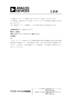
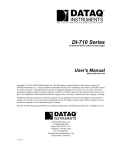
a
MicroConverter® Products
ADuC812 User’s Manual
Revision Draft.05
® MicroConverter is a Registered Trademark of Analog Devices, Inc.
™ QuickStart is a Trademark of Analog Devices, Inc.
® SPI is a Registered Trademark of Motorola, Inc.
® I2C is a Registered Trademark of Philips Semiconductor, Inc.
Information furnished by Analog Devices is believed to be accurate and reliable. However, no responsibility is
assumed by Analog Devices for its use, nor for any infringements of patents or other rights of third parties which
may result from its use. No license is granted by implication or otherwise under any patent or patent rights of
Analog Devices.
© Analog Devices, Inc., 2000
One Technology Way, P.O. Box 9106, Norwood, MA 02062-9106, U.S.A.
Tel: 617-329-4700
Fax: 617-326-8703
CONTENTS:
Preface
Chapter 1
Chapter 2
Chapter 3
Chapter 4
Appendices
a
Hardware Design Guide
Microcontroller Core
Programmer’s Guide
Other Modes of Operation
4
5
(in progress)
(in progress)
(in progress)
(in progress)
3
Preface
Analog Devices Inc. designs and manufacturers a broad line of linear, mixed signal and digital signal processing
integrated circuits. Analog Devices is recognized as an industry leader in the innovation and design of highperformance analog products and digital signal processing solutions. Find out more about Analog Devices from
our web site - www.analog.com.
Analog Devices' new MicroConverter products feature a unique integration of technologies combining highresolution data conversion with on-chip microcontroller and nonvolatile memory functionality. Together, these
features make up the world's first high precision data acquisition system on a chip.
This User's Manual details both the hardware and software features of the ADuC812 MicroConverter. The
intended audience is both the software programmer and hardware/system designer.
Additional documentation, including technical datasheets, technical notes and quick reference guides should be
used to supplement this text. This additional documentation can be found at the Analog Devices MicroConverter
web site. - www.analog.com/microconverter.
Customer Service and Technical Support:
For product marketing information or technical support, contact any Analog Devices sales office or authorized
distributor.
For applications engineering assistance, please use the following contacts:
North America:
Call
800-ANALOG-D (800-262-5643)
Email [email protected]
Europe:
Call
353-61-495969
Email [email protected]
Rest of World:
Call
781-937-1428
Email [email protected]
4
a
Chapter 1
Hardware Design Guide
1.1
1.2
1.3
1.4
1.5
1.6
1.7
1.8
1.9
1.10
1.11
1.12
a
Brief Overview of the ADuC812
Driving the A/D Converter
Voltage Reference Connections
The D/A Converter Outputs
Clock Oscillator
External Memory Interface
I/O Ports
Reset & POR (Power-On Reset)
Power Supplies
Grounding, Board Layout, Etc.
Other Hardware Considerations
Pin Functions
6
7
8
9
11
11
13
16
17
18
20
22
5
hardware
CONVST
23
ADC0
ADC1
ADC2
ADC3
ADC4
ADC5
ADC6
ADC7
1
2
3
4
11
12
13
14
P0.0
P0.1
P0.2
P0.3
P0.4
P0.5
P0.6
P0.7
P1.0
P1.1
P1.2
P1.3
P1.4
P1.5
P1.6
P1.7
P2.0
P2.1
P2.2
P2.3
P2.4
P2.5
P2.6
P2.7
P3.0
P3.1
P3.2
P3.3
P3.4
P3.5
P3.6
P3.7
43
44
45
46
49
50
51
52
1
2
3
4
11
12
13
14
28
29
30
31
36
37
38
39
16
17
18
19
22
23
24
25
ADuC812 User’s Manual
AIN
MUX
CREF
7
ADC
control
&
calibration
12bit ADC
T/H
Flash/EE
9
DAC0
DAC1
BUF
10
DAC1
22
T0
23
T1
1
T2
2
T2EX
16bit
counter
timers
8052
MCU
core
watchdog
timer
power supply
monitor
downloader
debugger
BUF
BUF
256 x 8
user RAM
Flash/EE
8K x 8
program
DAC1
DAC
control
640 x 8
data
(-3 mV/oC)
2.5V
bandgap
reference
8
640 bytes Flash/EE data
memory, and 256 bytes
data SRAM on-chip.
ADuC812
TEMP
sensor
VREF
1 – Hardware Design Guide
Additional
MCU
support
functions
include
Watchdog
Timer, Power Supply
Monitor, and ADC
DMA functions.
32
Programmable I/O lines
plus
I2C-compatible,
SPI, and UART Serial
Port I/O are provided for
multiprocessor
interfaces
and
I/O
expansion.
The Programmable 8051-compatible core is
supported by 8K bytes Flash/EE program memory,
6
12
32
33
SS
XTAL1
XTAL2
42
41
40
15
ALE
PSEN
EA
RESET
The ADuC812 is a fully integrated 12-bit data
acquisition system incorporating a high performance
self-calibrating multichannel ADC, two 12-bit
DACs, and a programmable 8-bit (8051-compatible)
MCU on a single chip.
26
27
19
17
1.1 Brief Overview of the ADuC812
synchronous
serial interface
(SPI or I2C)
SCLOCK
SDATA / MOSI
MISO
16
TxD
21
35
47
DGND
RxD
20
34
48
6
DVDD
5
AVDD
AGND
single-pin
emulator
Normal,
idle,
and
power-down operating
OSC
modes for both the
MCU core and analog
converters allow for
flexible
power
management schemes.
The part is specified for
3V and 5V operation
Figure 1 – Functional Block Diagram
over
the
industrial
temperature range (This chapter is more than an architectural overview.
40°C to +85°C) and is available in a 52-lead, plastic
It, along with the product datasheet, should be
quad flatpack package.
thought of as a hardware designer’s primary source
of information on the ADuC812. Future chapters
The ADC conversion block incorporates a 5µs, 12will focus on integrated functions largely from a
bit, A/D converter. Multiplexer and track/hold
software configuration perspective. This chapter
functions are integrated into the ADC section to
details
the
significant
hardware
design
allow accurate sampling of up to eight external
considerations required to facilitate successful
inputs plus a ninth input from the on-chip
integration of the ADuC812 into any hardware
temperature sensor. Trigger sources for the ADC
system.
converter can come from an external source or from
one of three software triggers from the MCU.
asynchronous
serial port
(UART)
18
INT0
19
INT1
Two integrated 12-bit DACs provide rail-to-rail
buffered analog outputs and can be individually
configured for 0-to-VDD or 0-to-VREF output voltage
range.
The reference source for the ADC and DACs can
come from an external voltage reference or from the
on-chip 2.5V bandgap reference.
All analog peripherals are fully configurable through
the on-chip MCU via a simple SFR interface.
a
ADuC812 User’s Manual
1.2 Driving the A/D Converter
The ADC incorporates a successive approximation
(SAR) architecture involving a charge-sampled input
stage. Figure 2 shows the equivalent circuit of the
analog input section. Each ADC conversion is
divided into two distinct phases as defined by the
position of the switches in Figure 2. During the
sampling phase (with SW1 and SW2 in the “track”
position) a charge proportional to the voltage on the
analog input is developed across the input sampling
capacitor. During the conversion phase (with both
switches in the “hold” position) the capacitor DAC
is adjusted via internal SAR logic until the voltage
on node A is zero indicating that the sampled charge
on the input capacitor is balanced out by the charge
being output by the capacitor DAC. The digital
value finally contained in the SAR is then latched
out as the result of the ADC conversion. Control of
the SAR, and timing of acquisition and sampling
modes, is handled automatically by built-in ADC
control logic. Acquisition and conversion times are
also fully configurable under user control (see
Chapter 3).
1 – Hardware Design Guide
Note that whenever a new input channel is selected,
a residual charge from the 2pF sampling capacitor
places a transient on the newly selected input. The
signal source must be capable of recovering from
this transient before the sampling switches click into
“hold” mode. Delays can be inserted in software
(between channel selection and conversion request)
to account for input stage settling, but a hardware
solution will alleviate this burden from the software
design task and will ultimately result in a cleaner
system implementation. One hardware solution
would be to choose a very fast settling op amp to
drive each analog input. Such an op amp would
need to fully settle from a small signal transient in
less than 300ns in order to guarantee adequate
settling under all software configurations. A better
solution, recommended for use with any amplifier, is
shown in Figure 3.
ADuC812
51W
1
AIN0
0.01µF
ADuC812
AIN7
AIN0
TEMPERATURE
SENSOR
14
Figure 3 – Driving the Analog Inputs
1
200W
TRACK
SW1
CAPACITOR
DAC
HOLD
2pF
200W
NODE A
SW2
TRACK
AGND
HOLD
COMPARATOR
6
Figure 2 – Analog Input Equivalent Circuit
a
Though at first glance the circuit in Figure 3 may
look like a simple anti-aliasing filter, it actually
serves no such purpose since its corner frequency is
well above the Nyquist frequency, even at a 200kHz
sample rate. Though the R/C does helps to reject
some incoming high-frequency noise, its primary
function is to ensure that the transient demands of
the ADC input stage are met. It does so by
providing a capacitive bank from which the 2pF
sampling capacitor can draw its charge. Since the
0.01µF capacitor in Figure 3 is more than 4096
times the size of the 2pF sampling capacitor, its
voltage will not change by more than one count
(1/4096) of the 12-bit transfer function when the 2pF
charge from a previous channel is dumped onto it.
A larger capacitor can be used if desired, but not a
larger resistor (for reasons described below).
The Schottky diodes in Figure 3 may be necessary to
limit the voltage applied to the analog input pin as
7
ADuC812 User’s Manual
per the datasheet absolute maximum ratings. They
are not necessary if the op amp is powered from the
same supply as the ADuC812 since in that case the
op amp is unable to generate voltages above VDD or
below ground.
An op amp of some kind is necessary unless the
signal source is very low impedance to begin with.
DC leakage currents at the ADuC812’s analog
inputs can cause measurable DC errors with external
source impedances as little as 100Ω or so. To
ensure accurate ADC operation, keep the total
source impedance at each analog input less than
61Ω. Table 1 illustrates examples of how source
impedance can affect DC accuracy.
Source
Error from 1µA Error from 10µA
Impedance Leakage Current Leakage Current
61Ω
61µV = 0.1 LSB 610µV = 1 LSB
610Ω
610µV = 1 LSB 6.1mV = 10 LSB
Table 1 – DC Error due to Source Impedance
(assuming VREF = 2.5V)
Although Figure 3 shows the op amp operating at a
gain of 1, you can of course configure it for any gain
needed. Also, you can just as easily use an
instrumentation amplifier in its place to condition
differential signals. Use any modern amplifier that
is capable of delivering the signal (0 to VREF) with
minimal saturation. Some single-supply rail-to-rail
op-amps that are useful for this purpose include, but
are certainly not limited to, the ones given in Table
2. Check Analog Devices literature (CD ROM data
book, etc.) for details on these and other op amps
and instrumentation amps.
Op Amp Model
Characteristics
OP181/281/481
micropower
OP191/291/491
I/O good up to VDD, low cost
OP196/296/496
I/O to VDD, micropwr, low cost
OP183/283
high gain-bandwidth product
OP162/262/462
high GBP, micro package
AD820/822/824
FET input, low cost
AD823
FET input, high GBP
Table 2 – Some single-supply op amps
Keep in mind that the ADC’s transfer function is 0
to VREF, and any signal range lost to amplifier
saturation near ground will impact dynamic range.
Though the op amps in Table 2 are capable of
8
1 – Hardware Design Guide
delivering output signals very closely approaching
ground, no amplifier can deliver signals all the way
to ground when powered by a single supply.
Therefore, if a negative supply is available, you
might consider using it to power the front-end
amplifiers. If you do, however, be sure to include
the Schottky diodes shown in Figure 3 (or at least
the lower of the two diodes) to protect the analog
input from under-voltage conditions.
To summarize this section, use the circuit of Figure
3 to drive the analog input pins of the ADuC812.
Functional details of the ADC, including timing
specifics and software configuration, will be covered
in Chapter 3 of this manual.
1.3 Voltage Reference Connections
The on-chip 2.5V bandgap voltage reference can be
used as the reference source for the ADC and DACs.
In order to ensure the accuracy of the voltage
reference you must decouple both the VREF pin and
the CREF pin to ground with 0.1µF ceramic chip
capacitors as shown in Figure 4.
ADuC812
BUFFER
~50KW
2.5V
BANDGAP
REFERENCE
BUFFER
VREF
8
0.1µF
CREF
7
0.1µF
Figure 4 – Using the Internal Voltage Reference
The internal voltage reference can also be tapped
directly from the VREF pin, if desired, to drive
external circuitry. However, a buffer must be used
in this case to ensure that no current is drawn from
the VREF pin itself. The voltage on the CREF pin is
a
ADuC812 User’s Manual
1 – Hardware Design Guide
that of an internal node within the buffer block, and
its voltage is critical to ADC and DAC accuracy.
Do not connect anything to this pin except the
capacitor, and be sure to keep trace-lengths short on
the CREF capacitor, decoupling the node straight to
the underlying ground plane.
Operation of the ADC or DACs with a reference
voltage below 2.3V, however, may incur loss of
accuracy eventually resulting in missing codes or
non-monotonicity. For that reason, do not use a
reference voltage less than 2.3V.
The ADuC812 powers up with its internal voltage
reference in the “off” state. The voltage reference
turns on automatically whenever the ADC or either
DAC gets enabled in software. Once enabled, the
voltage reference requires approximately 65ms to
power up and settle to its specified value. Be sure
that your software allows this time to elapse before
initiating any conversions.
1.4 The D/A Converter Outputs
If an external voltage reference is preferred, simply
connect it to the VREF pin as shown in Figure 5 to
overdrive the internal voltage reference.
The on-chip D/A converter architecture consists of a
resistor string DAC followed by an output buffer
amplifier, the functional equivalent of which is
illustrated in Figure 6. Details of the actual DAC
architecture can be found in U.S. patent number
Features of this
5969657 (www.uspto.gov).
architecture
include
inherent
guaranteed
monotonicity and excellent differential linearity.
ADuC812
AVDD
ADuC812
VDD
~150KW
EXTERNAL
VOLTAGE
REFERENCE
2.5V
BANDGAP
REFERENCE
VREF
R
R
OUTPUT
BUFFER
R
8
DAC0
BUFFER
VREF
HIGH-Z
DISABLE
(from MCU)
8
0.1µF
R
CREF
7
R
0.1µF
Figure 5 – Using an External Voltage Reference
To ensure accurate ADC operation, the voltage
applied to VREF must be between 2.3V and AVDD. In
situations where analog input signals are
proportional to the power supply (such as some
strain-gage applications) it can be desirable to
connect the VREF pin directly to AVDD. In such a
configuration you must also connect the CREF pin
directly to AVDD to circumvent internal buffer
headroom limitations. This allows the ADC input
transfer function to accurately span the full range 0
to AVDD.
a
Figure 6 – Resistor String DAC
Functional Equivalent
As illustrated in Figure 6, the reference source for
each DAC is user selectable in software. It can be
either AVDD or VREF. In 0-to-AVDD mode, the DAC
output transfer function spans from 0V to the
voltage at the AVDD pin. In 0-to-VREF mode, the
DAC output transfer function spans from 0V to the
voltage at the VREF pin.
The DAC output buffer amplifier features a true railto-rail output stage implementation. This means
that, unloaded, each output is capable of swinging to
9
within less than 100mV of both AVDD and ground.
Moreover, the DAC’s linearity specification (when
driving a 10KΩ resistive load to ground) is
guaranteed1 through the full transfer function except
codes 0 to 48, and, in 0-to-AVDD mode only, codes
3995 to 4095. Linearity degradation near ground
and VDD is caused by saturation of the output
amplifier, and a general representation of its effects
(neglecting offset & gain error) is illustrated in
Figure 7. The dotted line in Figure 7 indicates the
ideal transfer function, and the solid line represents
what the transfer function might look like with
endpoint non-linearities due to saturation of the
output amplifier. Note that Figure 7 represents a
transfer function in 0-to-VDD mode only. In 0-toVREF mode (with VREF < VDD) the lower nonlinearity would be similar, but the upper portion of
the transfer function would follow the “ideal” line
right to the end (VREF in this case, not VDD), showing
no signs of endpoint linearity errors.
1 – Hardware Design Guide
voltage drops as long as the reference voltage
remains below the upper trace in the corresponding
figure. For example, if AVDD=3V & VREF=2.5V, the
high-side voltage will not be affected by loads less
than 5mA. But somewhere around 7mA the upper
curve in Figure 9 drops below 2.5V (VREF)
indicating that at these higher currents the output
will not be capable of reaching VREF.
5
DAC loaded with 0FFF hex
4
output voltage [V]
ADuC812 User’s Manual
3
2
1
DAC loaded with 0000 hex
0
0
5
10
15
source/sink current [mA]
Figure 8 – Source & Sink Current Capability
with VREF = VDD = 5V
VDD
VDD-50mV
VDD-100mV
3
100mV
50mV
0mV
000 hex
FFF hex
Figure 7 – Endpoint Non-linearities
due to Amplifier Saturation
output voltage [V]
DAC loaded with 0FFF hex
2
1
DAC loaded with 0000 hex
0
0
5
10
15
source/sink current [mA]
The endpoint non-linearities conceptually illustrated
in Figure 7 get worse as a function of output loading.
Most of the ADuC812’s datasheet specifications
assume a 10KΩ resistive load to ground at the DAC
output. As the output is forced to source or sink
more current, the nonlinear regions at the top or
bottom (respectively) of Figure 7 become larger.
With larger current demands, this can significantly
limit output voltage swing. Figure 8 & Figure 9
illustrate this behavior. It should be noted that the
upper trace in each of these figures is only valid for
an output range selection of 0-to-AVDD. In 0-toVREF mode, DAC loading will not cause high-side
1
Refer to ADuC812 datasheet.
10
Figure 9 – Source & Sink Current Capability
with VREF = VDD = 3V
The DAC output buffer also features a highimpedance disable function. In the chip’s default
power-on state, both DACs are disabled, and their
outputs are in a high-impedance state (or “tri-state”)
where they remain inactive until enabled in software.
This means that if a zero output is desired during
power-up or power-down transient conditions, then a
pull-down resistor must be added to each DAC
output. Assuming this resistor is in place, the DAC
outputs will remain at ground potential whenever the
DAC is disabled. However, each DAC output will
still spike briefly when you first apply power to the
chip, and again when each DAC is first enabled in
a
ADuC812 User’s Manual
software. Typical scope shots of these spikes are
given in Figure 10 and Figure 11 respectively.
1 – Hardware Design Guide
ADuC812
XTAL1
32
200µs/DIV
AVDD - 2V/DIV
33
XTAL2
DAC out - 500mV/DIV
Figure 12 – Using a Parallel Resonant Crystal
Figure 10 – DAC Output Spike
at Chip Power-Up
5µs/DIV, 1V/DIV
TO INTERNAL
TIMING CKTS
ADuC812
EXTERNAL
CLOCK
SOURCE
XTAL1
32
33
XTAL2
TO INTERNAL
TIMING CKTS
Figure 13 – Connecting an External Clock Source
Figure 11 – DAC Output Spike
at DAC Enable
1.5 Clock Oscillator
The clock source for the ADuC812 can come either
from an external source or from the internal clock
oscillator. To use the internal clock oscillator,
connect a parallel resonant crystal between pins 32
& 33, and connect a capacitor from each pin to
ground, as shown in Figure 12. The value of the
capacitors should be the value recommended by the
crystal manufacturer for use with that specific
crystal.
To use an external clock source to drive the
ADuC812, simply connect the clock source to pin 32
(XTAL1) and leave pin 33 (XTAL2) open. The
logic levels required at the XTAL1 input are
specified in the product datasheet under “Digital
Inputs”.
a
Whether using the internal oscillator or an external
clock source, the ADuC812’s specified operational
clock speed range is 400kHz to 16MHz. The core
itself is static, and will function all the way down to
DC. But at clock speeds slower than 400kHz, the
ADC will no longer function correctly. Therefore,
to ensure specified operation, use a clock frequency
of at least 400kHz, and no more than 16MHz.
1.6 External Memory Interface
In addition to its internal program and data
memories, the ADuC812 can access up to 64K bytes
of external program memory (ROM/PROM/etc.) and
up to 16M bytes of external data memory (SRAM).
To select from which code space (internal or
external program memory) to begin executing
instructions, tie the EA (external access) pin high or
low, respectively. When EA is high (pulled up to
VDD) user program execution will start at address 0
of the internal 8K Flash/EE code space. When EA
is low (tied to ground) user program execution will
start at address 0 of the external code space. In
11
ADuC812 User’s Manual
either case, addresses above 1FFF hex (8K) are
mapped to the external space, as shown in Figure 14.
1 – Hardware Design Guide
PSEN strobes the EPROM and the code byte is read
into the ADuC812. A detailed diagram of external
program memory read sequence timing is given in
the ADuC812 product datasheet.
FFFF hex
EXTERNAL
2000 hex
1FFF hex
EA=1
INTERNAL
EA=0
EXTERNAL
Note that program memory addresses are always 16
bits wide, even in cases where the actual amount of
program memory used is less than 64K bytes.
External program execution sacrifices two of the 8bit ports (P0 and P2) to the function of addressing
the program memory.
While executing from
external program memory, Ports 0 and 2 can be used
simultaneously for read/write access to external data
memory, but not for general purpose I/O.
0000 hex
Figure 14 – Program Memory Selection
Internal / External
Note that a second very important function of the
EA pin is described in the section on “Other
Hardware Considerations” near the end of this
chapter.
ADuC812
ADuC812
SRAM
P0
DATA
A0-A7
ALE
LATCH
P2
A8-A15
RD
WE
WR
OE
EPROM
P0
INSTR.
A0-A7
Figure 16 – External Data Memory Interface
for up to 64K Addressing
ALE
LATCH
P2
A8-A15
ADuC812
SRAM
P0
PSEN
DATA
OE
A0-A7
ALE
Figure 15 – External Program Memory Interface
LATCH
P2
External program memory (if used) must be
connected to the ADuC812 as illustrated in Figure
15. Note that 16 I/O lines (Ports 0 & 2) are
dedicated to bus functions during external program
memory fetches. Port 0 (P0) serves as a multiplexed
address/data bus. It emits the low byte of the
program counter (PCL) as an address, and then goes
into a float state awaiting the arrival of the code byte
from the program memory. During the time that the
low byte of the program counter is valid on P0, the
signal ALE (address latch enable) clocks this byte
into an address latch. Meanwhile, Port 2 (P2) emits
the high byte of the program counter (PCH). Then
12
A8-A15
A16-A24
LATCH
RD
WE
WR
OE
Figure 17 – External Data Memory Interface
for up to 16Meg Addressing
Though both external program memory and external
data memory are accessed by some of the same pins,
the two are completely independent of each other
a
ADuC812 User’s Manual
from a software point of view. For example, the
chip can read/write external data memory while
executing from external program memory.
Figure 16 shows a hardware configuration for
accessing up to 64K bytes of external RAM. This
interface is standard to any 8051 compatible MCU.
If access to more than 64K bytes of RAM is desired,
a feature unique to the ADuC812 allows addressing
up to 16M bytes of external RAM by simply adding
a latch as illustrated in Figure 17.
In either implementation, Port 0 (P0) serves as a
multiplexed address/data bus. It emits the low byte
of the data pointer (DPL) as an address, which gets
latched by a pulse of ALE prior to data being placed
on the bus by the ADuC812 (write operation) or the
SRAM (read operation). Port 2 (P2) provides the
data pointer page byte (DPP) to be latched by ALE,
followed by the data pointer high byte (DPH). If no
latch is connected to P2, then DPP is ignored by the
SRAM, and the 8051 standard of 64K byte external
data memory access is maintained.
Detailed timing diagrams of external program and
data memory read and write access can be found in
the ADuC812 product datasheet.
• “MOVX @DPTR” or “MOVC” instructions use
both Port 0 and Port 2. Just as above, the contents
of the P0 SFR are annihilated and replaced with
FF hex. The contents of the P2 SFR, however, are
retained, and the Port 2 pins will return to the state
defined by P2 as soon as the instruction is
complete (assuming that the next instruction cycle
doesn’t access external memory).
• Execution from external program memory uses
both Port 0 and Port 2. Again, the contents of the
P0 SFR get forced to FF hex. Again the contents
of the P2 SFR are retained, and Port 2 pins will
return to the state defined by P2 upon the first
machine cycle that doesn’t access external
memory.
All the Port 3 pins are multifunctional. They are not
only port pins, but also serve the functions of
various special features as listed in Table 3.
The alternate functions of Port 3 pins can only be
activated if the corresponding bit latch in the P3 SFR
contains a 1. Otherwise, the port pin is stuck at 0.
Pin
P3.0
1.7 I/O Ports
P3.1
Each of the four I/O ports on the ADuC812 features
a different implementation of drive/receive circuitry.
All ports except Port 1 are bi-directional, featuring
standard 8051/8052 functionality. The operation of
Port 1 is unique to the ADuC812.
P3.2
P3.3
As described briefly in the previous section, Ports 0
and 2 are used to access external memory. When
not accessing external memory, Ports 0 and 2 are
available for general-purpose input and output
functions, controlled by the special function registers
P0 and P2. The different types of external memory
accesses disrupt the standard I/O functions of Ports 0
and 2 in different ways. Specifically:
P3.6
P3.7
• “MOVX @Ri” instructions require only an 8-bit
address bus, so only Port 0 is used. The P2 SFR
goes untouched, and the Port 2 pins retain their
general-purpose I/O states. The contents of the P0
SFR, however, are annihilated and replaced by the
power-on default value of FF hex.
a
1 – Hardware Design Guide
P3.4
P3.5
Alternate Function
RxD (UART input port)
(or serial data I/O in mode 0)
TxD (UART output port)
(or serial clock output in mode 0)
INT0 (external interrupt 0)
INT1 (external interrupt 1)
MISO (SPI port “master-in / slave-out”)*
T0 (Timer/Counter 0 external input)
T1 (Timer/Counter 1 external input)
CONVST (ADC hardware convert-start)*
WR (external data memory write strobe)
RD (external data memory read strobe)
* The MISO and CONVST functions are specific to the
ADuC812. All other functions are standard to the 8052.
Table 3 – Port 3 Alternate Pin Functions
Port 3 pins are tested for greater sink current (8mA)
than other port pins, allowing direct drive of LED or
optocoupler devices. However, avoid sinking this
full current into more than a couple of pins at a time
during ADC conversions to prevent performance
degradation.
13
ADuC812 User’s Manual
The primary function of Port 1 pins on the
ADuC812 is as analog inputs. Writing ones to the
P1 SFR bits (the power-on default condition)
enables the Port 1 pins for analog input mode. Any
Port 1 pins not used for analog inputs can
alternatively be used for digital inputs by writing
zeros to the corresponding P1 SFR bits. Port 1 pins
have no output drivers and therefore cannot be used
as digital outputs.
Pin
P1.0
P1.1
P1.5
Alternate Function
T2 (Timer/Counter 2 external input)
T2EX (Timer/Counter 2 capture/reload
trigger)
SS (SPI port “slave-select”)*
* The SS function is specific to the ADuC812. The other two
functions are standard to the 8052.
Table 4 – Port 1 Alternate Pin Functions
1 – Hardware Design Guide
signal is low, thereby disabling the top FET.
External pull-up resistors are therefore required
when Port 0 pins are used as general-purpose
outputs.
When accessing external memory,
however, the CONTROL signal in Figure 18 goes
high, enabling push-pull operation of the output pin
from the internal address or data bus (ADDR/DATA
line). Therefore, no external pull-ups are required
on Port 0 in order for it to access external memory.
CONTROL
DVDD
ADDR/DATA
READ
LATCH
P0.x
pin
INTERNAL
BUS
D
WRITE
TO LATCH
CL Q
Q
LATCH
Three Port 1 pins are multifunctional. In addition to
providing analog or digital inputs, they serve the
special functions listed in Table 4.
READ
PIN
Figure 18 – Port 0
Bit Latch & I/O Buffer
Bit Latches & I/O Buffers
Figure 18 through Figure 22 show a typical bit latch
and I/O buffer in each of the four ports. The bit
latch (one bit in the port’s SFR) is represented as a
Type D flip-flop, which will clock in a value from
the internal bus in response to a “write to latch”
signal from the CPU. The Q output of the flip-flop
is placed on the internal bus in response to a “read
latch” signal from the CPU. The level of the port
pin itself is placed on the internal bus in response to
a “read pin” signal from the CPU.
Some
instructions that read a port activate the “read latch”
signal, and others activate the “read pin” signal.
More about that in Chapter 2.
As shown in Figure 18 and Figure 19, the output
drivers of Ports 0 and 2 are switchable to an internal
ADDR and ADDR/DATA bus by an internal
CONTROL signal for use in external memory
accesses. During external memory accesses, the P2
SFR remains unchanged, but the P0 SFR gets 1s
written to it (i.e. all of its bit latches become 1).
In general purpose I/O port mode, Port 0 pins feature
“open-drain” style output drivers.
This is
represented in Figure 18 by the NAND gate who’s
output remains high as long as the CONTROL
14
CONTROL
ADDR
DVDD DVDD
READ
LATCH
INTERNAL
PULL-UP*
INTERNAL
BUS
WRITE
TO LATCH
P2.x
pin
D
Q
CL Q
LATCH
READ
PIN
*See Figure 21 for details of internal pull-up.
Figure 19 – Port 2
Bit Latch & I/O Buffer
Similarly, Port 2 has two modes of operation as
dictated by the CONTROL signal from the core. In
normal mode (CONTROL=0) the top FET is
disabled, but in external memory addressing mode
(CONTROL=1) the port pins feature push/pull
operation controlled by the internal address bus
(ADDR line).
a
ADuC812 User’s Manual
Unlike Port 0, however, both Port 2 and Port 3
feature an internal pull-up function. The internal
pull-up (represented as a single block in Figure 19
and Figure 20) actually consists of active circuitry as
shown in Figure 21.
1 – Hardware Design Guide
P3.3 bit will then cause no changes on the pin, nor
will reads from P3.3 return the correct state of the
pin.
READ
LATCH
DVDD
ALTERNATE
OUTPUT
FUNCTION
READ
LATCH
INTERNAL
BUS
INTERNAL
PULL-UP*
D
WRITE
TO LATCH
Q
CL Q
LATCH
P3.x
pin
INTERNAL
BUS
D
WRITE
TO LATCH
CL Q
Q
READ
PIN
P1.x
pin
ALTERNATE
INPUT
FUNCTION
LATCH
TO ADC
READ
PIN
ALTERNATE
INPUT
FUNCTION
Figure 22 – Port 1
Bit Latch & I/O Buffer
*See Figure 21 for details of internal pull-up.
Figure 20 – Port 3
Bit Latch & I/O Buffer
Whenever a Port 2 or Port 3 bit latch transitions
from low to high, Q1 in Figure 21 turns on for 2
oscillator periods to quickly pull the pin to a logic
high state. Once there, the weaker Q3 turns on,
thereby latching the pin to a logic high. If the pin is
momentarily pulled low externally, Q3 will turn off,
but the very weak Q2 will continue to source some
current into the pin, attempting to restore it to a logic
high.
DVDD
Q1
DVDD
Q2
As mentioned previously, Port 1 of the ADuC812 is
primarily used for analog inputs. Any Port 1 pins
not used as analog inputs can be configured as
digital inputs by writing zeros to the corresponding
SFR bit latches. Figure 22 illustrates this function.
Note that there are no output drivers for Port 1 pins,
and they therefore cannot be used as outputs.
Hardware I2C
(slave only)
Hardware SPI
(master/slave)
DVDD
SFR
bits
DVDD
Q3
SCLK
pin
MCO
2CLK
DELAY
I2CM
Px.x
pin
Q
FROM
PORT
LATCH
Q4
Figure 21 – Internal Pull-Up Configuration
One exception