1
OPERATING INSTRUCTIONS
RC102C
Please maintain these instructions and
review them prior to using the unit:
Warning:
1. This unit is panel mounted type with its
output terminals getting connected to the
host equipment. Such equipment shall also
comply with basic EMI/EMC and safety
requirements like BSEN 61326-1 and
BSEN 61010 respectively.
2. To avoid electric shock, power supply of the
unit should be kept off while wiring. Wiring
should be done strictly as per the terminal
layout, given in the manual.
3. Use lugged terminals to meet M3.5 screws.
4. The unit does not have a built-in fuse.
External fuse with a rating of 275 VAC/1A is
recommended.
SCALE FACTOR
Programmable from 0.00001 to 9.99999x10n
n = -3, -2, -1, 0, 1, 2.
INPUTS
3-30 VDC from Proximity switches, Encoders,
Potential free contacts, Limit switches etc.
SENSOR SUPPLY
In built 12 VDC (±10%), 30 mA
INPUT SPEED
1) 30 Hz
2) 2.5 kHz.
CONFIGURATION LOCK
via rear terminals.
RESET
1) On front panel.
2) Remote reset ( via rear terminals).
MEMORY RETENTION
10 years.
SUPPLY VOLTAGE
90 to 270 VAC/DC @ 50/60 Hz.
OPERATING TEMP.
Operating: 0 - 50oC
Storage: 0 to 50oC
HUMIDITY
95% RH.
HOUSING
Flame retardant plastic.
WEIGHT
Caution:
250 gms.
1. This unit is not intended for outdoor use.
2. The power connection cable must have a
PANEL
DIMENSIONS(dimensions in mm)
cross-section of atleast 1mm 2 and insulation
Panel Cutout
capacity of atleast 1.5kV.
3. The output connections must not be loaded
45 46
48
beyond the specified values/range.
4. Avoid inflow of dust and contact of conductive
96
material with the internal circuitry of the unit.
92
123
10
5. The unit must not operate in presence of
heating sources, caustic vapors, oil, steam, MODEL IM
B
E
F
D
G
C
A
D
vibration or impact etc.
88
45
46
92
RC102C 50 97.5 10
6. Use clean soaked cloth cleaning.
!
SPECIFICATIONS:
DISPLAY
Type: 7 segment LED; Height: 0.5”.
Counter: 6 digits, Rate: 4 digits.
RANGE
Counter: 9999.99, 99999.9 & 999999.
Rate: Auto ranging (4.00 to 9999 RPM).
ACCURACY
Rate: 0.05 % (± 2 count).
TERMINAL CONNECTION
SENSOR
SELECTION
NPN
PNP
1
2
22
CNT
3
Short to filter
input noise
+12V
RST
4
5
CONFIG
COM FILTER
6
7
8
9
24
23
21
11 12 13 14 15 16 17 18
10
N
L
-
+
Description
Terminal
Short to select NPN sensor
1-2
2-3
Short to select PNP sensor
Count input
+12V supply
2
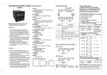
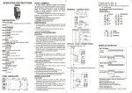
RATE OR TOTAL DISPLAY MODE:
The RC102C toggles between RATE display and
TOTAL display at the momentary press of R/T ( ) key
.In rate mode RATE LED glows & in totaliser mode
TOTAL LED glows.
4
6
COM (GND)
Reset input
5-6
Short to Filter input noise
Short to enter configuration
6-7
RATE
9 - 10
L- N
Live - Neutral
press (
)
key momentary
INPUT CONNECTIONS:
PNP proximity sensor
PNP
O/P
1
CNT
RESETTING THE RC102C
4
5
6
+12V
RST
COM
3
2
A. By front key: Press R/T
Short 2 & 3
NOTE: For PNP sensor input, short terminals 2 & 3.
NPN proximity sensor
1
GND
V+
4
5
6
+12V
RST
COM
3
2
CNT
key continuously for 3
sec. The totaliser resets to zero and starts counting
again, and the display shows the rate or total as per
selection.
B. Remote reset:
NPN
O/P
TOTAL
GND
V+
The RC102C can be reset from a remote push
button as shown in the figure below:
Reset by potential free switch
Short 1 & 2
NOTE: For NPN sensor input, short terminals 1 & 2.
Potential free contact
1
2
CNT
3
4
5
6
+12V
RST
COM
INITIALISATION:
1
2
3
CNT
4
5
6
+12V
RST
COM
Short 2 & 3
NOTE: Short terminals 2 & 3.
Sensor color codes:Red = +12V, Green = CNT, Black = GND;
Brown = +12V, Black = CNT, Blue = GND.
NOTE:
In some applications, the proximity sensors
may pick up high frequency noise form nearby
switching circuits like AC / DC drive, Due to
this the counter may show erroneous reading.
Short terminals 6-7 for RC102C as shown in
figure above, to filter out high frequency
spurious pulses by limiting the input frequency to
about 200Hz (1200 RPM).
Switch off the power. Short terminal no. 9 &10. Press
key at the time of turning the power on. The key
must continue to remain pressed for another 3 sec.
When this sequence is correctly performed, the unit
initialises and all parameters are set to factory
settings.
Scale factor changes to 1 (mantissa = 1.0000 &
exponent = 100=1), Resolution = 1, Maximum input
frequency = 2500 Hz.Totaliser resets to 0.
After initialisation unit will go into configuration
setting mode. To quit configuration setting mode:
1) Turn power off
2) Remove link between terminal nos 9 & 10
3) Turn power on.
Document name: Operating / 0809 / RC102C / ver3 OP191-V03 (Page 1 of 2)
CONFIGURATION SCHEME
To enter configuration short terminals 9 & 10
and turn the power on.
Configure the unit as per the instructions below.
1. To select scale factor mantissa
KEY PRESS
Scale factor
mantissa
DISPLAY
Set between
0.00001 to 9.99999
as described below:
2. Press R/T
key to select scale
factor exponent
Press
Press
Press
100 = 1
Press
Press
1) Turn power off.
2) Remove link between terminal no 9 & 10.
3) Turn power on.
TO READ SCALE FACTOR ,
RESOLUTION & SPEED
DISPLAY
NAME /
DESCRIPTION
PRG
Scale Factor
(Mantissa)
-3
PRG
Scale Factor
(Exponent)
-2
PRG
Totaliser Least
Count
PRG
Maximum Input
Speed
2
10 = 100
10 = 0.01
10-1 = 0.1
Least count = 1
Least count = 0.1
Least count = 0.01
Press
5. Press R/T
key to complete
setting, display will go to step 1
(scale factor mantissa setting).
To quit configuration:
KEY PRESS
R AT E
selec
TO TA L
PRG
R/T
RC102
Slow speed
(maximum 30 hz )
10 1 = 10
3. Press R/T
key to select
totaliser resolution
Totaliser
resolution
Fast speed
(maximum 2500 hz)
Press
(MOMENTARY)
10 = 0.001
Press
Max. input
frequency
DESCRIPTION
The blinking digit increments by 1 for every press
of the key & rolls over from 9 to 0. The blinking
digit shifts to next digit (right) for every press of
key. Using these keys user can set the required
value.
Scale factor
exponent
4. Press R/T
key to select max.
input frequency
NOTE: Maximum display time is 3 sec. If the key
is pressed again within 3 sec of previous key
press, display shows next parameter, otherwise
it shows rate or total as per selection.
TYPICAL APPLICATION:
Objective: To display: a. The total length of cord (in
meters) that has passed over the measuring
wheel
b. The delivery rate of cord (meters / minute).
Data available:
The proximity switch generates 1 pulse /
revolution of the measuring wheel. The diameter
of the wheel is 10cm.
Measuring
Wheel
Proximity
Switch
Calculations
Circumference of the wheel = 3.14285 x 0.1 =
0.314285m.
Therefore the length of rope delivered per
revolution is 0.314285m.
Since the proximity switch gives one pulse per
revolution, the display should increment by
0.314285 for every pulse. Therefore, scale factor
= 0.314285.
Set scale factor mantissa = 3.14285 & exponent =
10-1
The RC102C will show rate in meters / minute &
total in meters.
Example 2: If 60 PPR encoder is fitted instead of
proximity.
Length of rope delivered per revolution is
0.314285m.
Number of pulses per revolution = 60.
Length of rope delivered / pulse = 0.314285 / 60 =
0.005238m.
The display should increment by 0.005238 for
every pulse. Therefore, scale factor = 5.23800 x
10-3
Set scale factor mantissa = 5.23800 & exponent =
10-3 for the required display.
(Specifications subject to change as development
is a continuous process).
Selec Controls Pvt. Ltd., India.
(Formerly Selectron Process Controls Pvt. Ltd.)
Tel:91-22-28476443, Fax:91-22-28471733,
Website: www.selecindia.com
E- mail: [email protected].
Document name: Operating / 0809 / RC102C / ver3 OP191-V03 (Page 2 of 2)