1
PLS
PALASM Synthesis
PALASM Synthesis
Table of Contents
PALASM Synthesis
1. Introduction ______________________________________________________________________ 1
2. A simple example of PALASM file ____________________________________________________ 1
3. An example of State Machine ________________________________________________________ 4
4. PALASM elements ________________________________________________________________ 6
5. Boolean Design Strategies ___________________________________________________________ 8
5.1. Pin and Node __________________________________________________________________ 8
5.2. Polarity ______________________________________________________________________ 9
5.3. Three-State Output Buffers ______________________________________________________ 10
5.4. Controlling Clocks ____________________________________________________________ 10
5.5. Controlling Reset and Preset _____________________________________________________ 10
5.6. Vectors _____________________________________________________________________ 11
5.7. IF-THEN-ELSE Statement ______________________________________________________ 12
5.8. CASE statement ______________________________________________________________ 13
5.9. String Substitution_____________________________________________________________ 14
5.10. Substitution operator __________________________________________________________ 14
6. State Machine Design Strategies _____________________________________________________ 15
6.1. Initializing a State Machine______________________________________________________ 15
6.1.1. Using STARTUP_UP_______________________________________________________ 15
6.1.2. Using the .RSTF and .SETF functional equations _________________________________ 16
6.2. Clocking a State Machine _______________________________________________________ 16
6.2.1. Using CLKF statement ______________________________________________________ 16
6.2.2. Using .CLKF equations _____________________________________________________ 17
6.3. Assigning State Bits ___________________________________________________________ 17
6.3.1. Manual state-bit assignment __________________________________________________ 17
6.3.2. Automatic state-bit assignment________________________________________________ 18
6.4. Default Branches ______________________________________________________________ 18
6.4.1. Global defaults ____________________________________________________________ 18
6.4.2. Local defaults _____________________________________________________________ 18
6.5. Transition Equations ___________________________________________________________ 19
6.6. Output Equations______________________________________________________________ 19
6.7. Condition Equations ___________________________________________________________ 20
6.8. Choice of type of memory elements _______________________________________________ 20
7. PALASM Syntax Limitations _______________________________________________________ 21
8. Error Messages___________________________________________________________________ 22
9. Warning Messages ________________________________________________________________ 28
10. Other errors ____________________________________________________________________ 30
11. Menu _________________________________________________________________________ 31
12. On-Line Mode __________________________________________________________________ 32
PALASM Synthesis
PALASM Synthesis
PALASM Synthesis
PALASM Synthesis
PALASM Synthesis
1. Introduction
This section provides a general overview of how to use PALASM language in
order to generate source files using both Boolean equations and state machine
syntax. A PALASM file has a file extension of .PDS (PALASM Description
Specification) and is divided into several segments:
DECLARATION SEGMENT
EQUATIONS SEGMENT
STATE SEGMENT
SIMULATION
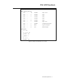
2. A simple example of PALASM file
All PDS files include a declaration segment and usually a simulation segment.
Depending upon the type of design description, the PDS file will contain an
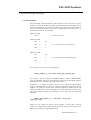
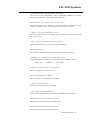
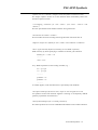
equations segment or/and a state segment. Figure 1 shows a simple PALASM
equation file for a FPGA design (upper case text designates PALASM key
words):
; Example of PALASM file
; Comment line, first character is ';'
CHIP example USER
; Design name and device type
clk a b c d r f g h
; Input/Output signals
EQUATIONS
f = a * /b
g := a * /(c + d)
; Combinatorial equation
; Registered output
g.CLKF = clk
; Clock signal specification
g.RSTF = /r
; Reset signal specification
h *= a + b
; Latched output
h.CLKF = clk
; Clock signal specification
Figure 1: Simple PALASM file
The lines above the keyword EQUATIONS are the declaration segment and the
following lines are the logic of the design expressed in Boolean equations.
The logical AND is indicated by an asterisk (*), the plus sign (+) indicates an OR
operation and the forward slash (/) indicates that the input is inverted.
The single equality character = indicates a combinatorial equation, for instance,
f in this example. The colon and equal characters together define a registered
PALASM Synthesis - 1
PALASM Synthesis
output, in this case a D-type flip-flop is assumed. The right side of g equation
represents the data input (D) of the flip-flop. The clock input, clk, for the flipflop is defined explicitly (since the device type is USER) with the equation
g.CLKF. An asynchronous register reset for g is specified with the equation
g.RSTF.
The *= characters , as shown in equation h, define a latched output. The data
input for the latch is the right side of the equation and the clock signal is
specified by the equation h.CLKF.
In this example the device name is USER, which means a generic device name
and normally the CHIP statement contains a real device name (PAL22V10,
MACH130, etc.). In this case, an optional placement of input/output signals may
be done on the device pins. The pin assignment list may be specified in two
modes: old syntax and new syntax. For the old syntax mode, the pin list contains
the names of the signals connected to package pins in numerical order of the
pins. A non connected pin is indicated by the "nc" (no-connect) signal name.
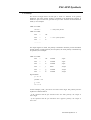
Figure 2 shows the input/output signal list of the preceding example, placed on a
PAL22V10 device.
; Example of PALASM file
CHIP example PAL22V10
clk a b c d r nc nc nc nc nc GND nc f g h nc nc nc nc nc nc nc VCC
EQUATIONS ......
Figure 2: Using a PLD device type: old syntax
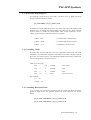
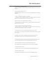
For the new syntax mode, the list of pins is specified with the PIN statements, as
shown in figure 3.
The new syntax representation of input/output signals also allows the
specification of combinatorial, registered or latched type of output signal. In
this case, it is no longer necessary to specify this type in the equation segment. If
the designer does not want to specify the placement of input/output signals, he
must use the '?' character in the place of pin number. For instance, the simple
example of PALASM file may be as shown in figure 4.
; Example of PALASM file
CHIP example PAL22V10
PIN
1
clk
; input, clock
PIN
2
a
; input
PIN
3
b
; input
PIN
4
c
; input
PIN
5
d
; input
PIN
6
r
; input, reset
PIN
14
f
; combinatorial output
PIN
15
g
; registered output
PIN
16
h
; latched output
..............................................
Figure 3: Using a PLD device type: new syntax
PALASM Synthesis - 2
PALASM Synthesis
; Example of PALASM file
CHIP example PAL22V10
PIN
?
clk
COMB
; input, clock
PIN
?
a
COMB
; input
PIN
?
b
COMB
; input
PIN
?
c
COMB
; input
PIN
?
d
COMB
; input
PIN
?
r
COMB
; input, reset
PIN
?
f
COMB
; combinatorial output
PIN
?
g
REG
; registered output
PIN
?
h
LAT
; latched output
EQUATIONS
f = a * /b
g = a * /(c + d)
g.CLKF = clk
g.RSTF = /r
h=a+b
h.CLKF = clk
Figure 4: Simple PALASM file: new syntax
PALASM Synthesis - 3
PALASM Synthesis
3. An example of State Machine
PALASM language can be used to describe the function of state machines: Mealy
and Moore machines. Outputs in a Moore machine are dependent only on the
present state. A Mealy machine is one where the outputs are a function of the
present state and the inputs.
The state machine description begins with the keyword STATE on a new line,
followed by the keyword MOORE_MACHINE or MEALY_MACHINE, which
defines the machine type (the default is Mealy). It is not possible to define both
types in the same design file.
There are four types of state machine equations:
- state assignment equations (optional) : specify the bit code to be assigned for
each state name used in the design;
- transition equations (required) : specify for each state what the next state will
be under various conditions;
- output equations (optional) : specify the output of the state machine (when the
state bits themselves are the outputs, then no output equations are required);
- condition equations (normally required) : specify a condition expression for
each state transition.
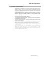
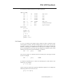
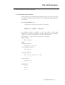
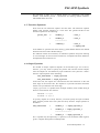
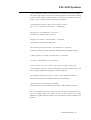
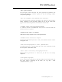
Figure 5 shows the design for a Moore machine. All types of equations are
present. There are four states (s0, s1, s2, s3), and two outputs (x, y). The
assignment equations are specified by the user, and the condition equations are,
in this case, reduced to single variables.
PALASM Synthesis - 4
PALASM Synthesis
CHIP test USER
clk a b c q0 q1 x /y
STATE
MOORE_MACHINE
; state assignment equations
S0 = /q0 * /q1
S1 = q0 * /q1
S2 = /q0 * q1
S3 = q0 * q1
; transition equations
S0 := up -> S1 + down -> S3 +-> S0
S1 := up -> S2 + down -> S0 +-> S1
S2 := up -> S3 + down -> S1 +-> S2
S3 := up -> S0 + down -> S2 +-> S3
;output equations
S0.OUTF = x * /y
S2.OUTF = x * y
S3.OUTF = /x * /y
CONDITIONS
up = a
down = b
EQUATIONS
q0.RSTF = /c
q1.RSTF = /c
Figure 5: PALASM file for Moore State Machine
The state assignment equations specify the code assigned for each state, using
local variables q0 and q1: S0 = (00) , S1 = (01), S2 = (10), S3 = (11).
A state change from S0 to S1 occurs when "up" is asserted, but if "down" is
asserted the change is to state S3, and if neither is asserted - the state S0 does not
change. The operator := indicates that the transitions happen only on clock
edges. The transitions for the other states are similarly defined.
Outputs x and y in this case are combinatorial, but may also be sequential using
the := operator. Output equations have always the ".OUTF" specification as a
suffix for the state name. Combinatorial outputs will transition on the next clock
edge, while sequential outputs will transition one cycle after the next clock edge.
For instance, when the machine will be in state S2, the output variables x and y
will be asserted.
The EQUATIONS segment contains only two equations for the initial reset of
state machine. In this case, the beginning state will be the state S0 (00).
The clock input to the state registers is not specified and, by default, this will be
the first signal from the input/output variable list (pin 1 is generally the clock
entry for a large number of PLDs). Other clock input may be specified with the
statement CLKF = clock_name.
PALASM Synthesis - 5
PALASM Synthesis
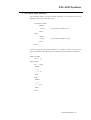
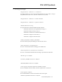
4. PALASM elements
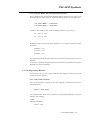
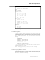
Table 1 identifies all elements available for use in each segment of a PDS file.
Table 1: PALASM elements
DECLARATION SEGMENT
AUTHOR
GROUP
REVISION
CHIP
LATCHED
SIGNATURE
COMBINATORIAL
NODE
STRING
COMPANY
PATTERN
TITLE
DATE
PIN
VECTOR
GROUP
REGISTERED
EQUATIONS SEGMENT
BOOLEAN EQUATION
EQUATION
IF-THEN-ELSE
EXPRESSION
J EQUATION
.T2 EQUATION
CASE
.K EQUATION
.TRST
.CLKF
.T1
.PRLD
EQUATIONS
.R EQUATION
FUNCTIONAL EQUATION
.S EQUATION
GND
.SETF
VCC
VECTOR
STATE SEGMENT
EXPRESSION
MASTER_RESET
STATE
CLKF
MEALY_MACHINE
STATE ASSIGNMENT
CONDITIONS
MOORE_MACHINE
STATE EQUATIONS
DEFAULT_BRANCH
.OUTF
STATE TRANSITIONS
DEFAULT_OUTPUT
OUTPUT_HOLD
VECTOR
LOCAL DEFAULT
START_UP
SIMULATION SEGMENT
EXPRESSION
PRELOAD
TRACE_ON
CHECK
PRLDF
VECTOR
CLOCKF
SETF
WHILE-DO
FOR-TO-DO
SIMULATION
IF-THEN-ELSE
TRACE_OFF
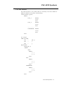
All the segments accept comment lines, which begin with the ";" character. The
most used PALASM operators are shown in table 2.
PALASM Synthesis - 6
PALASM Synthesis
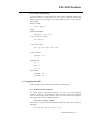
Table 2: Commonly used PALASM operators
Operator
Definition
/
NOT
*
AND
+
OR
:+:
XOR
:*:
XNOR
=
Combinatorial equation
:=
Registered equation
*=
Latched operation
->
State transition
+->
Local default
{}
Substitute
#b
Binary radix
#d
Decimal radix
#o
Octal radix
#h
Hexadecimal radix
''
String delimiters
[]
Vector element
()
Expression definition
..
Range for vector definition
PALASM Synthesis - 7
PALASM Synthesis
5. Boolean Design Strategies
5.1. Pin and Node
All input/output signal declarations, which appear in the declaration segment,
are known as PIN declarations and they are associated with input/output pins of
the device. Declaration of a PIN may be done in the old syntax format, which is
a list of input/output signals in the order of input/output pins of the device, or
with the PIN statement. For example:
CHIP test USER
clk a b ...
<-- old syntax format
CHIP test USER
PIN
1
clk
PIN
2
a
PIN
3
b
<-- new syntax format with placed pins
.................
CHIP test USER
PIN
?
clk
PIN
?
a
PIN
?
b
<-- new syntax format with floating pins
.................
The syntax for PIN statement is the following:
PIN pin_number_or_? pin_name storage_type [pairing_info]
"pin_storage" may be COMB or COMBINATORIAL, REG or REGISTERED,
LAT or LATCHED. Pairing is the possibility to pair input and output registers
with I/O pins so as to provide registered or latched I/O.
Sometimes, it is useful to define internal nodes within the EQUATIONS
segment. Internal nodes are not used as output, but provide clarity when writing
equations. To create an internal node, write the equation as normal, but do not
include the node name in the input/output list of the declaration segment. The
new syntax format permits the declaration of the node with the following
statement:
NODE node_number_or_?
[output_pair_info]
node_name
storage_type
Nodes are very useful for devices, which support "buried nodes". Internal
equations corresponding to nodes will be placed on internal cells of the device,
making it possible to fit large designs better.
PALASM Synthesis - 8
PALASM Synthesis
5.2. Polarity
The active low/high nature of each pin or node is a function of its polarity
definition. For input signals, polarity is defined in the declaration segment: to
define the pin as active low, precede the pin name with the forward character
slash (/). For example:
CHIP test USER
/clk a /b ...
<-- old syntax format
CHIP test USER
PIN
?
/clk
PIN
?
a
PIN
?
/b
<-- new syntax format
.................
For output signals or nodes, the polarity is defined in both the pin list statements
and the output or node equation (for old syntax, the node polarity is defined only
in equation). For example:
CHIP test USER
PIN
?
/clk
COMB
; input
PIN
?
a
COMB
; input
PIN
?
/b
COMB
; input
PIN
?
f
REG
; output
PIN
?
/g
COMB
; output
PIN
?
/h
COMB
; output
EQUATIONS
/f = a + /b
f.CLKF = clk
g = a *b
/h = /a + b
In this example, f and g are active low and h active high. The polarity rule for
equations is defined below:
- if the equation and the pin statement have the same polarity, the output is
active high;
- if the equation and the pin statement have opposite polarity, the output is
active low.
PALASM Synthesis - 9
PALASM Synthesis
5.3. Three-State Output Buffers
To explicitly control the three-state buffer, you have to use a .TRST functional
equation with the following syntax:
pin_name.TRST = pin_or_product_term
To enable the output buffer at all times, put in the right side of the equation the
keyword VCC. To disable the output buffer at all times, set the .TRST equation
equal to GND. To enable the output buffer under certain conditions, set the
.TRST equation equal to a Boolean equation. Example:
f.TRST = VCC
; unconditionally enabled output
g.TRST = GND
; unconditionally disabled output
h.TRST = a * /b
; conditionally enabled output
5.4. Controlling Clocks
To control the clock of a flip-flop, you have to define the clock signal with a pin
statement in the declaration segment of the PDS file and then use this signal in
the .CLKF functional equation. The following example shows how to define and
use a clock signal for a PAL22V10 device:
CHIP test PAL22V10
PIN
1
clk
COMB
; input, clock
PIN
2
a
COMB
; input
PIN
3
b
COMB
; input
PIN
14
f
REG
; registered output
EQUATIONS
f = a + /b
f.CLKF = clk
5.5. Controlling Reset and Preset
The reset and preset signals are controlled with the .RSTF and .SETF functional
equations respectively. The general formats for these equations are shown
below:
pin_or_node_name.RSTF = pin_or_product_term
pin_or_node_name.SETF = pin_or_product_term
PALASM Synthesis - 10
PALASM Synthesis
The following example shows the use of these equations:
CHIP test USER
PIN
1
clk
COMB
; input, clock
PIN
2
a
COMB
; input
PIN
3
b
COMB
; input
PIN
4
c
COMB
; input
PIN
6
reset
COMB
; input, reset
PIN
14
f
REG
; combinatorial output
PIN
15
g
REG
; registered output
EQUATIONS
f = a + /b
f.CLKF = clk
f.RSTF = reset
g = /a * b
g.CLKF = clk
g.SETF = a * b * c
5.6. Vectors
A vector is a specific set of signals (inputs, outputs or nodes) in which the order
of the signals is constant. The most common type of vector is the range of pins
or nodes. A range is a set of pins or nodes that have the same root name and
members of the range are differentiated by subscript. For example, in the range
f[1..4], the members are: f[1], f[2], f[3], f[4]. Ranges are declared in pin or node
statement and referenced in other statements, for instance:
PIN
2..5
f[1..4]
COMB
You can use a single '?' to float the location of all the pins in the range as shown
in the next example:
PIN
?
f[1..4]
COMB
To reference individual pins or nodes use subscribed pin or node names in the
format f[n]. For example:
g := a * /b + f[2]
Vectors cannot be used on the right side of Boolean equations. For example the
following equation will result in a error:
f[1..4] = a * vec[0..3]
PALASM Synthesis - 11
PALASM Synthesis
5.7. IF-THEN-ELSE Statement
This statement allows to express logical operations to be expressed in natural
language. The syntax is the following:
IF condition THEN
BEGIN
actions
; performed if condition is true
END
ELSE
BEGIN
actions
; performed if condition is false
END
END
If you do not specify the ELSE condition, it is treated as a don't care, when the
logic is generated. The following is an example of using if-then-else statement:
CHIP test USER
clk a b c f g
EQUATIONS
IF c = 1 Then
BEGIN
f=0
g=a*b
END
ELSE
BEGIN
f=1
g = /a * /b
END
END
PALASM Synthesis - 12
PALASM Synthesis
5.8. CASE statement
The CASE statement is very useful, when it is necessary to test for a number of
different conditions. The syntax is the following:
CASE (condition_signals)
BEGIN
Value_1:
BEGIN
action
END
Value_2:
BEGIN
action
END
.......................
OTHERWISE:
BEGIN
Action
END
END
For example:
CHIP test USER
PIN
?
a[0..7]
PIN
?
f
PIN
?
g
EQUATIONS
CASE (a[0..7])
BEGIN
#h0F :
BEGIN
f=1
g=0
END
#h1F :
BEGIN
f=1
g=1
END
OTHERWISE:
BEGIN
f=0
g=0
END
END
PALASM Synthesis - 13
PALASM Synthesis
5.9. String Substitution
The STRING statement allows you to assign a string name to a character string
and, the use the string name anywhere in the reminder of the design file, instead
of repeating the character string. The palasm interpreter substitutes the character
string for the string name during processing. The syntax of the STRING
statement is the following:
STRING string_name 'expression'
Include the STRING statement after the PIN and NODE statements and before
the EQUATIONS and STATE statements. An example of the use of string
substitution is shown below:
CHIP test USER
a b c d x y out1 out2
STRING st 'a * (b + c + d)'
EQUATIONS
out1 = st + /x + y
out2 = st + x + /y
Finally, we have the following equations:
out1 = a * (b + c + d) + /x + y
out2 = a * (b + c + d) + x + /y
5.10. Substitution operator
The substitution operator is another shortcut in the use of expression
substitution. An example of the use of substitution operator is shown below:
CHIP test USER
a b c out1 out2 out3
EQUATIONS
out1 = a + b + c
out2 = {out1}
out3 = /({out1})
Finally, we have the following equations:
out1 = a + b + c
out2 = a + b + c
out3 = /a * /b * /c
PALASM Synthesis - 14
PALASM Synthesis
6. State Machine Design Strategies
6.1. Initializing a State Machine
A state machine can be initialized either using the START_UP statement or using
the .RSTF and .SETF functional equations on the flip-flops, which define the
state machine:
6.1.1. Using STARTUP_UP
The following is the syntax for START_UP statement:
START_UP := condition -> state_name
This statement forces the machine to state "state_name", when signal
"condition" is asserted. "Condition" must be defined in the CONDITION
equation section of the state machine, even if this is an input entry.
The designation := makes the reset synchronous. For example:
CHIP test USER
clk a b c q0 q1 x /y
STATE
MOORE_MACHINE
START_UP := reset -> S0
; state assignment equations
S0 = /q0 * /q1
..........................
; transition equations
S0 := up -> S1 + down -> S3 +-> S0
...........................
;output equations
S0.OUTF = x * /y
..........................
CONDITIONS
up = a
down = b
reset = /c
PALASM Synthesis - 15
PALASM Synthesis
6.1.2. Using the .RSTF and .SETF functional equations
This is shown in the previous PALASM description, where the reset state is S0
with the code (00). The syntax for .RSTF and .SETF equations is the following:
<var_name>.RSTF = <expression>
<var_name>.SETF = <expression>
Assume a state machine with 3 state encoding variables: q0, q1 and q2.
S0 = /q0 * /q1 * /q2
S1 = /q0 * q1 * /q2
....................
Resetting to state S1 with code (010), when the "reset" signal is asserted, is done
as follows:
q0.RSTF = reset
q1.SETF = reset
q2.RSTF = reset
The .RSTF and .SETF equations must be placed in the EQUATIONS segment of
PDS file.
If no reset is specified using the two above constructs, the internal state machine
flip-flops will not be initialized.
6.2. Clocking a State Machine
There are two ways to use a clock other than the default: CLKF statement and
.CLKF functional equation:
6.2.1. Using CLKF statement
This clock statement is placed in the state segment of PDS file and has the
following syntax:
CLKF = clock_signal
The specified clock signal will be used for clocking all the flip-flops in the state
machine. For example:
STATE
MEALY_MACHINE
CLKF = clock
................
PALASM Synthesis - 16
PALASM Synthesis
6.2.2. Using .CLKF equations
To use this method, you must declare the state registers, manually assigning the
state bits, and write a .CLKF equation for each register in the state machine. The
.CLKF equations must be placed in the EQUATIONS segment of the PDS file.
For Example:
CHIP test USER
clk a b c q0 q1 x /y
STATE
MOORE_MACHINE
START_UP := reset -> S0
; state assignment equations
S0 = /q0 * /q1
................
; transition equations
S0 := up -> S1 + down -> S3 +-> S0
................
;output equations
S0.OUTF = x * /y
................
CONDITIONS
up = a
down = b
reset = /c
EQUATIONS
q0.CLKF = clk
q1.CLKF = clk
6.3. Assigning State Bits
State assignment can be done either manually or automatically.
6.3.1. Manual state-bit assignment
To control state-bit assignment manually, you must use state assignment
equations. To do this, you must define in the declaration segment of the PDS file
a pin or node for each of the state bits. Then, you write in the state segment a
state assignment equation in Boolean format:
state_name = boolean_equation
For example, in the previous PALASM description, the states are encoding as
following:
S0 = (00), S1 = (01), S2 = (10), S3 = (11).
PALASM Synthesis - 17
PALASM Synthesis
6.3.2. Automatic state-bit assignment
Different automatic encoding algorithms can be used with the help of the
«encoding option" of the menu mode or the -c option of the command mode:
. ONE for one-hot encoding; this technique uses one register for each state, i.e.
for each state one of the n internal variable has the value 1, where n is the
number of states. This option is only available for D flip-flops and is
recommended for speed optimization.
. OPT for compact encoding; this technique uses the minimal number of memory
elements and tends to minimize both the literal count in the next state and
output functions. It is recommended for area optimization.
. GRAY for Gray encoding; recommended for controller exhibiting long path
without branching
. JOHN for Johnson encoding; recommended for controller exhibiting long path
without branching
. SEQ for sequential encoding
. RAN for random encoding
6.4. Default Branches
Default branches are used to define the next transition state, when the inputs fail
to match any of the transition conditions, defined for the present state. Two types
of default branches may be specified: global defaults and local defaults. Global
defaults specify the default branch for all states, except those for which local
defaults are defined. Local defaults specify the default branch for only one state.
Both global and local defaults may be included in the same design, but local
defaults will override global defaults.
6.4.1. Global defaults
The global default statement must appear after the machine-type definition and
can specify the default branch in three ways:
DEFAULT_BRANCH HOLD_STATE : this statement causes the state machine to
remain in the same state, if the inputs do not match any of the defined condition
transitions for that state.
DEFAULT_BRANCH state_name : this statement causes the state machine to
branch to the specified state, if the inputs do not match any of the defined
condition transitions for that state.
DEFAULT_BRANCH NEXT_STATE : this statement causes the state machine to
branch to the next state, if the inputs do not match any of the defined condition
transitions for that state. The next state is defined as the state whose transition
equations follow the transition equation for the present state. Obviously, there is
no next-state branch possible for the state, whose transition equations appear
last.
6.4.2. Local defaults
Local defaults always specify a branch to a specific state and can be used alone
or in combination with global defaults. There is no specific statement for local
defaults. These appear as the last transition in the transition equation, using the
special symbol +->. For example:
S0 := condition1 -> S1 + condition2 -> S2 +-> S3
PALASM Synthesis - 18
PALASM Synthesis
The transition to state S3 is a default branch. In combination with global
defaults, local defaults provide a mechanism for defining defaults branches,
which differ from the norm.
6.5. Transition Equations
There must be one transition equation for each state. The transition equation
defines each possible transition to a next state. The general format for the
transition equation is the following:
present_state
:=
condition_1
-> state_1
+
condition_2
-> state_2
..........................
+
condition_n
-> state_n
+-> default_state
Local default is optional and when missing, global default defines the default
branch for the entire state machine design.
The software checks the consistency of transition equations and prints warning
or error messages for non-exclusive transitions, incomplete transition definition,
incompatible state transitions etc.
6.6. Output Equations
The format of output equations depends on the machine type. For a Moore,
machine, you only need to specify the present state and the desired outputs,
since the outputs are not affected by input conditions. The syntax for a Moore
machine output equation is the following:
state_name.OUTF = output_expression
state_name.OUTF := output_expression
In the first case, the outputs are combinatorial and will transition on the next
clock edge. In the second case, the outputs are sequential and their transitions
will be one cycle after the next clock edge.
"output_expression" is a product term of output variables, each variable being in
direct or inverted form. For instance:
S0.OUTF = x * /y * z
S1.OUTF = /x * /y * /z
To specify outputs for a Mealy machine you must specify the input condition
along with the present state. The syntax for Mealy machine output equations is
as follows:
state_name.OUTF
=
condition_1
+
-> output_expression_1
condition_2 -> output_expression_2
....................................
+
condition_n -> output_expression_n
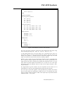
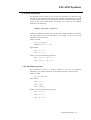
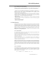
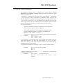
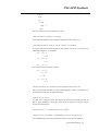
The = operator may be replaced by := operator, as for the Moore FSM. Figure 6
gives a complete description of a Mealy FSM.
PALASM Synthesis - 19
PALASM Synthesis
CHIP stat USER
/clk sensor enable red yellow green
STATE
MEALY_MACHINE
; transition equations
stop := car -> go +-> stop
go := car -> go2 +-> stop
go2 := car -> slow +-> stop
slow := VCC -> stop
; output equations
stop.OUTF = en -> red
go.OUTF = en -> red +-> green
go2.OUTF = en -> red +-> green
slow.OUTF = en -> red +-> yellow
CONDITIONS
car = sensor
en = enable
Figure 6: PALASM file for a Mealy State Machine
6.7. Condition Equations
A condition is a logical name for a set of inputs, which control a transition. The
conditions equations appear in the condition section of the STATE segment and
are preceded by the keyword CONDITIONS. The condition section must appear
after all STATE segment equations. The syntax for condition section is the
following:
CONDITIONS
condition_1 = Boolean_expression
condition_2 = Boolean_expression
................................
condition_n = Boolean_expression
If two conditions evaluate true at the same time, the software issues an
overlapping condition error message:
Error : Overlapping transitions for state Sm (next states : Sn and Sp)
6.8. Choice of type of memory elements
The type of storage elements is specified with the help of the "flip-flop type"
option of the menu mode or the -ff option of the command mode. Accepted
values are D, T, JK. Default is D flip-flop.
PALASM Synthesis - 20
PALASM Synthesis
7. PALASM Syntax Limitations
The supported PALASM syntax is defined in the AMD reference manual
(PALASM 4 user's manual - February 1991). The following limitations apply
for this PALASM syntax:
- valid names : all names must start with a letter or the character '_'. The format
is case insensitive: words constructed with identical alpha characters are
identical, regardless of whether the individual characters are upper or lower case;
- state machine specification : the specification of the different sections in the
STATE segment must obey the following rule: the transition equation section
must be immediately followed by the output equation section (if any);
- not supported features :
. Recursive definition of strings for substitution are not supported
. The .T1 and .T2 equations are not supported
. The following statements are not supported: MASTER_RESET,
OUTPUT_ENABLE, DEFAULT_OUTPUT, MINIMIZE_ON,
MINIMIZE_OFF, POWER_UP (see 6.1.1.)
()
. negation of a substitute operation must be enclosed between parenthesis
Example:
out1 = a + b + c
out2 = /({out1}); right
out2 = /{out1}; wrong
- reserved names : the PALASM parser uses internally some suffixes after the
signal names defined in the PDS file. These suffixes are: _OUT, _IN, TRST,
TRST_OUT, TRST_IN, TRST_PAD. Using these suffixes within signal names in
the PDS file may result in conflicts.
- assignment of constants for vectors by #b, #h or #o may not work properly.
Example:
d[1..2] = #b01 must be expressed
d[1] = 0
d[2] = 1
- complex Boolean expressions with *, +, :+:, :*: operators are not supported in
IF-THEN-ELSE conditions.
Example:
if (a * b) then ... : produces syntax error
if (a) then ... / if (a = 1) then ... / if (a = 0) then ... : works
properly
PALASM Synthesis - 21
PALASM Synthesis
8. Error Messages
• CHIP statement is not defined
You must define the CHIP statement. The syntax is:
CHIP <design_name> <device_name>
• Chip name specified in CHIP statement is unknown
The device name defined in CHIP statement must be a real device name, which
is listed in the user's manual, or a generic device: GENERIC, GENERIC_1CLK,
GENERIC_2CLK, and USER.
• Illegal extension <ExtensionName> at <Text>
Typical extension names are .CLKF, .RSTF, .SETF and .TRST
• Error in STRING definition
The STRING definition is not surrounded by single quotes (').
• Redefinition of <VariableName>
The specified variable appears more than once in the variable list.
• Undefined variable <VariableName> in group statement
The GROUP statement contains an undeclared variable.
• Illegal variable type <VariableType> in group statement
The variables specified in a GROUP statement must be signals (pin or internal
node).
• Illegal variable type <VariableType> in condition list
Variables within CONDITIONS section must be signals (pin or node).
• Undefined variable <VariableName>
A variable is found in the expressions, but is not defined anywhere in the
PALASM file.
• <Name> is not a pin or a node
The statement expected a signal name (pin or internal node), but something else
was given.
PALASM Synthesis - 22
PALASM Synthesis
• Substituted variable <VariableName> has no value
The user tries to do a substitution, but the substituted variable has not been
defined or the definition is below the current statement.
• Illegal variable type <VariableType> in expression
The type of variable is not legal for its use in expression. For instance, a state
variable is used as a vector, or a condition variable is used as a signal.
• <Name> is used, but not defined as a vector
The user specifies an index, for instance A[1], for a variable A, which is declared
but not as a vector.
• Value <value> is out of bounds for <VectorName>
The specified index is not in the range of vector definition.
• Illegal machine type
The supported state machines are Mealy machine and Moore machine.
• POWER_UP is not supported in START_UP statement
To initialize the state machine in a certain state, use the following syntax:
START_UP := <condition> -> <initial_state>
• START_UP.OUTF statement is not supported
This is not supported in current release.
• START_UP statement is redefined
You can only have one START_UP statement.
• <Name> is not a state name
The state name is used in the wrong place.
• Clock signal has multiple definitions
CLKF statement is specified more than once with different clock signals.
• DEFAULT_OUTPUT statement is redeclared
DEFAULT_OUTPUT can only be declared once.
• OUTPUT_HOLD statement is redeclared
OUTPUT_HOLD can only be declared once.
PALASM Synthesis - 23
PALASM Synthesis
• Illegal OUTPUT_ENABLE statement
OUTPUT_ENABLE is declared and also MASTER_RESET: they are mutually
exclusive.
• Illegal MASTER_RESET statement
MASTER_RESET is declared and also OUTPUT_ENABLE: they are mutually
exclusive.
• <Name> is used but not defined as a condition
A variable is used in transition equations (or output equations for Mealy
machines) and is already declared as a signal (pin or node).
• Output equation is not valid for MEALY machines
To specify outputs for a Mealy machine, you must specify the input conditions
along with the present state.
• Output equation is not valid for MOORE machines
To specify outputs for a Moore machine, you need to specify only the present
state and the desired outputs, without any conditions.
• Variable type for <Name> in output expression must be pin or node
The variable type used within an state machine output equation must be a signal
(pin or node).
• Variable type for <Name> in condition expression must be pin or node
The condition expression can only contain signal names (pin, node).
• Variable type for <Name> in state assignment expression must be pin or node
The state assign expression can only contain signal names (pin, node).
• Place CONDITION section after Transition and Output sections
The CONDITION section must be the last section in the STATE segment.
• Undefined condition <Name>
A condition name is used, but not defined within the CONDITION section.
• Redefined condition <Name>
The condition name must appear only once in the CONDITION section.
PALASM Synthesis - 24
PALASM Synthesis
• State assignment section is wrongly placed or a variable is used as a condition
The state assign section must not be placed between the transaction equation
section and the output equation section. It must precede or follow these two
sections. Also, the signals are not supported as conditions.
• Combinatorial variable <Name> must not have extension
e.g. A = B + C; you can't do A.CLKF = .... Meaningless
• Equation for <VariableName> is not used
An equation is specified, but is not used.
• Equation for variable <VariableName> is redefined
An equation is specified more than once.
• Functional equation for variable <VariableName> is redefined
A .RSTF or .SETF or .CLKF equation is redefined for the specified variable.
• .TRST equation for variable <VariableName> is redefined
• Variable <VariableName> is not declared
• Code <Number> for state <Name> is previously used for another state
A code number used for a state has already been used for an other state. User
incorrectly specified state assignments or output equations.
• Incompatible transitions from state <Name> with condition <Condition>
The user specified the state machine with the wrong transitions.
• Invalid extension <Extention> for GLOBAL
Accepted extensions for GLOBAL keyword are: .CLKF, .RSTF and .SETF.
• Error in condition expression : value has more bits than the condition pin list
This error appears when the number of bits of case selectors (For CASE
statement) is greater than the number of bits generated by the case condition. For
instance:
PALASM Synthesis - 25
PALASM Synthesis
case (a)
begin
16 :
begin
b[0] =1
end
The case selectors in this example are: 0 and 1.
• State bit number <Number> is too large
The maximum number of bits actually accepted for state coding is 31.
• Transition from state <State1> to state <State2> is redefined
The origin state for transition equations must appear only once. For instance, the
following example is not accepted:
s0 := c1 -> s1
+-> s0
s1 := c2 -> s2
+-> s1
s0 := c3 -> s3
This example must be written like this:
s0 := c1 -> s1
+ c3 -> s3
+-> s0
s1 := c2 -> s2
+-> s1
• Header statements are not found, at least CHIP statement must exist
None of the header statements of PALASM language (TITLE, AUTHOR, etc)
are found and especially the CHIP statement.
• Syntax error at <Text>
A syntax error is detected at the specified string from the PALASM input file. It
may be that a parameter is missing, a keyword or an operator is wrong or cannot
be accepted in that place.
• Syntax error at ->, condition name is not specified
• Syntax error at <Condition>, CONDITION section is wrongly placed
The CONDITION section must be the last section in the STATE segment.
PALASM Synthesis - 26
PALASM Synthesis
• Syntax error at <x.OUTF>, Output section must follow Transition section
The output equation section of a state machine must immediately follow the
transition equation section.
• Overlapping transitions for state <State> (next states: <State1> and
<State2>)
The user specified the state machine with the wrong transitions.
• Invalid state bit number <number>
The bit number for state encoding must be greater than 0 and less than 31.
• Different outputs are defined for state <Name> and condition <Condition>
• Reset signal is doubly defined (in START_UP and .RSTF equations)
FSM reset may by done specifying a condition in START_UP statement:
START_UP := cond -> s0
.............
cond = reset
or by .RSTF equations for state coding variables, e.g. :
s0 = /q1 * /q2
s1 = q1 * /q2
..............
q1.RSTF = rst
q2.RSTF = rst
..............
A conflict appears, when the FSM reset is specified by both methods.
• Incomplete FSM specification in state, output or state assignment section
An equation section from STATE segment is missing or incompletely defined
(possibly a premature end of the file).
• End of PALASM input file is reached prematurely
The same equations do not exist in BEGIN-END blocks for the CASE statement.
PALASM Synthesis - 27
PALASM Synthesis
9. Warning Messages
• Illegal character <Character> in <Statement>
An illegal character is used in the specified statement. It may be that a string is
not printable and in this case, a PC file is used for Unix systems.
• Illegal character <Character> in author statement
• Illegal character <Character> in pattern statement
• SIGNATURE name too long
The specified name in SIGNATURE statement must be:
- maximum 8 characters, for alphanumeric strings, or
- maximum 64 bits for binary radix, or
- maximum 16 characters for hexadecimal radix, or
- maximum 21 digits for octal radix, or
- maximum 15 digits for decimal radix.
• FSM type defaulted to MEALY_MACHINE
The user did not specify the FSM type in the STATE section.
• State assignment is <AssignmentType>
The user is warned about the encoding type for FSM states.
• State assignments are specified by user (MANUAL)
The user is warned that the FSM state encoding is specified in the PDS file.
• Machine type is redefined
• OUTPUT_ENABLE statement is redefined
• MASTER_RESET statement is redefined
• Clock signal is undefined, defaulted to MASTER_CLOCK
This is the default clock for FSM's, when the signal clock is not found.
• Clock signal is redefined
The CLKF statement is used twice with the same clock signal.
• DEFAULT_BRANCH statement is redefined
PALASM Synthesis - 28
PALASM Synthesis
• Reset signal is undefined
No reset signal is found for FSM. The reset signal may be specified in the
START_UP statement or in .RSTF equations for the state encoding variables
(see preceding message).
• Reset state is undefined, will be defaulted to state <StateName>
The reset state may be specified in the START_UP statement or by the help of
.RSTF equations for state encoding variables. If not, the first state, which
appears in the transition equations, is considered as the reset state.
• Condition <Name> is not used in transition equations
A condition is found in CONDITIONS section, but it is not used within the
transition section. It is ignored.
• Outputs for state <Name> are redefined
More than one output equation exists for the specified state.
• GLOBAL extension <Extension> is redefined
Extensions for GLOBAL keyword are: .CLKF, .SETF, .RSTF and each one must
only appear once.
• FSM clock is not defined for device <Name>, defaulted to Pin 1
In the given device, it is not clear which pin is the "clock". Therefore, assume
the first signal to be the master clock.
• Device <Name> is not in library, clock signal placed on Pin 1
Believe that the given device is a PAL device, but that it is not currently
supported.
• Clock signal is not specified
This is the case when a placement is specified by the user (new PIN syntax) but
the clock signal is floating on the clock pin (e.g. PIN ? CLK
COMBINATORIAL ; input).
PALASM Synthesis - 29
PALASM Synthesis
• Storage type conflict in .OUTF equations
This message appears, when the user specifies more than one type operator for
FSM output equations. For example:
S0.OUTF = /X * /Y
S1.OUTF := /X * Y
This implies a storage type conflict for output variable X, COMBINATORIAL
from the first equation and REGISTERED from the second. The final storage
type is given by the first encountered type, in
this case COMBINATORIAL.
• Storage type conflict detected in .OUTF for: <Name1>, <Name2> ...The list of
output variables with storage type conflicts is printed (see preceding message).
• Storage type for <Name> is <storage_type>
This message is printed when a conflict is detected between FSM output
equations. The <storage_type> type is that which is finally retained.
10. Other errors
• Can not open .kis file
• Can not open .cst file
• Can not open <FileName> file
• Variable not found for Id = <IdNumber>
• Error in Connector List for variable <VariableName>
PALASM Synthesis - 30
PALASM Synthesis
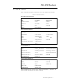
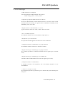
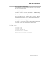
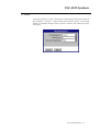
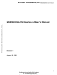
11. Menu
PALASM synthesis in PLS is obtained by selecting PALASM input format in
the Command -> Execute -> Input Format menu. Specific options to PALASM
format are available through "Source Options" window. The following display
will appear:
PALASM Synthesis - 31
PALASM Synthesis
12. On-Line Mode
To perform synthesis from PALASM format using the On line mode : place the
pointer on the "Command " menu in the menu bar of the main PLS window and
select "On Line Command". The "On line Command" window will appear.
The following parameter have to be defined in the command line :
• Encoding option
Value:
(-c)
SEQ for sequential encoding
ONE for one-hot encoding (recommended for speed optimization)
OPT for optimized encoding
GRAY for Gray encoding
JOHN for Johnson encoding
BEST for best encoding
RAN for random encoding
• Choice of type of the memory elements
Value:
D, T, JK or RS
Default:
The default value is D.
• Changing edge on the clock signal
Value:
RE or FE
Default:
Default value is RE.
(-ff)
(-ffsense)
PALASM Synthesis - 32