1
hp StorageWorks
data replication manager
hsg80 acs version 8.7p
scripting user guide
Part Number: EK-DRMSC-OA. E01
Fifth Edition (September 2002)
Product Version:
ACS Version 8.7P
DRM Scripting Kit Version 3.0
This user guide provides installation, configuration, and
operating procedures for running scripts with HP StorageWorks
Data Replication Manager. The scripts run on HP OpenVMS, HP
Tru64, IBM AIX, Microsoft Windows NT/2000, and Sun Solaris
hosts and handle eight specific failover, failback, and resumption
of operation situations.
© Hewlett-Packard Company, 2002. All rights reserved.
Hewlett-Packard Company makes no warranty of any kind with regard to this material,
including, but not limited to, the implied warranties of merchantability and fitness for a
particular purpose. Hewlett-Packard shall not be liable for errors contained herein or for
incidental or consequential damages in connection with the furnishing, performance, or use
of this material.
This document contains proprietary information, which is protected by copyright. No part of
this document may be photocopied, reproduced, or translated into another language
without the prior written consent of Hewlett-Packard. The information contained in this
document is subject to change without notice.
HP, Compaq, StorageWorks, SANworks, OpenVMS, and Tru64 are trademarks of
Hewlett-Packard Company in the U.S. and/or other countries.
Microsoft, Windows, and Windows NT are trademarks of Microsoft Corporation in the U.S.
and/or other countries.
UNIX is a trademark of The Open Group in the U.S. and/or other countries.
All other product names mentioned herein may be trademarks of their respective
companies.
Hewlett-Packard Company shall not be liable for technical or editorial errors or omissions
contained herein. The information is provided “as is” without warranty of any kind and is
subject to change without notice. The warranties for Hewlett-Packard Company products are
set forth in the express limited warranty statements accompanying such products. Nothing
herein should be construed as constituting an additional warranty.
Printed in the U.S.A.
Data Replication Manager HSG80 ACS Version 8.7P Scripting User Guide
Fifth Edition (September 2002)
Part Number: EK-DRMSC-OA. E01
Contents
About this Guide
Intended Audience . . . . . . . . . . . . . . . . . . . . . . . . . . . . . . . . . . . . . . . . . . . . . . . . . . . . . . . ix
Related Documentation . . . . . . . . . . . . . . . . . . . . . . . . . . . . . . . . . . . . . . . . . . . . . . . . . . . ix
Prerequisites . . . . . . . . . . . . . . . . . . . . . . . . . . . . . . . . . . . . . . . . . . . . . . . . . . . . . . . . . . . . x
Document Conventions . . . . . . . . . . . . . . . . . . . . . . . . . . . . . . . . . . . . . . . . . . . . . . . . . . . xi
Symbols in Text . . . . . . . . . . . . . . . . . . . . . . . . . . . . . . . . . . . . . . . . . . . . . . . . . . . . . . . . . xi
Symbols on Equipment . . . . . . . . . . . . . . . . . . . . . . . . . . . . . . . . . . . . . . . . . . . . . . . . . . xii
Rack Stability . . . . . . . . . . . . . . . . . . . . . . . . . . . . . . . . . . . . . . . . . . . . . . . . . . . . . . . . . . xiii
Getting Help . . . . . . . . . . . . . . . . . . . . . . . . . . . . . . . . . . . . . . . . . . . . . . . . . . . . . . . . . . . xiii
HP Technical Support . . . . . . . . . . . . . . . . . . . . . . . . . . . . . . . . . . . . . . . . . . . . . . . . xiii
HP Website . . . . . . . . . . . . . . . . . . . . . . . . . . . . . . . . . . . . . . . . . . . . . . . . . . . . . . . . xiv
HP Authorized Reseller . . . . . . . . . . . . . . . . . . . . . . . . . . . . . . . . . . . . . . . . . . . . . . . . . . xiv
1 DRM Scripting Overview
Introduction . . . . . . . . . . . . . . . . . . . . . . . . . . . . . . . . . . . . . . . . . . . . . . . . . . . . . . . . . . 1–1
Site Failover Basic Description . . . . . . . . . . . . . . . . . . . . . . . . . . . . . . . . . . . . . . . . . . . 1–2
Failback Procedure Choices. . . . . . . . . . . . . . . . . . . . . . . . . . . . . . . . . . . . . . . . . . . . . . 1–5
Summary of Failover/Failback Procedure Choices . . . . . . . . . . . . . . . . . . . . . . . . . . . . 1–6
Benefits of Scripts . . . . . . . . . . . . . . . . . . . . . . . . . . . . . . . . . . . . . . . . . . . . . . . . . . . . . 1–8
Components for Scripting . . . . . . . . . . . . . . . . . . . . . . . . . . . . . . . . . . . . . . . . . . . . . . . 1–8
HP DRM Scripting Kit . . . . . . . . . . . . . . . . . . . . . . . . . . . . . . . . . . . . . . . . . . . . . . 1–8
Perl Interpreter. . . . . . . . . . . . . . . . . . . . . . . . . . . . . . . . . . . . . . . . . . . . . . . . . . . . . 1–9
SANworks Command Scripter . . . . . . . . . . . . . . . . . . . . . . . . . . . . . . . . . . . . . . . . 1–9
How the Failover, Failback, and Resumption of Operation Scripts Work . . . . . . . . . . 1–9
Perl Scripts. . . . . . . . . . . . . . . . . . . . . . . . . . . . . . . . . . . . . . . . . . . . . . . . . . . . . . . . 1–9
User-Customized Script Support Files . . . . . . . . . . . . . . . . . . . . . . . . . . . . . . . . . . 1–9
Running a Script . . . . . . . . . . . . . . . . . . . . . . . . . . . . . . . . . . . . . . . . . . . . . . . . . . 1–10
The Scripting Process Flow . . . . . . . . . . . . . . . . . . . . . . . . . . . . . . . . . . . . . . . . . . . . . 1–12
Requirements . . . . . . . . . . . . . . . . . . . . . . . . . . . . . . . . . . . . . . . . . . . . . . . . . . . . . . . . 1–14
Platforms . . . . . . . . . . . . . . . . . . . . . . . . . . . . . . . . . . . . . . . . . . . . . . . . . . . . . . . . 1–14
Data Replication Manager HSG80 ACS Version 8.7P Scripting User Guide
iii
Contents
Hardware . . . . . . . . . . . . . . . . . . . . . . . . . . . . . . . . . . . . . . . . . . . . . . . . . . . . . . . . 1–15
Switch Zoning . . . . . . . . . . . . . . . . . . . . . . . . . . . . . . . . . . . . . . . . . . . . . . . . . . . . 1–16
Software . . . . . . . . . . . . . . . . . . . . . . . . . . . . . . . . . . . . . . . . . . . . . . . . . . . . . . . . . 1–16
2 Installation
Introduction. . . . . . . . . . . . . . . . . . . . . . . . . . . . . . . . . . . . . . . . . . . . . . . . . . . . . . . . . . .
HP DRM Scripting Kit . . . . . . . . . . . . . . . . . . . . . . . . . . . . . . . . . . . . . . . . . . . . . . . . . .
Installing the HP DRM Scripting Kit Files . . . . . . . . . . . . . . . . . . . . . . . . . . . . . . .
HP OpenVMS . . . . . . . . . . . . . . . . . . . . . . . . . . . . . . . . . . . . . . . . . . . . . . . . . .
HP Tru64 UNIX, IBM AIX, and Sun Solaris . . . . . . . . . . . . . . . . . . . . . . . . . .
Microsoft Windows NT/2000 . . . . . . . . . . . . . . . . . . . . . . . . . . . . . . . . . . . . . .
Perl Interpreter . . . . . . . . . . . . . . . . . . . . . . . . . . . . . . . . . . . . . . . . . . . . . . . . . . . . . . . .
HP OpenVMS . . . . . . . . . . . . . . . . . . . . . . . . . . . . . . . . . . . . . . . . . . . . . . . . . . . . .
Obtaining the OpenVMS Perl Interpreter . . . . . . . . . . . . . . . . . . . . . . . . . . . . .
Installing the OpenVMS Perl Interpreter. . . . . . . . . . . . . . . . . . . . . . . . . . . . . .
Microsoft Windows NT/2000 . . . . . . . . . . . . . . . . . . . . . . . . . . . . . . . . . . . . . . . . .
Obtaining the Windows Perl Interpreter (ActivePerl). . . . . . . . . . . . . . . . . . . .
Installing Windows ActivePerl . . . . . . . . . . . . . . . . . . . . . . . . . . . . . . . . . . . . .
Sun Solaris Versions 6 and 7 . . . . . . . . . . . . . . . . . . . . . . . . . . . . . . . . . . . . . . . . . .
Obtaining the Sun Solaris Versions 6 and 7 Perl Interpreter. . . . . . . . . . . . . . .
Installing the Sun Solaris Perl Interpreter . . . . . . . . . . . . . . . . . . . . . . . . . . . . .
SANworks Command Scripter . . . . . . . . . . . . . . . . . . . . . . . . . . . . . . . . . . . . . . . . . . . .
Obtaining SANworks Command Scripter . . . . . . . . . . . . . . . . . . . . . . . . . . . . . . . .
Installing SANworks Command Scripter. . . . . . . . . . . . . . . . . . . . . . . . . . . . . . . . .
HP OpenVMS . . . . . . . . . . . . . . . . . . . . . . . . . . . . . . . . . . . . . . . . . . . . . . . . . .
HP Tru64 UNIX . . . . . . . . . . . . . . . . . . . . . . . . . . . . . . . . . . . . . . . . . . . . . . . .
IBM AIX . . . . . . . . . . . . . . . . . . . . . . . . . . . . . . . . . . . . . . . . . . . . . . . . . . . . . .
Microsoft Windows NT/2000 . . . . . . . . . . . . . . . . . . . . . . . . . . . . . . . . . . . . . .
Sun Solaris. . . . . . . . . . . . . . . . . . . . . . . . . . . . . . . . . . . . . . . . . . . . . . . . . . . . .
2–1
2–1
2–1
2–2
2–2
2–3
2–4
2–4
2–4
2–4
2–4
2–4
2–4
2–5
2–5
2–5
2–5
2–5
2–5
2–6
2–7
2–7
2–8
2–9
3 CCL Setup
Introduction. . . . . . . . . . . . . . . . . . . . . . . . . . . . . . . . . . . . . . . . . . . . . . . . . . . . . . . . . . .
HP OpenVMS CCL and Job Queue Setup . . . . . . . . . . . . . . . . . . . . . . . . . . . . . . . . . . .
HP OpenVMS CCL Setup . . . . . . . . . . . . . . . . . . . . . . . . . . . . . . . . . . . . . . . . . . . .
HP OpenVMS Job Queue Setup . . . . . . . . . . . . . . . . . . . . . . . . . . . . . . . . . . . . . . .
HP Tru64 UNIX CCL Setup. . . . . . . . . . . . . . . . . . . . . . . . . . . . . . . . . . . . . . . . . . . . . .
IBM AIX CCL Setup . . . . . . . . . . . . . . . . . . . . . . . . . . . . . . . . . . . . . . . . . . . . . . . . . . .
Microsoft Windows NT/2000 CCL Setup . . . . . . . . . . . . . . . . . . . . . . . . . . . . . . . . . . .
iv
3–1
3–1
3–1
3–2
3–2
3–4
3–5
Data Replication Manager HSG80 ACS Version 8.7P Scripting User Guide
Contents
Sun Solaris CCL Setup. . . . . . . . . . . . . . . . . . . . . . . . . . . . . . . . . . . . . . . . . . . . . . . . . . 3–5
/kernel/drv/sd.conf. . . . . . . . . . . . . . . . . . . . . . . . . . . . . . . . . . . . . . . . . . . . . . . . . . 3–6
Entries to mda.conf and LdLite.conf . . . . . . . . . . . . . . . . . . . . . . . . . . . . . . . . . . . . 3–6
4 File Customization
Introduction . . . . . . . . . . . . . . . . . . . . . . . . . . . . . . . . . . . . . . . . . . . . . . . . . . . . . . . . . . 4–1
File Customization Steps . . . . . . . . . . . . . . . . . . . . . . . . . . . . . . . . . . . . . . . . . . . . . . . . 4–1
Configuration Generation File Creation. . . . . . . . . . . . . . . . . . . . . . . . . . . . . . . . . . . . . 4–3
HP OpenVMS . . . . . . . . . . . . . . . . . . . . . . . . . . . . . . . . . . . . . . . . . . . . . . . . . . . . . 4–3
HP Tru64 UNIX . . . . . . . . . . . . . . . . . . . . . . . . . . . . . . . . . . . . . . . . . . . . . . . . . . . 4–6
IBM AIX . . . . . . . . . . . . . . . . . . . . . . . . . . . . . . . . . . . . . . . . . . . . . . . . . . . . . . . . . 4–7
Microsoft Windows NT/2000 . . . . . . . . . . . . . . . . . . . . . . . . . . . . . . . . . . . . . . . . . 4–9
SCSI-2 Mode with No CCL Enabled . . . . . . . . . . . . . . . . . . . . . . . . . . . . . . . . 4–9
SCSI-3 Mode with CCLs . . . . . . . . . . . . . . . . . . . . . . . . . . . . . . . . . . . . . . . . 4–11
Sun Solaris. . . . . . . . . . . . . . . . . . . . . . . . . . . . . . . . . . . . . . . . . . . . . . . . . . . . . . . 4–13
Using the CCL . . . . . . . . . . . . . . . . . . . . . . . . . . . . . . . . . . . . . . . . . . . . . . . . 4–13
Using the Non-RCS LUN (No CCL) . . . . . . . . . . . . . . . . . . . . . . . . . . . . . . . 4–15
Running Configuration Generation Files . . . . . . . . . . . . . . . . . . . . . . . . . . . . . . . . . . . 4–17
HP OpenVMS . . . . . . . . . . . . . . . . . . . . . . . . . . . . . . . . . . . . . . . . . . . . . . . . . . . . 4–18
HP Tru64 UNIX, IBM AIX, and Sun Solaris . . . . . . . . . . . . . . . . . . . . . . . . . . . . 4–18
Microsoft Windows NT/2000 . . . . . . . . . . . . . . . . . . . . . . . . . . . . . . . . . . . . . . . . 4–18
Controller Configuration File Customization . . . . . . . . . . . . . . . . . . . . . . . . . . . . . . . 4–19
Target Controller Configuration File Customization . . . . . . . . . . . . . . . . . . . . . . 4–19
Association Set Section. . . . . . . . . . . . . . . . . . . . . . . . . . . . . . . . . . . . . . . . . . 4–19
Remote Copy Set Section . . . . . . . . . . . . . . . . . . . . . . . . . . . . . . . . . . . . . . . . 4–20
Connections Section . . . . . . . . . . . . . . . . . . . . . . . . . . . . . . . . . . . . . . . . . . . . 4–21
Maximum Read/Write Cached Transfer Size Section . . . . . . . . . . . . . . . . . . 4–22
Application Action List Customization . . . . . . . . . . . . . . . . . . . . . . . . . . . . . . . . . . . . 4–23
Customizing the Application Action List . . . . . . . . . . . . . . . . . . . . . . . . . . . . . . . 4–23
Example Customization of an Application Action List. . . . . . . . . . . . . . . . . . . . . 4–24
5 Scripting File Descriptions and Behaviors
Program File Descriptions . . . . . . . . . . . . . . . . . . . . . . . . . . . . . . . . . . . . . . . . . . . . . . .
Communicating Via Command Scripter . . . . . . . . . . . . . . . . . . . . . . . . . . . . . . . . . . . .
Verbose and Condensed Displays . . . . . . . . . . . . . . . . . . . . . . . . . . . . . . . . . . . . . . . . .
Terminating a Script . . . . . . . . . . . . . . . . . . . . . . . . . . . . . . . . . . . . . . . . . . . . . . . .
HP OpenVMS . . . . . . . . . . . . . . . . . . . . . . . . . . . . . . . . . . . . . . . . . . . . . . . . . .
HP Tru64 UNIX, IBM AIX, and Sun Solaris . . . . . . . . . . . . . . . . . . . . . . . . . .
Data Replication Manager HSG80 ACS Version 8.7P Scripting User Guide
5–1
5–2
5–3
5–5
5–5
5–6
v
Contents
Microsoft Windows NT/2000 . . . . . . . . . . . . . . . . . . . . . . . . . . . . . . . . . . . . . . 5–6
6 Unplanned Site Failover with Full Failback Procedure
Running the Unplanned Failover Program File Procedure. . . . . . . . . . . . . . . . . . . . . . .
Target Host Setup Procedure . . . . . . . . . . . . . . . . . . . . . . . . . . . . . . . . . . . . . . . . . . . . .
Running the Full Failback Program Files Procedure . . . . . . . . . . . . . . . . . . . . . . . . . . .
Initiator Site Cleanup Procedure. . . . . . . . . . . . . . . . . . . . . . . . . . . . . . . . . . . . . . . . . . .
6–1
6–2
6–5
6–7
7 Resumption of Operations After Unplanned Loss of Target Site
Procedure (Failsafe Mode)
Verification of Lost Connections Procedure . . . . . . . . . . . . . . . . . . . . . . . . . . . . . . . . .
Running the Resumption of Operations Program File Procedure . . . . . . . . . . . . . . . . .
Initiator Site Cleanup Procedure. . . . . . . . . . . . . . . . . . . . . . . . . . . . . . . . . . . . . . . . . . .
Running the Resumption of Operations Program File Procedure . . . . . . . . . . . . . . . . .
7–1
7–3
7–6
7–8
8 Resumption of Operations After Unplanned Loss of Target Site
Procedure (Normal Mode)
Verification of Lost Connections Procedure . . . . . . . . . . . . . . . . . . . . . . . . . . . . . . . . . 8–1
Running the Resumption of Operations Program Files Procedure. . . . . . . . . . . . . . . . . 8–2
9 Short Planned Site Failover with Fast Failback Procedure
Initiator Site Preparation Procedure . . . . . . . . . . . . . . . . . . . . . . . . . . . . . . . . . . . . . . . .
Running the Short Planned Failover Program File Procedure . . . . . . . . . . . . . . . . . . . .
Target Host Setup Procedure . . . . . . . . . . . . . . . . . . . . . . . . . . . . . . . . . . . . . . . . . . . . .
Running the Fast Failback Program Files Procedure . . . . . . . . . . . . . . . . . . . . . . . . . . .
Initiator Site Cleanup Procedure. . . . . . . . . . . . . . . . . . . . . . . . . . . . . . . . . . . . . . . . . . .
9–1
9–2
9–3
9–6
9–8
10 Extended Planned Site Failover with Full Failback Procedure
Initiator Site Preparation Procedure . . . . . . . . . . . . . . . . . . . . . . . . . . . . . . . . . . . . . . .
Running the Extended Planned Failover Program File Procedure . . . . . . . . . . . . . . . .
Target Host Setup Procedure . . . . . . . . . . . . . . . . . . . . . . . . . . . . . . . . . . . . . . . . . . . .
Running the Full Failback Program Files Procedure . . . . . . . . . . . . . . . . . . . . . . . . . .
Initiator Site Cleanup Procedure. . . . . . . . . . . . . . . . . . . . . . . . . . . . . . . . . . . . . . . . . .
10–1
10–4
10–5
10–7
10–9
11 Resumption of Replication After Extended Planned Loss of Target
Procedure (Failsafe Mode)
Running the Resumption of Replication Program File Procedure . . . . . . . . . . . . . . . . 11–1
Continuing the Resumption of Replication Program File Procedure . . . . . . . . . . . . . . 11–4
vi
Data Replication Manager HSG80 ACS Version 8.7P Scripting User Guide
Contents
12 Unplanned Site Failover with Failback to New Hardware Procedure
Running the Unplanned Failover Program File Procedure . . . . . . . . . . . . . . . . . . . . . 12–1
Target Host Setup Procedure . . . . . . . . . . . . . . . . . . . . . . . . . . . . . . . . . . . . . . . . . . . . 12–4
Initiator Site Preparation Procedure . . . . . . . . . . . . . . . . . . . . . . . . . . . . . . . . . . . . . . . 12–6
Running the New Hardware Failback Program Files Procedure . . . . . . . . . . . . . . . . 12–14
Initiator Site Cleanup Procedure . . . . . . . . . . . . . . . . . . . . . . . . . . . . . . . . . . . . . . . . 12–15
13 Planned Site Role Reversal Procedure
Initiator Site Preparation Procedure . . . . . . . . . . . . . . . . . . . . . . . . . . . . . . . . . . . . . . .
Running the Role Reversal Failover Program File Procedure . . . . . . . . . . . . . . . . . . .
Target Host Setup Procedure . . . . . . . . . . . . . . . . . . . . . . . . . . . . . . . . . . . . . . . . . . . .
Running the Role Reversal Failback Program File Procedure. . . . . . . . . . . . . . . . . . .
Initiator Site Cleanup Procedure . . . . . . . . . . . . . . . . . . . . . . . . . . . . . . . . . . . . . . . . .
13–1
13–3
13–4
13–7
13–8
A DRM Scripting Kit Files
B Sample Controller Configuration File
C Structure of the Application Action List
Default Application Action List. . . . . . . . . . . . . . . . . . . . . . . . . . . . . . . . . . . . . . . . . . .
Action Commands . . . . . . . . . . . . . . . . . . . . . . . . . . . . . . . . . . . . . . . . . . . . . . . . . . . . .
How the Perl Scripts Use the Application Action List . . . . . . . . . . . . . . . . . . . . . . . . .
hsgcontrol.pl . . . . . . . . . . . . . . . . . . . . . . . . . . . . . . . . . . . . . . . . . . . . . . . . . . . . . .
drmdispatch.pl . . . . . . . . . . . . . . . . . . . . . . . . . . . . . . . . . . . . . . . . . . . . . . . . . . . . .
C–1
C–5
C–6
C–6
C–7
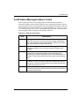
D Troubleshooting
Troubleshooting Recommendations. . . . . . . . . . . . . . . . . . . . . . . . . . . . . . . . . . . . . . . . D–1
Scripting Error Codes. . . . . . . . . . . . . . . . . . . . . . . . . . . . . . . . . . . . . . . . . . . . . . . . . . . D–2
Confirmation Message Instance Codes . . . . . . . . . . . . . . . . . . . . . . . . . . . . . . . . . . . . . D–9
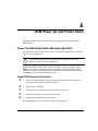
E DRM Power Up and Power Down
Power Up Data Replication Manager Systems . . . . . . . . . . . . . . . . . . . . . . . . . . . . . . .
Target Site Power Up Procedure . . . . . . . . . . . . . . . . . . . . . . . . . . . . . . . . . . . . . . .
Initiator Site Power Up Procedure. . . . . . . . . . . . . . . . . . . . . . . . . . . . . . . . . . . . . .
Power Down Data Replication Manager Systems . . . . . . . . . . . . . . . . . . . . . . . . . . . . .
Initiator Site Power Down Procedure . . . . . . . . . . . . . . . . . . . . . . . . . . . . . . . . . . .
Target Site Power Down Procedure . . . . . . . . . . . . . . . . . . . . . . . . . . . . . . . . . . . .
Data Replication Manager HSG80 ACS Version 8.7P Scripting User Guide
E–1
E–1
E–2
E–2
E–2
E–3
vii
Contents
Glossary
Index
Figures
1–1
1–2
1–3
4–1
4–2
4–3
4–4
5–1
5–2
6–1
Scripting information flow . . . . . . . . . . . . . . . . . . . . . . . . . . . . . . . . . . . . . . . 1–11
Script processing . . . . . . . . . . . . . . . . . . . . . . . . . . . . . . . . . . . . . . . . . . . . . . . 1–12
Data Replication Manager basic configuration . . . . . . . . . . . . . . . . . . . . . . . . 1–13
Generation file setup using a CCL . . . . . . . . . . . . . . . . . . . . . . . . . . . . . . . . . . 4–5
Generation file setup with a non-RCS LUN . . . . . . . . . . . . . . . . . . . . . . . . . . 4–10
Copying association set information . . . . . . . . . . . . . . . . . . . . . . . . . . . . . . . . 4–20
Copying remote copy set information . . . . . . . . . . . . . . . . . . . . . . . . . . . . . . . 4–21
Verbose status display . . . . . . . . . . . . . . . . . . . . . . . . . . . . . . . . . . . . . . . . . . . . 5–3
Condensed status display. . . . . . . . . . . . . . . . . . . . . . . . . . . . . . . . . . . . . . . . . . 5–4
Operation completion status result display . . . . . . . . . . . . . . . . . . . . . . . . . . . . 6–3
Tables
1
2
1–1
1–2
1–3
1–4
4–1
5–1
A–1
C–1
C–2
C–3
D–1
D–2
viii
Related Documentation . . . . . . . . . . . . . . . . . . . . . . . . . . . . . . . . . . . . . . . . . . . . ix
Document Conventions . . . . . . . . . . . . . . . . . . . . . . . . . . . . . . . . . . . . . . . . . . . . xi
Possible Failover Situations. . . . . . . . . . . . . . . . . . . . . . . . . . . . . . . . . . . . . . . . 1–3
Types of Failover and Failback . . . . . . . . . . . . . . . . . . . . . . . . . . . . . . . . . . . . . 1–5
Failover, Failback, and Resumption of Operations Procedure Choices . . . . . . 1–6
DRM Heterogeneous Operating Systems . . . . . . . . . . . . . . . . . . . . . . . . . . . . 1–15
Created or Customized Host Files . . . . . . . . . . . . . . . . . . . . . . . . . . . . . . . . . . . 4–2
RC File Location . . . . . . . . . . . . . . . . . . . . . . . . . . . . . . . . . . . . . . . . . . . . . . . . 5–4
Installed DRM Scripting Kit Files. . . . . . . . . . . . . . . . . . . . . . . . . . . . . . . . . . A–1
Structure of an Action Command . . . . . . . . . . . . . . . . . . . . . . . . . . . . . . . . . . C–5
Structure of the hsgcontrol.pl Script Command . . . . . . . . . . . . . . . . . . . . . . . C–6
Structure of the drmdispatch.pl Script Command . . . . . . . . . . . . . . . . . . . . . . C–7
Scripting Error Codes . . . . . . . . . . . . . . . . . . . . . . . . . . . . . . . . . . . . . . . . . . . D–2
Instance Code Legend . . . . . . . . . . . . . . . . . . . . . . . . . . . . . . . . . . . . . . . . . . . D–9
Data Replication Manager HSG80 ACS Version 8.7P Scripting User Guide
About this Guide
This user guide provides information to help you:
•
Acquire and install software required for using Data Replication Manager (DRM)
scripts.
•
Configure and customize files required for the scripts.
•
Run failover, failback, and resumption of operation scripts.
•
Contact technical support for additional assistance.
Intended Audience
This book is intended for use by DRM customers who are experienced with the
following:
•
Configuring a DRM environment to include zoning, write history logs, association
sets, and remote copy sets.
•
Running failover, failback, and resumption of operations with command line
interface (CLI) commands.
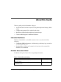
Related Documentation
In addition to this guide, HP provides corresponding information:
Table 1: Related Documentation
Document Title
Part Number
Compaq SANworks Command Scripter Version 1.0A
Release Notes
AA-RN6HB-TE
Compaq SANworks Command Scripter Version 1.0A
Installation Card
AE-RN6FB-TE
Data Replication Manager HSG80 ACS Version 8.7P Scripting User Guide
ix
About this Guide
Table 1: Related Documentation (Continued)
Document Title
Part Number
Compaq SANworks Command Scripter Version 1.0A
User Guide
AA-RN6EB-TE
HP StorageWorks Data Replication Manager HSG80 ACS
Version 8.7P Configuration Guide
AA-RPHZE-TE
HP StorageWorks Data Replication Manager HSG80 ACS
Version 8.7P Failover/Failback Procedures Guide
AA-RPJ0D-TE
HP StorageWorks HSG80 Array Controller ACS
Version 8.7 CLI Reference Guide
EK-G80CL-RA. B01
HP StorageWorks HSG80 Array Controller V8.7
Troubleshooting Reference Guide
EK-G80TR-SA. B01
Prerequisites
Before you run the DRM scripts, make sure you consider the items below.
x
•
This manual assumes a DRM configuration is in place before scripts are used.
Refer to the platform, hardware, and software requirements discussed in Chapter 1
that support scripting.
•
HP strongly recommends that detailed functional testing be performed on all
scripts before they are used operationally.
Data Replication Manager HSG80 ACS Version 8.7P Scripting User Guide
About this Guide
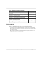
Document Conventions
The conventions shown in Table 2 apply in most cases.
Table 2: Document Conventions
Element
Convention
Key names, menu items, buttons,
and dialog box titles
Bold
File names and application names
Italics
User input, command names, system
responses (output and messages)
Monospace font
Variables
Monospace, italic font
Website addresses
Sans serif font (http://www.hp.com)
COMMAND NAMES are uppercase
unless they are case sensitive
Symbols in Text
These symbols may be found in the text of this guide. They have the following
meanings.
WARNING: Text set off in this manner indicates that failure to follow directions
in the warning could result in bodily harm or loss of life.
CAUTION: Text set off in this manner indicates that failure to follow directions could
result in damage to equipment or data.
IMPORTANT: Text set off in this manner presents clarifying information or specific instructions.
NOTE: Text set off in this manner presents commentary, sidelights, or interesting points of
information.
I Identifies a procedural step to be performed at the initiator site.
T Identifies a procedural step to be performed at the target site.
Data Replication Manager HSG80 ACS Version 8.7P Scripting User Guide
xi
About this Guide
Symbols on Equipment
Any enclosed surface or area of the equipment marked with these
symbols indicates the presence of electrical shock hazards. Enclosed
area contains no operator serviceable parts.
WARNING: To reduce the risk of injury from electrical shock hazards, do
not open this enclosure.
Any RJ-45 receptacle marked with these symbols indicates a network
interface connection.
WARNING: To reduce the risk of electrical shock, fire, or damage to the
equipment, do not plug telephone or telecommunications connectors into
this receptacle.
Any surface or area of the equipment marked with these symbols
indicates the presence of a hot surface or hot component. Contact with
this surface could result in injury.
WARNING: To reduce the risk of injury from a hot component, allow the
surface to cool before touching.
Power supplies or systems marked with these symbols indicate the
presence of multiple sources of power.
WARNING: To reduce the risk of injury from electrical shock,
remove all power cords to completely disconnect power from the
power supplies and systems.
Any product or assembly marked with these symbols indicates that the
component exceeds the recommended weight for one individual to
handle safely.
WARNING: To reduce the risk of personal injury or damage to the
equipment, observe local occupational health and safety requirements
and guidelines for manually handling material.
xii
Data Replication Manager HSG80 ACS Version 8.7P Scripting User Guide
About this Guide
Rack Stability
WARNING: To reduce the risk of personal injury or damage to the equipment, be
sure that:
• The leveling jacks are extended to the floor.
• The full weight of the rack rests on the leveling jacks.
• In single rack installations, the stabilizing feet are attached to the rack.
• In multiple rack installations, the racks are coupled.
• Only one rack component is extended at any time. A rack may become
unstable if more than one rack component is extended for any reason.
Getting Help
If you still have a question after reading this guide, contact service representatives or
visit our website.
HP Technical Support
In North America, call HP technical support at 1-800-652-6672, available 24 hours a
day, 7 days a week.
NOTE: For continuous quality improvement, calls may be recorded or monitored.
Outside North America, call HP technical support at the nearest location. Telephone
numbers for worldwide technical support are listed on the HP website:
http://thenew.hp.com.
Be sure to have the following information available before calling:
•
Technical support registration number (if applicable)
•
Product serial numbers
•
Product model names and numbers
•
Applicable error messages
•
Operating system type and revision level
•
Detailed, specific questions.
IMPORTANT: To be eligible for technical support, you must be using the DRM scripts provided
by HP as described in the User Guide in a supported configuration. Scripts that have been
modified in any way are not supported.
Data Replication Manager HSG80 ACS Version 8.7P Scripting User Guide
xiii
About this Guide
HP Website
The HP website has the latest information on this product, as well as the latest drivers.
Access the HP website at: http://thenew.hp.com/country/us/eng/storage.html. From this
website, select the appropriate product or solution.
HP Authorized Reseller
For the name of your nearest HP Authorized Reseller:
xiv
•
In the United States, call 1-800-345-1518.
•
In Canada, call 1-800-263-5868.
•
Elsewhere, see the HP website for locations and telephone numbers.
Data Replication Manager HSG80 ACS Version 8.7P Scripting User Guide
1
DRM Scripting Overview
Introduction
HP StorageWorks Data Replication Manager provides a means to prevent data loss
through the use of hardware redundancy and software data replication.
A Data Replication Manger (DRM) configuration consists of paired storage sites. The
initiator site carries out primary data processing. A target site is set up for data
replication. Data processing occurs at the initiator site and is replicated or copied to
the target site. If a significant failure occurs at the initiator site, data processing can be
resumed at the target site, where the data is intact.
In a DRM environment, a site failover makes the data available at the target site, most
likely after some type of failure or maintenance action. Failback moves data
operations back to the initiator after the initiator site has been brought back online.
Failsafe locked is an error mode you can set to cease initiator site I/O whenever the
target becomes inaccessible or the initiator unit fails. You may want to transition
between a failsafe-locked mode and normal mode to continue or resume operations at
the initiator site. This transition does not constitute a failover or failback event, but as
a resumption of operations.
Usually, to perform failover, failback, or a resumption of operations, an operator must
manually issue a complex series of command line interface (CLI) commands to a
controller. The use of scripts greatly reduces the need to issue many of these
commands manually. This can be especially beneficial with configurations containing
many remote copy sets or numerous subsystems that all need to perform actions
quickly during a crisis. You only need to run a program file to begin issuing the
appropriate CLI commands for an event action (for example, an unplanned failover).
For HP OpenVMS it is a command (com) file, for HP Tru64, IBM AIX, and Sun
Solaris it is a shell (sh) file, and for Microsoft Windows platforms it is a batch (bat)
file.
Although scripting may make procedures easier to perform, the operator must still be
able to perform failover, failback, or failsafe-mode transitions with CLI commands if
the scripts encounter an abnormal condition that prevents their satisfactory
completion.
Data Replication Manager HSG80 ACS Version 8.7P Scripting User Guide
1–1
DRM Scripting Overview
This guide explains:
•
Failover and failback planning considerations
•
How to obtain and install the necessary files needed for using scripts
•
How to set up the Command Console LUN (CCL)
•
How to customize the following files to your DRM configuration:
— Configuration generation batch, shell, and command files
— Target controller configuration files
— The application action list
•
How to run the failover, failback, and resumption of operation program files
Site Failover Basic Description
If the initiator site is no longer available, or if there is anticipated downtime that will
prevent operation at the initiator site, you must decide whether to perform a site
failover to the target site. Performing a failover enables the target site to assume the
role of the initiator and access (write/read) data until the problem is resolved and a
failback can be issued. Transferring control of system operation to the target site
ensures that there will be minimal interruption in data access after a failure.
IMPORTANT: Verify that all components at the target site are operational before you begin the
site failover.
NOTE: If you decide to perform a failover operation, keep in mind that all components must be
failed over. Therefore, if only one component fails, fixing that single component may be
preferable to performing a complete failover.
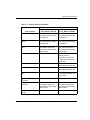
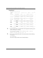
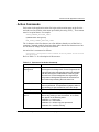
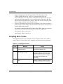
Table 1–1 outlines example criteria that calls for a failover, as well as criteria that does
not call for a failover.
1–2
Data Replication Manager HSG80 ACS Version 8.7P Scripting User Guide
DRM Scripting Overview
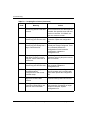
Table 1–1: Possible Failover Situations
Recommended Action
Remote Copy Set
Error_Mode = Normal
Remote Copy Set
Error_Mode = Failsafe
Total initiator site loss
Manual intervention to fail
over data and processing
to target site
Manual intervention to fail
over data and processing
to target site
Loss of initiator site
fabric
Manual intervention to fail
over data and processing
to target site
Manual intervention to fail
over data and processing
to target site
Loss of initiator controller
pair
Manual intervention to fail
over data to target site,
and restart of processing
at both sites
Manual intervention to fail
over data to target site,
and restart of processing
at both sites
Loss of all intersite links
Failover not necessary
Decide on which site
should continue
processing: continue at
inititator site or failover to
target site
Total target site loss
Failover not necessary
Manually continue
processing at initiator site
Loss of target fabric
Failover not necessary
Manually continue
processing at initiator site
Loss of target controller
pair
Failover not necessary
Manually continue
processing at initiator and
target sites
Loss of single initiator
controller
Failover not necessary
Failover not necessary
Loss of both initiator
switches
Manual intervention to fail
over data to target site,
and restart of processing
at both sites
Manual intervention to fail
over data to target site,
and restart of processing
at both sites
Loss of single initiator
switch
Failover not necessary
Failover not necessary
Type of Failure
Data Replication Manager HSG80 ACS Version 8.7P Scripting User Guide
1–3
DRM Scripting Overview
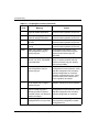
Table 1–1: Possible Failover Situations (Continued)
Recommended Action
Remote Copy Set
Error_Mode = Normal
Remote Copy Set
Error_Mode = Failsafe
Extended power outage
at initiator site
Manual intervention to fail
over data and processing
to target site
Manual intervention to fail
over data and processing
to target site
Loss of both host bus
adapters (non-clustered
hosts)
Manual intervention to fail
over data to target site,
and restart of processing
at both sites
Manual intervention to fail
over data to target site,
and restart of processing
at both sites
Loss of single disk in
redundant storage
Failover not necessary
Failover not necessary
Loss of single storageset
Failover not necessary
Failover not necessary
Loss of single host of
cluster
Failover not necessary
Failover not necessary
Type of Failure
If one host in a multi-host environment fails, you must decide whether or not a failover
is the best course of action.
When you determine that a site failover is necessary, identify which scenario best
describes your situation: planned, unplanned, or role reversal failover.
Use the planned failover procedure when failover is a scheduled event. These are
situations such as anticipated power disruption, scheduled equipment maintenance at
the local site, or the need to transfer operations to another site. Planned failovers are
further characterized as short or extended. A short, planned failover (also referred to
as prefast in the scripts) assumes the write history log will be able to accommodate the
accumulated writes for the duration of the failover. An extended, planned failover
(also referred to as prefull in the scripts) assumes the write history log will not
accommodate the accumulated writes.
An unplanned failover involves situations such as multiple controller failures, multiple
host failures, or an unplanned power outage at the local site.
A site role reversal failover transfers the initiator role to another site. The original
initiator site then assumes the role of a target site.
1–4
Data Replication Manager HSG80 ACS Version 8.7P Scripting User Guide
DRM Scripting Overview
Failback Procedure Choices
During failover, the remote copy sets at the target site are in a copy ready state,
waiting for the initiator site to become available. When a new initiator site has been
established or the original one has been restored, site operation can resume after a
failback procedure has been performed. This involves synchronizing data on both the
initiator and target subsystems so that operation can be returned to the initiator with
minimal downtime.
IMPORTANT: Verify that all components at both sites are operational before performing a
failback.
The failback sequence is a scheduled event. The HSG80 Array Controller requires that
a viable dual-redundant subsystem be available before a failback can take place.
IMPORTANT: Failback to a single controller configuration is not supported.
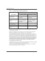
Table 1–2 can help you determine which failback procedure to use in different
circumstances.
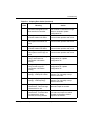
Table 1–2: Types of Failover and Failback
State of the
initiator
Failover
Failback
controller pair
type used type used
Example
Initiator site
intact
Short
Planned
Fast
Maintenance needs to be
performed at the initiator site.
The site is brought back up
when maintenance is complete
with a mini-merge from the write
history log.
Initiator site
intact
Extended
Planned
Full
Maintenance is performed at the
initiator site for a length of time
that would exceed the space on
a write history log. A failback to
the initiator after maintenance
requires a full disk copy.
Initiator site
intact
Unplanned
Full
Power goes off at initiator site.
Failover is performed to the
target site. Failback to the
initiator is performed with a full
disk copy once power is
restored.
Data Replication Manager HSG80 ACS Version 8.7P Scripting User Guide
1–5
DRM Scripting Overview
Table 1–2: Types of Failover and Failback (Continued)
State of the
initiator
Failover
Failback
controller pair
type used type used
Example
Initiator site not
intact
Unplanned
New
Hardware
Lightning strike damages
equipment, resulting in a
disaster failover. Once new
equipment is installed, a failback
is performed.
Initiator site
intact
Role
Reversal
Role
Reversal
Another site is given the initiator
role for an unspecified time. At a
later date, the initiator role
reverts back to the original site.
Summary of Failover/Failback Procedure Choices
Scripts are available for most of the failover, failback, and resumption of operation
scenarios you are likely to encounter. To perform these procedures with CLI
commands, and to find other failover and failback scenarios, refer to the HP
StorageWorks Data Replication Manager HSG80 ACS Version 8.7P Failover/Failback
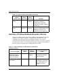
Procedures Guide. Table 1–3 lists the scripting scenarios, explains the conditions for
their use, and gives the name of the scripting procedure to follow.
Table 1–3: Failover, Failback, and Resumption of Operations
Procedure Choices
Anticipated
Initiator
Duration of
Mode of
Scripting Procedure to
Event or Condition
Event
Operation
Follow
Unplanned loss of
initiator site function.
Initiator site hardware
will not be replaced.
Unknown
Unplanned loss of target
site function.
Unknown
1–6
Normal or
failsafe
Chapter 6:
Failsafe
Chapter 7:
Unplanned Site Failover
with Full Failback
Resumption of Operations
After Unplanned Loss of
Target Site (Failsafe
Mode)
Data Replication Manager HSG80 ACS Version 8.7P Scripting User Guide
DRM Scripting Overview
Table 1–3: Failover, Failback, and Resumption of Operations
Procedure Choices (Continued)
Anticipated
Initiator
Duration of
Mode of
Scripting Procedure to
Event or Condition
Event
Operation
Follow
Unplanned loss of target
site function.
Unknown
Normal
Chapter 8:
Planned maintenance
outage at initiator site.
Short (up to
several hours)
Normal or
failsafe
Chapter 9:
Planned maintenance
outage at initiator site.
Extended
(several hours
or longer)
Normal or
failsafe
Chapter 10:
Planned maintenance at
target site.
Extended
Failsafe
Chapter 11:
Unplanned loss of
initiator site function.
Initiator site hardware
will be new.
Unknown
Planned change of
operations from initiator
site to alternate site.
Initiator site remains
operational.
Unknown
Resumption of Operations
After Unplanned Loss of
Target Site (Normal Mode)
Short Planned Site
Failover with Fast Failback
Extended Planned Site
Failover with Full Failback
Resumption of Replication
After Extended Planned
Loss of Target (Failsafe
Mode)
Normal or
failsafe
Chapter 12:
Normal or
failsafe
Chapter 13:
Unplanned Site Failover
with Failback to New
Hardware
Planned Site Role
Reversal
Data Replication Manager HSG80 ACS Version 8.7P Scripting User Guide
1–7
DRM Scripting Overview
Benefits of Scripts
The use of scripts in a DRM environment simplifies procedures from the operator’s
perspective when performing failover, failback, and resumption of operation changes.
A program file, consisting of a batch, shell, or command file, can start an entire
failover sequence. Down time is shortened by eliminating the delay between
command entries. The use of scripts also ensures that the sequence of commands has
been predetermined in a calm environment, rather than during a crisis, when mistakes
are more common. The result is a failover and failback process that is timely,
consistent, and efficient.
Components for Scripting
Scripting requires the following components:
•
The HP DRM Scripting Kit (Version 3.0) for your operating system
•
A Perl interpreter (part of the AIX, Tru64, and Solaris 8 operating systems, but
must be obtained separately for OpenVMS, Solaris 6 and 7, and Windows
NT/2000)
•
Compaq SANworks Command Scripter Version 1.0A
These components are limited to the requirements listed on page 1-14. A brief
description of each scripting component follows.
HP DRM Scripting Kit
Specific DRM Scripting Kits are available for the following operating systems:
•
HP OpenVMS
•
HP Tru64 UNIX, IBM AIX, and Sun Solaris
•
Microsoft Windows NT and Microsoft Windows 2000
These virtual “kits” consist only of files and are downloaded from the HP website.
They contain Perl scripts, Perl support files, example files, and program files
necessary for the scripts to perform failover, failback, and resumption of operation
procedures. Program files are command files (OpenVMS), shell files (AIX, Tru64,
and Solaris), and batch files (Windows NT/2000) specific to an operating system.
1–8
Data Replication Manager HSG80 ACS Version 8.7P Scripting User Guide
DRM Scripting Overview
Perl Interpreter
Perl is the interpreted programming language in which the scripts are written. The Perl
interpreter translates and processes the scripts. Every Perl script must pass through the
interpreter in order to execute.
SANworks Command Scripter
Compaq SANworks Command Scripter is application software that provides an
interface to communicate the CLI commands generated by the Perl scripts to the
HSG80 controllers via the Fibre Channel bus.
How the Failover, Failback, and Resumption of
Operation Scripts Work
This section describes how the components work together to perform failover,
failback, or resumption of operation by the use of scripts.
Perl Scripts
The scripts are written in the Perl programming language and reside on the host’s local
hard drive. For redundancy, the scripts should reside on a server at both the initiator
and target sites.
User-Customized Script Support Files
The failover, failback, and resumption of operation scripts use two user-customized
file types to provide variable information: a configuration file and an application
action list.
•
The configuration file tells the failover/failback scripts which devices are attached
to an HSG80 controller, and how the controller is configured with respect to
devices and storagesets. An example configuration generation file is provided in
the DRM Scripting Kit to allow a configuration file to be created for the
subsystem. Once created, customization is needed on the target controller
configuration files. One current configuration file for each HSG80 controller
subsystem is stored at both the initiator and target sites.
Data Replication Manager HSG80 ACS Version 8.7P Scripting User Guide
1–9
DRM Scripting Overview
•
The application action list is used by the hsg_control.pl Perl script to perform
failover, failback, and resumption of operation actions on the specified DRM
initiator-target controller pairs. For example, if you have four initiator controllers
that need to failover during a short planned failover action, then you would list the
four target controllers in the application action list. All of the controllers will fail
over together when that failover action is run.
The configuration files and the application action list are system specific. You must
tailor them to reflect your unique configuration and your failover, failback, and
resumption of operation preferences. Chapter 4, “File Customization,” provides
instructions for modifying configuration files and application action lists. These files
can then be used by the scripts to perform the necessary steps.
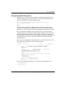
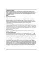
Running a Script
A script is invoked by running a command file (OpenVMS), a shell file (AIX, Solaris,
and Tru64), or a batch file (Windows NT/2000) from a command prompt on the
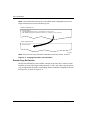
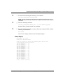
system console. Figure 1–1 shows the scripting information flow after you run one of
these program files.
1. The Perl interpreter processes the script based on the information in the
configuration file and the application action list.
2. The script reads the control table, which defines the order of CLI commands to be
issued, and sends the appropriate sequence of CLI commands (for the controller
configuration specified in the configuration file) to the Command Scripter.
3. The Command Scripter communicates the commands to the HSG80 controller
over the Fibre Channel bus and relays SHOW command verification back for the
scripts.
The area in Figure 1–1 within the dashed lines is further detailed in Figure 1–2 on
page 1-12 to show the interaction of specific failover and failback Perl scripts.
IMPORTANT: The names of remote copy sets, stripesets, mirrorsets, RAIDsets, association
sets, and connections may not contain a hyphen ( - ). This is a Perl language restriction.
Underscores ( _ ) are allowed.
1–10
Data Replication Manager HSG80 ACS Version 8.7P Scripting User Guide
DRM Scripting Overview
Server
Application
action list
Command
sequencing
Controller-pair
actions
Control
table
Fibre Channel
Perl scripts
and
interpreter
CLI commands and
device identifiers
SHOW command
verification
CLI commands
Command
Scripter
SHOW command
verification
HSG80
controller
Subsystem
configuration data
Fibre Channel
Configuration
file
CX7537B
Figure 1–1: Scripting information flow
Data Replication Manager HSG80 ACS Version 8.7P Scripting User Guide
1–11
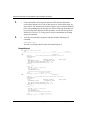
DRM Scripting Overview
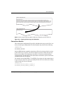
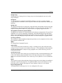
Batch, shell, or
command file
Perl interpreter
app.act
file
hsgcontrol.pl
Perl script
Called processes
drmdispatch.pl
Perl script
drmdispatch.pl
Perl script
Control
table
Configuration
file
Perl
modules
SHOW command
responses
CLI commands
SHOW command
responses
CXO7657A
Figure 1–2: Script processing
The Scripting Process Flow
Figure 1–2 shows a high-level view of the process flow for failover, failback, and
resumption of operation scripts.
1. The user runs a program file (batch, command, or shell file) to invoke the
hsgcontrol.pl Perl script.
2. The Perl interpreter processes the scripting instructions. Parameters specified in
the failover/failback program file tells the script to read the application action list
and what actions to perform. The hsgcontrol.pl script then calls the
drmdispatch.pl script.
1–12
Data Replication Manager HSG80 ACS Version 8.7P Scripting User Guide
DRM Scripting Overview
3. The drmdispatch.pl script performs the work of failover, failback, and resumption
of operation. The script is given parameters from the application action list
(app.act file) that specify how the actions are processed. The controller
configuration files and control table are read by the drmdispatch.pl script and
followed until all actions are performed. Perl modules, containing library routines,
can be accessed by the scripts when needed.
4. The drmdispatch.pl script then sends commands to the Command Scripter for
inband transmission to the controller. SHOW command responses are returned
from the controllers and used by the scripts to verify that the commands issued to
the controllers were successfully executed.
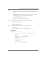
The disaster-tolerant configuration that supports DRM involves two HSG80 Array
Controller subsystems—one at an initiator site and one at a target site.
Figure 1–3 depicts a basic DRM configuration.
BuildngA
BuildngB
Host A
BuildngA
Host B
BuildngB
CXO7172A
Figure 1–3: Data Replication Manager basic configuration
This figure uses fictional “Buildng A” as the initiator site and “Buildng B” as the
target site. The scripts use the following sequence for failover and failback:
•
Failover from Buildng A to Buildng B (planned, unplanned, or role reversal)
•
Failback step 1 from Buildng B back to Buildng A (fast, full, new hardware, or
role reversal)
•
Failback step 2 from Buildng B back to Buildng A (fast, full, new hardware, or
role reversal)
Data Replication Manager HSG80 ACS Version 8.7P Scripting User Guide
1–13
DRM Scripting Overview
NOTE: The previous figure refers to Buildng A as the initiator site and Buildng B as the target
site. This does not change even after failover has occurred to Buildng B (and before failback has
occurred to Buildng A). While in failover mode, the controllers in Buildng B are acting as the
initiator for all remote copy sets and are referred to as the target in this document.
Notice that failback with the scripts is performed in two steps:
•
The first step adds the initiator back into the remote copy set. It also performs a
normalization if any new data was written to the target controllers while the
initiator was inoperable. It is often desirable for the system to operate in this
semi-failed-back state while remotely mirroring data, before reverting to the
original initiator and target roles.
•
The second step reverses the initiator and target roles.
Requirements
This section specifies the hardware and software required for DRM scripting.
Platforms
Supported platforms are:
•
HP OpenVMS Versions 7.2-1H1, 7.2-2, and 7.3
•
HP Tru64 UNIX Versions 5.1 and 5.1A
•
IBM AIX Versions 4.3.3 and 5.1
•
Microsoft Windows NT Server Version 4 with Service Pack 6a
•
Microsoft Windows 2000 Server with Service Pack 2, Advanced Server with
Service Pack 2, and Datacenter Server with Service Pack 2
•
Sun Solaris Versions 2.6, 7, and 8
The scripts work in a heterogeneous DRM environment (with the supported platforms
mentioned above) to perform site failovers, failbacks, and other related procedures.
However, the servers for a DRM initiator-target pair must be running the same
operating system.
The scripts can be run from any one of the scripting supported platforms and can
manipulate storage that presents LUNs to other DRM-supported platforms (for
example, HP-UX and Novell Netware). A Command Console LUN (CCL) or a
non-RCS LUN communicates scripting operations to the controllers. So the host
running the scripts may or may not have access to similar types of LUNs on the
controller when performing scripting operations.
1–14
Data Replication Manager HSG80 ACS Version 8.7P Scripting User Guide
DRM Scripting Overview
To manipulate storage on a platform not supported by the scripts, use a controller
shared by a host capable of running the scripts. The scripts can manipulate all storage
on a controller when communicating through a LUN.
Hardware
DRM supports compatible operating systems sharing the same HSG80 controller. To
be compatible, all of the operating systems must support the same level of SCSI
command and control: either SCSI-2 with the CCL turned on or off, or SCSI-3 with
the CCL turned on. Table 1–4 lists the current DRM-supported operating systems and
the SCSI level that each supports:
Table 1–4: DRM Heterogeneous Operating Systems
Operating System
SCSI-2
SCSI-3
HP OpenVMS
No
Yes
HP Tru64 UNIX
Yes
Yes
HP-UX
Yes
Yes
IBM AIX
Yes
Yes
Microsoft Windows NT/2000
Yes*
Yes
Novell Netware
Yes
No
Sun Solaris
Yes*
Yes*
*IMPORTANT: Although Windows can be run in SCSI-2 or SCSI-3 mode in a DRM
environment, SCSI-2 mode is only supported with no CCL enabled. When sharing a
controller in SCSI-2 mode between Windows and another operating system using a CCL,
HP recommends that scripting be performed with the Windows host.
Sun Solaris running Secure Path Version 2.1D supports SCSI-2 mode with or without a
CCL, but not SCSI-3 mode. Sun Solaris running Secure Path Version 3.0A supports
SCSI-2 or SCSI-3, but without the use of CCLs.
Data Replication Manager HSG80 ACS Version 8.7P Scripting User Guide
1–15
DRM Scripting Overview
Switch Zoning
The scripts must reside on hosts in a zone having access to the HSG80 controllers at
the initiator and target sites.
The HSG80 controller does not distinguish between commands issued from in-band
command tools (HP StorageWorks Command Console and HP OpenView Storage
Management Appliance) and commands issued out-of-band through the serial port.
Serial port commands should only be performed when the customer has restricted
commanding from other sources. Special care must be taken with the Management
Appliance, as it periodically issues polling commands that can interpret serial port
communications. All management appliances should be removed from switch zones
in which controllers are commanded through a serial port.
Software
The following software is required to use scripts to perform DRM failover, failback,
and resumption of operations:
•
HP DRM Scripting Kit, Version 3.0
•
Perl interpreter
— Open VMS: Version 5.6 (system privileges needed)
— Tru64 UNIX: Version 5.005 (part of operating system)
— IBM AIX: Version 5.5.3.0 (part of operating system)
— Windows NT/2000: ActivePerl Version 5.6.1.628, binary kit for Win32
— Solaris 6: Version 5.005 (for Intel/Solaris) or Version 5.6.1 (SPARC/Solaris)
— Solaris 7: Version 5.005 (for Intel/Solaris) or Version 5.6.1 (SPARC/Solaris)
— Solaris 8: Version 5.005 (for Intel/Solaris, part of operating system) or
Version 5.6.1 (for SPARC/Solaris, part of operating system)
1–16
•
Compaq SANworks Command Scripter, Version 1.0A
•
HP StorageWorks Array Controller Software (ACS) Version 8.7P
Data Replication Manager HSG80 ACS Version 8.7P Scripting User Guide
2
Installation
Introduction
This chapter discusses acquiring and installing software components necessary for the
scripting processes to run. The following software components are required to prepare
a server attached to a Storage Area Network (SAN) for script operation:
•
The HP DRM Scripting Kit
•
A Perl interpreter
•
The Compaq SANworks Command Scripter
These software components must be installed on each host at the initiator and target
sites that will use scripting.
HP DRM Scripting Kit
This software kit is obtained from the HP website:
http://www.compaq.com/products/sanworks/softwaredrivers/drm/index.html
The kit contains program files, Perl scripts, Perl modules, control tables, and example
files. Several kits are available for various operating systems, and they provide the
scripts to perform failover, failback, and resumption of operation procedures.
Installing the HP DRM Scripting Kit Files
The DRM Scripting Kit should be installed on an initiator and target host (at a
minimum) to provide redundancy. It can also be installed on any host to manipulate
storage through a compatible controller, but this method may not provide disaster
tolerance when a site goes offline. Use the following procedures to install the DRM
Scripting Kit on your operating systems.
NOTE: When CLONE_HOME is used in a path name in this manual, it refers to the name you
assigned to the default directory of the script files. So if you use C:\scripts as the default
directory in Windows NT/2000, a path name of %CLONE_HOME%\bin would be the same as
C:\scripts\bin.
Data Replication Manager HSG80 ACS Version 8.7P Scripting User Guide
2–1
Installation
HP OpenVMS
1. Create a directory, for example, SYS$DEVICE:[SCRIPTS], to be the default
directory for the scripts.
2. Copy the scripting kit self-extracting file (script_vms_v30.exe) into the directory
created in step 1.
3. From the command line prompt, enter the command:
RUN SCRIPT_VMS_V30.EXE
The kit files will self-extract into the default directory you created.
4. Verify that the subdirectories bin, config, log, tmp, and vms were created in the
default directory. See Appendix A for a list and description of the installed files.
5. Define the system logical name CLONE_HOME to point to the directory where
you have installed the scripts. For example:
$ DEFINE/SYSTEM/EXEC CLONE_HOME SYS$SYSDEVICE:[SCRIPTS]
To ensure this logical name is defined after the next system reboot, place this
definition in the the system startup file SYS$MANAGER:SYLOGICALS.COM.
HP Tru64 UNIX, IBM AIX, and Sun Solaris
1. Create a directory (for example, /scripts) to be a default directory for the scripts.
2. Copy the scripting kit tar file (scripts_30.tar) into the directory created in step 1.
3. From the command line, enter the following command:
tar -xvfp scripts_30.tar
The kit files will self-extract into the default directory you created.
4. Verify that the subdirectories bin, config, log, sh, and tmp were created in the
default directory. See Appendix A for a list and description of the installed files.
5. Set the environmental variable. In the ksh shell, use the following two commands:
CLONE_HOME=ScriptDefault
Example: CLONE_HOME=/scripts
export CLONE_HOME
These lines can also be added to the /.profile file to make the environmental
variable load after rebooting.
2–2
Data Replication Manager HSG80 ACS Version 8.7P Scripting User Guide
Installation
Microsoft Windows NT/2000
1. Create a directory (for example, C:\scripts) to be a default directory for the scripts.
2. Copy the scripting kit self-extracting file (script_win_30.exe) into the directory
created in step 1.
3. From Windows Explorer or a command line prompt, double-click or execute the
script_win_30.exe file. The kit files self-extract into the default directory you
created.
4. Verify that the subdirectories bat, bin, config, log, and tmp are created in the
default directory. See Appendix A for a list and description of the installed files.
5. Add an environmental variable named %CLONE_HOME% to set the default
directory of the scripts.
a. From the Windows desktop, click Start.
b. Click Settings.
c. Click Control Panel.
d. Double-click System.
e. • For Windows 2000 servers, click Advanced, then click Environment
Variables.
• For Windows NT Server, click Environment.
f.
• For Windows 2000, in the System Variables section, click New.
• For Windows NT, continue with step 5g.
g. In the dialog box, type CLONE_HOME in the Variable Name field. In the
Variable Value field, enter the path to the script default directory (for example,
C:\scripts).
h. • For Windows 2000, click OK.
• For Windows NT, click Set.
i.
Click OK until you reach the Control Panel. Close the Control Panel.
Data Replication Manager HSG80 ACS Version 8.7P Scripting User Guide
2–3
Installation
Perl Interpreter
A Perl interpreter is necessary to execute the Perl scripts, and must be installed on
each server that runs the scripts. The Tru64 UNIX, AIX, and Solaris Version 8
platforms have a Perl interpreter included with their operating systems. In the
OpenVMS, Windows NT/2000, and Solaris Versions 6 and 7 environments, the
interpreter is a component that must be separately obtained and installed. For
information on how to obtain and install a Perl interpreter for OpenVMS, Windows
NT/2000, and Sun Solaris 7, see the following sections.
HP OpenVMS
Obtaining the OpenVMS Perl Interpreter
The Perl interpreter for the OpenVMS platform can be downloaded from:
http://www.sidhe.org/vmsperl/prebuilt.html
The interpreter tested with the scripts was Perl Version 5.6.0 and is labeled as
OpenVMS Alpha 7.2-1, Dec C Sockets.
Installing the OpenVMS Perl Interpreter
Follow the OpenVMS installation instructions located on the website listed above.
Microsoft Windows NT/2000
Obtaining the Windows Perl Interpreter (ActivePerl)
The Perl interpreter for the Windows platforms can be downloaded from:
http://aspn.activestate.com/ASPN/Downloads/ActivePerl/
HP tested the scripts with the ActivePerl 5.6.1.628 MSI package for Windows.
Previous versions of the ActivePerl program are also available at the site.
Installing Windows ActivePerl
Follow the Windows installation instructions located on the Activestate website listed
above.
Windows NT Server users must have installed or must download Microsoft Windows
Installer version 1.1 or later, and must be operating with Service Pack 5 or later. No
additional software is needed for Windows 2000 servers.
2–4
Data Replication Manager HSG80 ACS Version 8.7P Scripting User Guide
Installation
Sun Solaris Versions 6 and 7
Obtaining the Sun Solaris Versions 6 and 7 Perl Interpreter
The Perl interpreter for the Sun Solaris platforms can be downloaded from:
http://www.sunfreeware.com
At the time this document was prepared there were two versions of the Solaris Perl
interpreter. Perl Version 5.6.1 was available for the SPARC/Solaris and Perl Version
5.005 was available for Intel/Solaris.
Installing the Sun Solaris Perl Interpreter
Follow the installation instructions located on the sunfreeware website listed above.
SANworks Command Scripter
The Command Scripter component provides the interface for the Perl scripts to
communicate with the HSG80 controller via the Fibre Channel bus.
Obtaining SANworks Command Scripter
To obtain the Command Scripter, contact a reseller or HP account representative.
Refer to “HP Authorized Reseller” in the “About This Guide” section for source
information.
For DRM users with a previous version of the Command Scripter, check for updates at
the following website:
http://www.comaq.com/products/sanworks/softwaredrivers/commandscripter/index.html
Installing SANworks Command Scripter
This section describes the procedures for installing the Command Scripter on
OpenVMS, Tru64, AIX, Windows NT/2000, and Solaris. The Command Scripter
must be installed on the initiator and target site servers where the scripts reside.
Data Replication Manager HSG80 ACS Version 8.7P Scripting User Guide
2–5
Installation
HP OpenVMS
The following procedure installs the Command Scripter on a OpenVMS server:
1. Mount the CD-ROM. Use the command:
MOUNT/OVERRIDE=ID DKA400:
2. Create a directory for the Command Scripter files. The following command
creates a directory named CMDSCRPT:
CREATE/DIRECTORY SYS$SYSDEVICE:[CMDSCRPT]
3. Set the directory created in the previous step as the default directory with the
following command:
SET DEFAULT SYS$SYSDEVICE:[CMDSCRPT]
4. Copy the self-extracting zip file using the following command:
COPY DKA400:[OVMS_V71]SCRPT10V.EXE *.*
5. Unzip the files with the following command:
RUN SCRPT10V.EXE
A message displays, showing that the files are unzipped.
6. Enter the following command:
DIRECTORY
The following message displays:
Directory SYS$SYSDEVICE:[CMDSCRIPT]
COMPAQ-AXPVMS-CPQCMDSCR-V0100-45-1.PCSI;1
SCRIPT10V.EXE;1
7. Install Command Scripter using the following command:
PRODUCT INSTALL CPQCMDSCR /SOURCE=[]
When asked to continue, enter Yes. Follow the on screen prompts. A verification
message is displayed.
8. When installation is complete, add the following line to the system
SYLOGIN.COM file:
CMDSCRIPT == “$CMDSCRIPT”
2–6
Data Replication Manager HSG80 ACS Version 8.7P Scripting User Guide
Installation
To run Command Scripter, you must have certain process privileges. Two in
particular are the privileges DIAGNOSE and LOG_IO. The Perl scripts must be
run from a privileged account.
Installation is complete.
HP Tru64 UNIX
The following procedure installs the Command Scripter on a Tru64 UNIX server:
1. Mount the CD-ROM using the following command:
mount -r -t cdfs -o rrip /dev/disk/cdrom0c /mnt
2. Enter the following commands:
CD /mnt
CD unix
install.sh
3. The license agreement displays. Enter Yes to accept the license agreement terms.
4. The following message displays:
Starting the Command Scripter Installation . . . . . . . .
Press Enter to continue with the installation.
The files are copied.
5. Copy cmdscript to CLONE_HOME/bin (the subdirectory under the default
directory where the DRM scripting files reside: for example, /scripts/bin).
Installation is complete.
IBM AIX
The following procedure installs the Command Scripter on an IBM AIX server:
1. Mount the CD-ROM using the following command:
mount /cdrom
2. Enter the following commands:
CD /cdrom
./install.sh
3. The license agreement displays. Enter Yes to accept the license agreement terms.
Data Replication Manager HSG80 ACS Version 8.7P Scripting User Guide
2–7
Installation
4. The following message displays:
Starting the Command Scripter Installation . . . . . . . .
Press Enter to continue with the installation.
The files are copied.
5. Copy cmdscript to CLONE_HOME/bin (the subdirectory under the default
directory where the DRM scripting files reside: for example, /scripts/bin).
Installation is complete.
Microsoft Windows NT/2000
The following procedure installs the Command Scripter on Windows NT or Windows
2000 servers:
1. Insert the Command Scripter CD-ROM. The InstallShield Wizard runs
automatically.
NOTE: If the CD-ROM does not automatically run, open Windows Explorer and click the
CD-ROM drive. Double-click the Windows folder, then double-click setup.exe.
2. From the Welcome screen, click Next.
3. The license agreement displays. Click Yes to accept the license agreement.
4. Accept the default or choose a destination for the program installation. Click
Next.
5. Click Finish. A Command Scripter program icon is added to the Programs menu.
6. Copy cmdscript.exe to %CLONE_HOME%\BIN (the subdirectory under the
default directory where the DRM scripting files reside: for example,
C:\scripts\bin).
7. The Windows version of Command Scripter requires that a controller be
configured on each storage subsystem to direct the inband Fibre Channel data.
To test the connection, use the following procedure for each controller:
a. Go to the Windows command prompt.
b. Switch to the %CLONE_HOME%\bin directory (where %CLONE_HOME%
is the name given to the default scripts directory).
2–8
Data Replication Manager HSG80 ACS Version 8.7P Scripting User Guide
Installation
c. Enter the following CLI command:
cmdscript -f DeviceName “show this_controller”
DeviceName is the LUN communicating with the controller. It can be a drive
letter (for example, Q:), or a string in the format Scsi3:1:124:0. (Refer to
“Communicating Via Command Scripter” on page 5-2.)
You will see the expected SHOW command response from the controller.
8. Take note of what drive letters correspond to each controller name. You will need
these for later configuration tasks.
Installation is complete.
Sun Solaris
The following procedure installs Command Scripter on a Sun Solaris server:
1. Insert the CD-ROM.
2. Select the UNIX folder.
3. Select install.sh.
4. Enter OK. There are no arguments. This returns the license agreement terms.
5. Enter YES. Files are copied into directories.
6. When the system installs CPQelm, select Enter.
7. Copy cmdscript to CLONE_HOME/BIN (the subdirectory under the default
directory where the DRM scripting files reside: for example, /usr/scripts/bin).
8. Close the install window and eject the CD-ROM.
Installation is complete.
Data Replication Manager HSG80 ACS Version 8.7P Scripting User Guide
2–9
Installation
2–10
Data Replication Manager HSG80 ACS Version 8.7P Scripting User Guide
3
CCL Setup
Introduction
This guide assumes that a Data Replication Manager (DRM) configuration is already
in place to allow the scripts to run. However, there are some setup procedures that are
important enough that the concepts are reiterated here to ensure a smooth transition to
the scripting environment. In particular, if the Command Console LUN (CCL) will be
used, then it must be enabled on the controller and configured so the host can make
use of it. The CCL is a special pseudo disk device on a RAID storage system that
allows the servers to communicate with the RAID array. This chapter discusses how to
set up a CCL for each supported operating system. If the CCL is not being used (for
example, a non-RCS LUN is used), then this chapter can be skipped.
The scripts reside on hosts in a zone having access to controllers at the initiator and
target sites. The following procedure shows you how to set up one CCL for each of the
platforms that support scripting. Set up another CCL for the other site controller
(initiator or target), to allow communication from either site’s host.
HP OpenVMS CCL and Job Queue Setup
OpenVMS is only supported in SCSI-3 mode. The following procedures describe
OpenVMS CCL setup and job queue setup.
HP OpenVMS CCL Setup
1. From the initiator controller, use the following command:
SET THIS_CONTROLLER IDENTIFIER=Value
The IDENTIFIER switch creates a CCL identifier that makes the controller and
the CCL visible to the host. Value is a number between 0–32766.
2. From the target controller, use the following command:
SET THIS_CONTROLLER IDENTIFIER=Value
Where the value can be a number between 0–32766 (unique for each CCL).
Data Replication Manager HSG80 ACS Version 8.7P Scripting User Guide
3–1
CCL Setup
3. From the initiator and target-site hosts, enter the following command:
MCR SYSMAN
IO AUTOCONFIGURE/LOG
4. From the host, enter the following command:
SHOW DEVICE GG
A listing of initiator and target CCLs appears in the format $1$GGAValue, where
Value is a number between 0–32766.
5. Verify that Command Scripter is working, by entering the following command
from the initiator and target hosts:
CMDSCRIPT -f $1$GGAValue “SHOW THIS_CONTROLLER”
with Value being the ID number of the initiator or target CCLs.
HP OpenVMS Job Queue Setup
•
If you have an existing batch queue you would like to use for the scripts, then
define the logical name CLONE_QUEUE to point to this queue. For example, use
the command:
DEFINE/SYSTEM CLONE_QUEUE HostName_BATCH
•
If you do not have a batch queue set up on your system, refer to the VMS System
Manager’s Manual and define one. After defining a batch queue, point to it using
the step above.
HP Tru64 UNIX CCL Setup
Tru64 is supported in SCSI-2 and SCSI-3 mode. The following steps enable the CCL
and configure it on the Tru64 UNIX platform:
1. To enable the controller CCL in SCSI-2 mode, enter the following commands
from each controller subsystem:
SET THIS_CONTROLLER SCSI_VERSION=SCSI-2
SET THIS_CONTROLLER COMMAND_CONSOLE_LUN
To enable the CCL in SCSI-3 mode, enter the following command from each
controller subsystem:
SET THIS_CONTROLLER SCSI_VERSION=SCSI-3
3–2
Data Replication Manager HSG80 ACS Version 8.7P Scripting User Guide
CCL Setup
2. Verify the CCLs can be seen by the host by entering this command (from the
host):
hwmgr -view device
The following is a sample output for this command:
HWID: Device Name
Mfg
Model
Location
-------------------------------------------------------------------------4: /dev/dmapi/dmapi
5: /dev/scp_scsi
6: /dev/kevm
44: /dev/disk/floppy0c
3.5in floppy
fdi0-unit-0
57: /dev/disk/cdrom0c
COMPAQ
CD-224E
bus-2-targ-0-lun-0
58: /dev/disk/dsk0c
COMPAQ
BC03662379
bus-6-targ-3-lun-0
62: /dev/cport/scp1
HSG80CCL
bus-1-targ-3-lun-0
63: /dev/cport/scp2
HSG80CCL
bus-0-targ-0-lun-0
70: /dev/disk/dsk9c
DEC
HSG80
IDENTIFIER=1509
71: /dev/disk/dsk10c
DEC
HSG80
IDENTIFIER=1529
The device names of the CCLs in this example are scp1 and scp2. To verify which
controller (remote copy name) uses a CCL, enter the command:
cmdscript -f DeviceName "show this_controller”
The resulting sample output describes the controller and its remote copy name:
Controller:
HSG80 ZG02103566 Software V87P, Hardware E12
NODE_ID
= 5000-1FE1-0009-0EC0
ALLOCATION_CLASS = 0
SCSI_VERSION
= SCSI-3
Configured for MULTIBUS_FAILOVER with ZG02103685
In dual-redundant configuration
Device Port SCSI address 6
Time: 23-OCT-2001 10:33:10
Command Console LUN is lun 0 (IDENTIFIER = 1500)
Host Connection Table is NOT locked
Smart Error Eject Disabled
Host PORT_1:
Reported PORT_ID = 5000-1FE1-0009-0EC1
PORT_1_TOPOLOGY = FABRIC (fabric up)
Address
= 6F1900
Host PORT_2:
Reported PORT_ID = 5000-1FE1-0009-0EC2
PORT_2_TOPOLOGY = FABRIC (fabric up)
Address
= 6F1B00
REMOTE_COPY = HSG015I
Cache:
256 megabyte write cache, version 0022
Cache is GOOD
No unflushed data in cache
CACHE_FLUSH_TIMER = DEFAULT (10 seconds)
Mirrored Cache:
256 megabyte write cache, version 0022
Cache is GOOD
No unflushed data in cache
Data Replication Manager HSG80 ACS Version 8.7P Scripting User Guide
3–3
CCL Setup
Battery:
NOUPS
FULLY CHARGED
Expires:
29-AUG-2003
IBM AIX CCL Setup
AIX is supported in SCSI-2 and SCSI-3 mode. The following steps enable the CCL
and configure it on the IBM AIX platform:
1. To enable the controller CCL in SCSI-2 mode, enter the following command from
each controller subsystem:
SET THIS_CONTROLLER SCSI_VERSION=SCSI-2
SET THIS_CONTROLLER COMMAND_CONSOLE_LUN
2. To enable the CCL in SCSI-3 mode, enter the following command from each
controller subsystem:
SET THIS_CONTROLLER SCSI_VERSION=SCSI-3
3. Verify that the CCL is enabled by entering the following command from each
controller subsystem:
SHOW THIS_CONTROLLER
The following is a sample output showing that the CCL is enabled:
Controller:
HSG80 ZG05103470 Software V87P, Hardware E12
NODE_ID
= 5000-1FE1-0009-0A40
ALLOCATION_CLASS = 0
SCSI_VERSION
= SCSI-3
Configured for MULTIBUS_FAILOVER with ZG05103641
In dual-redundant configuration
Device Port SCSI address 6
Time: 13-DEC-2001 08:57:54
Command Console LUN is lun 0 (IDENTIFIER = 10)
.
.
.
4. Verify that CCLs can be seen by the host by entering the command (from the
host):
lsdev -Cc disk
The following sample output verifies the host recognizes the CCL:
hdisk0 Available 10-60-00-6,0
hdisk1 Available 20-58-00-6,0
hdisk2 Available 20-58-00-6,1
3–4
16 Bit LVD SCSI Disk Drive
DEC HSG80 Command Console LUN
DEC HSG80 RAID Array
Data Replication Manager HSG80 ACS Version 8.7P Scripting User Guide
CCL Setup
Microsoft Windows NT/2000 CCL Setup
Windows supports the CCL in SCSI-3 mode only. The following steps enable the CCL
and configure it on a Windows platform:
1. To enable the CCL, enter the following command from each controller subsystem:
SET THIS_CONTROLLER SCSI_VERSION=SCSI-3
2. Check which CCLs can be seen by entering the following command from each
host used by the scripts.
CMDSCRIPT -F SUBSYSDATA
The system displays a list of CCLs similar to the following:
Available devices:
Device Name
Scsi4:1:0:0
Scsi4:1:2:0
Scsi5:1:1:0
Scsi5:1:3:0
Vendor
DEC
DEC
DEC
DEC
Product ID
HSG80CCL
HSG80CCL
HSG80CCL
HSG80CCL
Serial Num
ZG91412410
ZG91205687
ZG91416136
ZG91606296
FW
V87P
V87P
V87P
V87P
3. To ensure that a host can see the CCL, enter the following command, using a
device name like one of those shown in the example display in the previous step:
CMDSCRIPT -F DeviceName "SHOW THIS_CONTROLLER"
Example: cmdscript -f Scsi4:1:0:0 "show this_controller"
The resulting display should show all the characteristics of the controller,
verifying that the host sees the CCL.
Sun Solaris CCL Setup
Sun Solaris supports the CCL when running Secure Path Version 2.1D in SCSI-2
mode and SCSI-3 mode. A CCL is not supported with Secure Path Version 3.0, so
non-RCS LUNs must be used to communicate with the controller.
To enable the controller CCL in SCSI-2 mode with Secure Path Version 2.1D, enter
the following command from each controller subsystem:
SET THIS_CONTROLLER SCSI_VERSION=SCSI-2
SET THIS_CONTROLLER COMMAND_CONSOLE_LUN
To enable the CCL in SCSI-3 mode with Secure Path Version 2.1D, enter the
following command from each controller subsystem:
SET THIS_CONTROLLER SCSI_VERSION=SCSI-3
Data Replication Manager HSG80 ACS Version 8.7P Scripting User Guide
3–5
CCL Setup
The following sections describe file changes needed when running Secure Path
Version 2.1D with Sun Solaris.
/kernel/drv/sd.conf
All Secure Path devices must have a corresponding sd target entry. Secure Path creates
its own sd.conf entries, one per targN of the ldLite.conf file entries. These entries are
placed at the head of the sd.conf file and allow Secure Path devices to configure prior
to other sd targets. Placing the ldLite entries at the head of the sd.file prevents conflicts
between Secure Path entries and other SCSI bindings.
Secure Path entries have the format:
name="sd" parent="ldLite" target=N lun=0;
where N represents the value of targN-dev-Name in ldLite.conf.
For example, Secure Path device target 20 would have the following entry:
name="sd" parent="ldLite" target=20 lun=0;
When you add or remove Secure Path units and LUNs, you must also add or remove
the entries for them in sd.conf.
Entries to mda.conf and LdLite.conf
Entries to the CCL in the mda.conf, ldLite.conf, and sd.conf files are similar to other
LUNs with the following differences:
•
mda.conf
The LUN ID assigned to the CCL can be determined by issuing the following CLI
command:
show this_controller
The LUN ID assigned to the CCL is displayed in the controller data and is usually
LUN 0. Similar to any storage LUN on the RAID storage system, there must be
two entries for each CCL in mda.conf—one for each path.
An example of an entry in mda.conf containing an initiator CCL is:
name="mda" parent="/pci@1f,4000/fibre-channel@2" target=33 lun=0 qdepth=32;
name="mda" parent="/pci@1f,4000/fibre-channel@4" target=32 lun=0 qdepth=32;
An example of an entry in mda.conf containing a target CCL is:
name="mda" parent="/pci@1f,4000/fibre-channel@2" target=35 lun=0 qdepth=32;
name="mda" parent="/pci@1f,4000/fibre-channel@4" target=34 lun=0 qdepth=32;
3–6
Data Replication Manager HSG80 ACS Version 8.7P Scripting User Guide
CCL Setup
•
ldLite.conf
The World Wide LUN ID that is needed in ldLite.conf is created by appending the
Node ID of the RAID storage system with the hexadecimal equivalent of the SCSI
ID of the CCL device (HSG80CCL).
You can determine the Node ID by issuing the CLI command:
show this_controller
The Node ID is a 16-character hexadecimal value displayed as the NODE_ID in
the controller data. The SCSI ID of the CCL must also be converted to a
hexadecimal value. The hexadecimal value for HSG80CCL is
4853-4738-3043-434C.
For example, to assign the CCL to target 20 of a StorageWorks HSG80 Storage
System with a Node ID of 5000-1FE1-0001-ED10, ldLite.conf must have the
following entry:
targ20-devName="5000-1FE1-0001-ED10-4853-4738-3043-434C"
Reboot the servers with the command reboot -- -r. You should now be able
to see the CCLs using the format command.
Data Replication Manager HSG80 ACS Version 8.7P Scripting User Guide
3–7
CCL Setup
3–8
Data Replication Manager HSG80 ACS Version 8.7P Scripting User Guide
4
File Customization
Introduction
This chapter takes you through the customizations required for the configuration
generation files, target controller configuration files, and the application action list.
These customizations must be made to files on both the initiator and target hosts so the
scripts may be run from either site for redundancy.
File Customization Steps
The following list summarizes the file configuration process explained in this chapter.
•
Create executable files to simplify the configuration generation task (see
“Configuration Generation File Creation” on page 4-3). One executable
configuration generation file is created for each controller subsystem on each host.
The executable files are run on each host to create initiator and target controller
configuration files.
•
Execute the configuration generation file for each controller subsystem. See
“Running Configuration Generation Files” on page 4-17.
•
Use pertinent information from the initiator configuration files to copy into, or
otherwise modify, the respective target configuration files. See “Target Controller
Configuration File Customization” on page 4-19. Customizations to the target
configuration files are:
— Copy association set information from initiator configuration files to the target
configuration files.
— Copy remote copy set information from the initiator configuration files to the
target configuration files.
— Identify and add target-site hosts that are granted access to remote copy set
units following a failover.
— Modify the read and write cache values in the target configuration files to
maintain consistent values with the initiator configuration files.
Data Replication Manager HSG80 ACS Version 8.7P Scripting User Guide
4–1
File Customization
•
Modify the application action list (app_ex.act file) to specify all DRM
initiator-target controller pairs that you want to execute concurrently in the SAN.
See “Application Action List Customization” on page 4-23.
IMPORTANT: The names of remote copy sets, stripesets, mirrorsets, RAIDsets, association
sets, and connection names may not contain a hyphen ( - ). This is a Perl restriction.
Underscores ( _ ) are allowed.
Table 4–1 lists the files created or customized on the initiator and target hosts while
performing the procedures in this chapter. A configuration generation file for each
controller subsystem is created on both hosts and saved in the BAT, SH, or VMS
subdirectory of CLONE_HOME (the name of the directory where the scripts reside),
depending on your operating system. The .xxx file extension denotes a filename
ending with .com (OpenVMS), .sh (Tru64 UNIX, AIX, and Solaris), or .bat
(Windows).
Table 4–1: Created or Customized Host Files
Initiator Host
Subdirectory
File
bat, sh, or
vms
InitiatorName_gen.xxx
bat, sh, or
vms
TargetName_gen.xxx
config
InitiatorName.cfg
Example:
tulsa_gen.bat
Example:
fargo_gen.bat
Target Host
Subdirectory
bat, sh, or
vms
InitiatorName_gen.xxx
bat, sh, or
vms
TargetName_gen.xxx
config
InitiatorName.cfg
Example: tulsa.cfg
config
TargetName.cfg
app.act
Example:
tulsa_gen.bat
Example:
fargo_gen.bat
Example: tulsa.cfg
config
Example: fargo.cfg
config
File
TargetName.cfg
Example: fargo.cfg
config
app.act
The generation files you create are run on each host to create initiator and target
controller configuration files. These will have a .cfg extension and will be saved in the
config subdirectory.
On each host, customization occurs on two types of files: the target controller
configuration files (TargetName.cfg) on the initiator and target hosts, and the
application action list (app.act). When you are finished, the files on the initiator host
and target host are nearly identical.
4–2
Data Replication Manager HSG80 ACS Version 8.7P Scripting User Guide
File Customization
Configuration Generation File Creation
During installation of the DRM Scripting Kit for a specific operating system, one of
three types of example configuration generation files were extracted and placed in a
CLONE_HOME subdirectory (where CLONE_HOME is the default directory where
the scripts reside).
•
OpenVMS files reside in the vms subdirectory.
•
Tru64 UNIX, AIX, and Solaris files reside in the sh subdirectory
•
Windows files reside in the bat subdirectory
The example configuration generation file (gen_ex.xxx, where .xxx is the bat, sh, or
com file extension) is provided as a template file. It must be modified to create one
customized configuration generation file for each HSG80 controller subsystem at both
the initiator and target sites. The syntax of the configuration generation file differs,
depending on the operating system and whether a CCL or non-RCS LUN is used. The
modified template file is saved as an executable program file and then run at the
initiator site, and again at the target site, to create individual controller configuration
files on all hosts that will use the scripts.
Before creating configuration files for your scripts, ensure that your DRM
configuration is correctly set up. For example, check that you have an association set
with a log disk for the initiator site, that all remote copy sets belong to an association
set, a log disk is available for the target site, or any other desired setup properties are
enabled. Also check that each unit has a preferred path at both the initiator and target
sites.
IMPORTANT: Any time your controller configuration changes, the controller configuration
generation program files you create will have to be run again to create new controller
configuration files.
HP OpenVMS
The following procedure describes how to create initiator and target configuration
generation files in SCSI-3 mode when using a CCL.
1. Modify the gen_ex.com file to create an initiator configuration generation file for
the initiator site. Use a text editor and make the necessary modifications using the
following syntax:
perl -I CLONE_HOME [.BIN]generate_cfg.pl com=cs RemoteCopyName idnum
where,
Data Replication Manager HSG80 ACS Version 8.7P Scripting User Guide
4–3
File Customization
RemoteCopyName identifies the initiator DRM controller (remote copy) name of
the subsystem (for example, tulsa). The remote copy name can be obtained from
running a SHOW THIS command from the controller.
idnum specifies the device identification number for the operating system that
Command Scripter uses to communicate with initiator controller tulsa. As shown
in Figure 4–1, this is the identification number of the CCL for the local controller
(Controller A) communicating with the initiator host (Host A).
In OpenVMS, the device identification number can be obtained by entering the
command:
SHOW DEVICE GG
A listing of CCLs appears in the format $1$GGAValue, where Value is a number
between 1-9999. An example of a valid device identification number would be
$1$GGA3001.
NOTE: The disk identifier, or Value, can be any decimal number from 0 to 32766, except Mass
Storage Control Protocol (MSCP)-served devices. If the Fibre Channel disk device is MSCPserved, the device identifier is limited to 9999.
2. Save the edited generation file into the CLONE_HOME/vms subdirectory with a
meaningful name like tulsa_gen.com.
3. Modify the gen_ex.com file again to create a target configuration generation file
for the initiator site. The device identification number used in this file specifies the
device identification number for the CCL of the controller at the target site
(Controller B) communicating with the initiator host (Host A). Use the syntax:
perl -I CLONE_HOME [.BIN]generate_cfg.pl com=cs RemoteCopyName idnum
RemoteCopyName identifies the target DRM controller (remote copy) name of the
subsystem (for example, fargo).
idnum specifies the device identification number for the operating system that
Command Scripter uses to communicate with target controller fargo. As shown in
Figure 4–1, this is the identification number of the CCL for the remote controller
(Controller B) communicating with the initiator host (Host A).
4–4
Data Replication Manager HSG80 ACS Version 8.7P Scripting User Guide
File Customization
Setup for One Controller Subsystem
Initiator Site
Target Site
Host A
Host B
CCL
Controller A
CCL
Controller B
Setup for Maximum Controllers Per Host
Initiator Site
Target Site
Host A
Host B
CCL
Controller A
CCL
Controller C
CCL
Controller B
CCL
Controller D
CCL
Controller E
CCL
Controller F
CXO7733A
Figure 4–1: Generation file setup using a CCL
Data Replication Manager HSG80 ACS Version 8.7P Scripting User Guide
4–5
File Customization
4. Save this program file in the vms subdirectory with a meaningful name like
fargo_gen.com.
5. Repeat the above steps to create initiator and target configuration generation files
for the target site. Use the correct device identification numbers of the CCLs
communicating with the controllers. Save these files in the vms subdirectory on
the target host using the same naming convention as used previously.
HP Tru64 UNIX
The following procedure describes how to create initiator and target configuration
generation files when using a CCL in SCSI-2 or SCSI-3 mode.
1. Modify the gen_ex.sh file to create an initiator configuration generation file for the
initiator site. Use a text editor and make the necessary modifications using the
following syntax:
perl -I $CLONE_HOME $CLONE_HOME/bin/generate_cfg.pl com=cs
RemoteCopyName idnum
where,
RemoteCopyName identifies the DRM controller (remote copy) name of the
initiator subsystem (for example, tulsa). This name is case sensitive in Tru64
UNIX and must match the case of the name used later when configuring the
application action list.
idnum specifies the device identification number for the operating system that
Command Scripter uses to communicate with controller tulsa. As shown in
Figure 4–1, this is the identification number of the CCL for the local controller
(Controller A) communicating with the initiator host (Host A).
In Tru64 UNIX, the device identification number can be obtained by entering the
command:
hwmgr -view device
The resulting output shows the CCLs (see “HP Tru64 UNIX CCL Setup” on
page 3-2. The device identification number or “idnum” in that example is scp1.).
To find the controller remote copy name for a particular CCL, enter the following
command from the bin subdirectory of CLONE_HOME:
cmdscript -f DeviceName “show this_controller”
2. Save the edited shell file into the $CLONE_HOME/sh subdirectory with a
meaningful name like tulsa_gen.sh.
4–6
Data Replication Manager HSG80 ACS Version 8.7P Scripting User Guide
File Customization
3. Modify the gen_ex.sh file again to create a target configuration generation file for
the initiator site. The device identification number used in this file specifies the
device identification number for the CCL of the controller at the target site
(Controller B) with access to the initiator host (Host A). Use the syntax:
perl -I $CLONE_HOME $CLONE_HOME/bin/generate_cfg.pl com=cs
RemoteCopyName idnum
where,
RemoteCopyName identifies the DRM controller (remote copy) name of the target
subsystem (for example, fargo). This name is case sensitive in Tru64 UNIX and
must match the case of the name used later when configuring the application
action list.
idnum specifies the device identification number for the operating system that
Command Scripter uses to communicate with controller fargo. As shown in
Figure 4–1, this is the identification number of the CCL for the remote controller
(Controller B) communicating with the initiator host (Host A).
4. Save this program file in the sh subdirectory with a meaningful name like
fargo_gen.sh.
5. Repeat the above steps to create initiator and target configuration generation
program files for the target site. Use the correct device identification numbers of
the CCLs communicating with the controllers. Save these generation files in the
sh subdirectory on the target host using the same naming conventions used
previously.
IBM AIX
The following procedure describes how to create initiator and target configuration
generation files when using a CCL in either SCSI-2 or SCSI-3 mode.
1. Modify the gen_ex.sh file to create an initiator configuration generation file for the
initiator site. Use a text editor and make the necessary modifications using the
following syntax:
perl -I $CLONE_HOME $CLONE_HOME/bin/generate_cfg.pl com=cs
RemoteCopyName idnum
where,
Data Replication Manager HSG80 ACS Version 8.7P Scripting User Guide
4–7
File Customization
RemoteCopyName identifies the DRM controller (remote copy) name of the
initiator subsystem (for example, tulsa). This name is case sensitive in IBM AIX
and must match the case of the name used later when configuring the application
action list.
idnum specifies the device number for the operating system that Command
Scripter uses to communicate with controller tulsa. As shown in Figure 4–1, this
is the device number of the CCL for the local controller (Controller A)
communicating with the initiator host (Host A).
To find the idnum, use the lsdev -Cc disk command to find the device
assigned to the CCL. A listing of all available hdisks appears with those that are
CCLs identified as such. So for this example, the idnum for an hdisk CCL might
be:
/dev/hdisk1
To verify that this is the correct controller subsystem to which this device
communicates, enter the following command:
cmdscript -f /dev/hdisk1 “show this”
The resulting display shows the characteristics of the controller beginning with the
controller (remote copy) name. If a typical show this_controller response
is not received, then an incorrect idnum was used for that controller.
2. Save the edited generation file into the $CLONE_HOME/sh subdirectory with a
meaningful name like tulsa_gen.sh.
3. Modify the gen_ex.sh file again to create a target configuration generation file for
the initiator site. The device identification number used in this file specifies the
device identification number for the CCL of the controller at the target site
(Controller B) communicating with the initiator host (Host A). Use the syntax:
perl -I $CLONE_HOME $CLONE_HOME/bin/generate_cfg.pl com=cs
RemoteCopyName idnum
where,
RemoteCopyName identifies the target DRM controller (remote copy) name of the
target subsystem (for example, fargo). This name is case sensitive in IBM AIX
and must match the case of the name used later when configuring the application
action list.
idnum specifies the device number for the operating system that Command
Scripter uses to communicate with controller fargo. As shown in Figure 4–1, this
is the device number of the CCL for the remote controller (Controller B)
communicating with the initiator host (Host A).
4–8
Data Replication Manager HSG80 ACS Version 8.7P Scripting User Guide
File Customization
4. Save this program file in the sh subdirectory with a meaningful name like
fargo_gen.sh.
5. Repeat the above steps to create initiator and target configuration generation
program files for the target site. Use the correct device identification numbers of
the CCLs communicating with the controllers. Save these program files in the sh
subdirectory on the target host using the same naming conventions used
previously.
Microsoft Windows NT/2000
Windows NT/2000 can be run in SCSI-2 mode with no CCLs or in SCSI-3 mode with
CCLs. The following procedures show how to use either method.
SCSI-2 Mode with No CCL Enabled
In SCSI-2 mode (with no CCL enabled), the scripting hosts communicate with
controllers through LUNs. These must be non-RCS LUNs with “sticky” drive letters,
meaning that they are persistent during restarts of the host. Hosts at the initiator and
target sites must see these LUNs as the same drive letter. For example, if Host A
(initiator) sees this LUN as Q:, then Host B (target) must see the same LUN as Q: also
(refer to Figure 4–2.). There is a maximum limit of three controllers per host. Follow
these steps to create SCSI-2 initiator and target controller generation batch files:
1. Ensure you have one non-RCS LUN enabled on each initiator and target controller
subsystem that each host running the scripts can access (see Figure 4–2). This
means that the initiator host must have access to LUNs at the initiator and target
sites, and the target host has access to LUNs at the initiator and target sites. If
zoning is enabled, make sure the initiator and target hosts reside in the same zone.
2. Modify the gen_ex.bat file to create an initiator configuration generation file for
each initiator site controller. Use a text editor and make the necessary
modifications using the following syntax:
Perl -I %CLONE_HOME% %CLONE_HOME%\bin\generate_cfg.pl com=cs
RemoteCopyName Device:
where,
RemoteCopyName identifies the DRM controller (remote copy) name of the
initiator subsystem (for example, tulsa). The remote copy name can be obtained
by running a SHOW THIS command from the controller.
Device: specifies the non-RCS LUN that Command Scripter uses to communicate
with the initiator controller from the initiator host (for example, Q: in Figure 4–2).
Data Replication Manager HSG80 ACS Version 8.7P Scripting User Guide
4–9
File Customization
Setup for One Controller Subsystem
Initiator Site
Target Site
Host A
Host B
Controller A
Controller B
Q:
R:
Setup for Maximum Controllers Per Host
Initiator Site
Target Site
Host A
Host B
Controller A
Controller B
Q:
G:
K:
R:
Controller C
Controller E
Controller D
Controller F
H:
L:
CXO7732A
Figure 4–2: Generation file setup with a non-RCS LUN
4–10
Data Replication Manager HSG80 ACS Version 8.7P Scripting User Guide
File Customization
3. Save the edited initiator configuration generation batch file into the
%CLONE_HOME%\bat subdirectory with a meaningful name like tulsa_gen.bat.
4. Modify the gen_ex.bat file again to create a target configuration generation file for
the initiator site. The syntax is:
Perl -I %CLONE_HOME% %CLONE_HOME%\bin\generate_cfg.pl com=cs
RemoteCopyName Device:
where,
RemoteCopyName identifies the DRM controller (remote copy) name of the target
subsystem (for example, fargo).
Device: specifies the non-RCS LUN that Command Scripter uses to communicate
with the target controller from the initiator host (for example, R: in Figure 4–2).
5. Save this batch file in the BAT subdirectory with a meaningful name like
fargo_gen.bat.
6. Repeat the above steps to create initiator and target configuration generation batch
files for all hosts running scripts at the target site. Use the correct non-RCS LUN
device letters that provide communications to the controllers. Save these batch
files in the BAT subdirectory on the target host using the same naming convention
used previously.
SCSI-3 Mode with CCLs
In SCSI-3 mode, the Windows scripting hosts communicate with controllers through
CCLs. Chapter 3 describes how to set up CCLs and identify their serial numbers.
Follow these steps to create initiator and target controller generation batch files:
1. Modify the gen_ex.bat file to create an initiator controller configuration
generation file for each host running scripts at the initiator site. Use a text editor
and make the necessary modifications using the following syntax:
Perl -I %CLONE_HOME% %CLONE_HOME%\bin\generate_cfg.pl com=cs
RemoteCopyName SerNum
where,
RemoteCopyName identifies the DRM controller (remote copy) name of the
initiator subsystem (for example, tulsa). The remote copy name can be obtained
by running a SHOW THIS command from the controller.
Data Replication Manager HSG80 ACS Version 8.7P Scripting User Guide
4–11
File Customization
SerNum specifies the device serial number that Command Scripter uses to
communicate with initiator controller tulsa. As shown in Figure 4–1, this is the
serial number of the CCL for Controller A (tulsa) that is communicating with
Host A. The maximum limit is three controllers per host.
One way to find the serial number of a controller CCL would be by using the
following steps:
a. Enter the command:
CMDSCRIPT -F SUBSYSDATA
A listing of available controller devices will display, similar to the following:
Available devices:
Device Name
Scsi4:1:0:0
Scsi4:1:2:0
Scsi5:1:1:0
Scsi5:1:3:0
Vendor
DEC
DEC
DEC
DEC
Product ID
HSG80CCL
HSG80CCL
HSG80CCL
HSG80CCL
Serial Num
ZG91412410
ZG91205687
ZG91416136
ZG91606296
FW
V87P
V87P
V87P
V87P
This output display shows CCLs that may be within the same controller
subsystem pair. For example, the first and third device listed above may be
tulsa_top and tulsa_bot.
b. Cross-reference the device serial number to the controller name using the
following command:
CMDSCRIPT -F DeviceName “SHOW THIS”
Example: cmdscript -f Scsi4:1:0:0 “show this”
The resulting display shows the characteristics of the controller, beginning with
the controller name. For example,
tulsa_bot>
As shown in the first line of the listing in step 1a, you now know that the serial number
for the bottom controller of tulsa is ZG91412410 by cross-referencing the device
name, controller name, and serial number.
NOTE: Scripts may be run from either the top or bottom controller of a controller subsystem
pair. So the scripts for controller tulsa can be run from the top or bottom controller of tulsa.
2. Save the edited initiator configuration generation batch file into the
%CLONE_HOME%\bat subdirectory with a meaningful name like tulsa_gen.bat.
3. Modify the gen_ex.bat file again to create a target configuration generation file for
the initiator site. The syntax is:
Perl -I %CLONE_HOME% %CLONE_HOME%\bin\generate_cfg.pl com=cs
RemoteCopyName SerNum
4–12
Data Replication Manager HSG80 ACS Version 8.7P Scripting User Guide
File Customization
where,
RemoteCopyName identifies the DRM controller (remote copy) name of the target
subsystem (for example, fargo). The remote copy name can be obtained by
running a SHOW THIS command from the controller.
SerNum specifies the device serial number that Command Scripter uses to
communicate with target controller fargo from the initiator host. As shown in
Figure 4–1, this is the serial number of the CCL for Controller B (fargo) that is
communicating with Host A.
4. Save this batch file in the BAT subdirectory with a meaningful name like
fargo_gen.bat.
5. Repeat the above steps to create initiator and target configuration generation batch
files for each host running the scripts at the target site. Save these batch files in the
BAT subdirectory on the target host using the same naming convention used
previously.
Sun Solaris
Solaris can run using the CCL in SCSI-2 or SCSI-3 mode with Secure Path
Version 2.1D. Solaris cannot use the CCL with Secure Path Version 3.0, so it must use
a non-RCS LUN. The following procedures show how to use either method.
Using the CCL
1. Modify the gen_ex.sh file to create an initiator controller configuration generation
file for each host running the scripts at the initiator site. Use a text editor and make
the necessary modifications using the following syntax:
perl -I $CLONE_HOME $CLONE_HOME/bin/generate_cfg.pl com=cs
RemoteCopyName idnum
where,
RemoteCopyName identifies the DRM controller (remote copy) name of the
subsystem (for example, tulsa). This name is case sensitive in Sun Solaris and
must match the case of the name used later when configuring the application
action list.
idnum specifies the device number for the operating system that Command
Scripter uses to communicate with controller tulsa. As shown in Figure 4–1, this
is the device number of the CCL for the local controller (Controller A)
communicating with the initiator host (Host A).
Data Replication Manager HSG80 ACS Version 8.7P Scripting User Guide
4–13
File Customization
To find the idnum, use the format command to find the device assigned to the
CCL. For example, the format entry displayed would look like the following:
c1t100d0 <drive type unknown>
So for this example, the entry for idnum would be:
/dev/rdsk/c1t100d0s2
where s2 is the slice number of the drive.
2. Save the edited generation file into the $CLONE_HOME/sh subdirectory with a
meaningful name like tulsa_gen.sh.
3. Modify the gen_ex.sh file again to create a target configuration generation file for
the initiator site. The device identification number used in this file specifies the
device identification number for the CCL of the controller on the target site
(Controller B) communicating with the initiator host (Host A). Use the syntax:
perl -I $CLONE_HOME $CLONE_HOME/bin/generate_cfg.pl com=cs
RemoteCopyName idnum
where,
RemoteCopyName identifies the target DRM controller (remote copy) name of the
subsystem (for example, fargo). This name is case sensitive in Sun Solaris and
must match the case of the name used later when configuring the application
action list.
idnum specifies the device number for the operating system that Command
Scripter uses to communicate with controller fargo. As shown in Figure 4–1, this
is the device number of the CCL for the remote controller (Controller B)
communicating with the initiator host (Host A).
4. Save this program file in the sh subdirectory with a meaningful name like
fargo_gen.sh.
5. Repeat the above steps to create initiator and target configuration generation
program files for all hosts running the scripts at the target site. Use the correct
device identification numbers of the CCLs communicating with the controllers.
Save these program files in the sh subdirectory on the target host using the same
naming conventions used previously.
4–14
Data Replication Manager HSG80 ACS Version 8.7P Scripting User Guide
File Customization
Using the Non-RCS LUN (No CCL)
1. Modify the gen_ex.sh file to create an initiator configuration generation file for
each host running the scripts at the initiator site. Use a text editor and make the
necessary modifications using the following syntax:
perl -I $CLONE_HOME $CLONE_HOME/bin/generate_cfg.pl com=cs
RemoteCopyName DeviceID
where,
RemoteCopyName identifies the DRM controller (remote copy) name of the
subsystem (for example, tulsa). This name is case sensitive in Solaris and must
match the case of the name used later when configuring the application action list.
DeviceID specifies the identifier for the non-RCS LUN you created to allow
Command Scripter to communicate with the initiator controller tulsa. The setup is
similar to that shown in Figure 4–2, where instead of a drive letter, this is the
device identifier of the LUN for the local controller (Controller A) communicating
with the initiator host (Host A). The device identifier can be found using the
following method.
Run a SHOW CLI command on the non-RCS LUN you created and note the LUN
ID (or WWLUN_ID) number. See the following example:
TULSA TOP ->show d34
LUN
Uses
Used by
-------------------------------------------------------------------------D34
DISK50100
(partition)
LUN ID:
6000-1FE1-0009-0A30-0001-0280-4798-00B3
NOIDENTIFIER
Switches:
RUN
NOWRITE_PROTECT
READ_CACHE
READAHEAD_CACHE
WRITEBACK_CACHE
MAX_READ_CACHED_TRANSFER_SIZE = 128
MAX_WRITE_CACHED_TRANSFER_SIZE = 128
Access:
TgtHost1_HBA, TgtHost2_HBA, InitHost1_HBA, InitHost2_HBA
State:
ONLINE to this controller
Not reserved
NOPREFERRED_PATH
Host Based Logging NOT Specified
Size:
4442290 blocks
Geometry (C/H/S): ( 1315 / 20 / 169 )
Next, run the following commands to get a listing of all recognized devices:
cd /opt/CPQswsp/bin
./spmgr display
Data Replication Manager HSG80 ACS Version 8.7P Scripting User Guide
4–15
File Customization
A listing of all devices similar to the following displays:
Server: SUN002
Report Created: Thu, Dec 13 16:14:03 2001
Command: ./spmgr display
= = = = = = = = = = = = = = = = = = = = = = = = = = = = = = = =
Storage: 5000-1FE1-0009-0D90
Load Balance: Off Auto-restore: Off
Path Verify: On
Verify Interval: 30
HBAs: fca-pci-0 fca-pci-1 fca-pci-4 fca-pci-5
Controller: ZG05103924, Operational
ZG02103935, Operational
Devices: c6t0d0 c6t0d1 c6t0d2 c6t0d6 c6t0d3 c6t0d4 c6t0d5
.
.
.
TGT/LUN
Device
WWLUN_ID
Parent
#_Paths
0/ 0
c7t0d0
6000-1FE1-0009-0A30-0001-0280-4798-00B3
4
.
.
.
Locate your device by matching the WWLUN_ID of this display with the LUN ID
obtained from the previous SHOW command. The device indentifier is listed for
the non-RCS LUN (for example, c7t0d0) and is used to create the necessary
DeviceID syntax for the configuration generation file as follows:
/dev/rdsk/c7t0d0s2
where s2 is the slice number of the drive.
To verify that this is the correct controller subsystem to which this device
communicates, enter the following command:
cmdscript -f /dev/rdsk/c7t0d0s2 “show this”
The resulting display shows the characteristics of the controller beginning with the
controller (remote copy) name. If a typical show this_controller response is
not received, then an incorrect device ID was used for the controller.
2. Save the edited generation file into the $CLONE_HOME/sh subdirectory with a
meaningful name like tulsa_gen.sh.
3. Modify the gen_ex.sh file again to create a target configuration generation file for
the initiator site. Use the syntax:
perl -I $CLONE_HOME $CLONE_HOME/bin/generate_cfg.pl com=cs
RemoteCopyName DeviceID
where,
RemoteCopyName identifies the target DRM controller (remote copy) name of the
subsystem (for example, fargo). This name is case sensitive in Solaris and must
match the case of the name used later when configuring the application action list.
4–16
Data Replication Manager HSG80 ACS Version 8.7P Scripting User Guide
File Customization
DeviceID specifies the identifier for the non-RCS LUN you created to allow
Command Scripter to communicate with the initiator controller tulsa. The setup is
similar to that shown in Figure 4–2, where instead of a drive letter, this is the
device identifier of the LUN for the target controller (Controller B)
communicating with the initiator host (Host A).
4. Save this edited configuration generation file in the sh subdirectory with a
meaningful name like fargo_gen.sh.
5. Repeat the above steps to create initiator and target controller configuration
generation program files for each host running the scripts at the target site. Use the
correct device identification for the non-RCS LUNs communicating with the
controllers. Save these edited files in the sh subdirectory on the target host using
the same naming conventions used previously.
Running Configuration Generation Files
After creating initiator and target configuration generation files for each controller
subsystem at each site, execute each file on the initiator and target hosts running the
scripts. For example, the initiator configuration generation file for controller tulsa is
run from the initiator site hosts, and a configuration generation file for controller tulsa
is run from the target hosts. Remember that any time your controller configuration
changes, these generation files must be run again to create new controller
configuration files.
The configuration generation files run a Perl script called generate_cfg.pl. When this
script runs:
•
Many SHOW commands are sent to the applicable HSG80 controller. The script
creates a controller configuration file based on the received responses.
•
This resulting configuration file framework is named by the script in the format
ControllerName.cfg.
In the examples above, the tulsa_gen.xxx program file creates a configuration file
called tulsa.cfg (provided that tulsa is the controller name used in the configuration
generation bat, sh, or com file) and places it in the config subdirectory of the
platform’s CLONE_HOME directory.
The following steps outline how the configuration generation files run on each
platform.
Data Replication Manager HSG80 ACS Version 8.7P Scripting User Guide
4–17
File Customization
HP OpenVMS
1. Locate the configuration generation files in the CLONE_HOME/vms directory.
2. Run the command file for the first controller. These files must be run from a
privileged account.
3. Continue to run the configuration generation files for each initiator and target
controller on the initiator and target hosts.
HP Tru64 UNIX, IBM AIX, and Sun Solaris
1. Locate the configuration generation files in the $CLONE_HOME/sh directory.
2. Run the shell file for the first controller.
NOTE: It may be necessary to change the file permissions to make them executable.
3. Continue to run the configuration generation files for each initiator and target
controller on the initiator and target hosts.
Microsoft Windows NT/2000
1. In Windows Explorer, locate the configuration generation batch files in the
%CLONE_HOME%\bat directory.
2. Double-click or run the batch file for the first controller.
3. Continue to run the configuration generation batch file for each initiator and target
controller on the initiator and target hosts.
4–18
Data Replication Manager HSG80 ACS Version 8.7P Scripting User Guide
File Customization
Controller Configuration File Customization
The configuration files that are created after running the generation files, and placed in
the config subdirectory, represent a picture in time of the controller configuration. The
information in these files enables the Perl scripts to issue the correct commands to the
necessary devices. The sections in these files have names like ASSOCIATIONSET,
CONNECTIONS, CONTROLLER, and so on. Appendix B shows an example of a
controller configuration file.
After the configuration files have been generated, you will have files for both the
initiator and target controllers residing on each host. Please note that:
•
The configuration files for the initiator controllers are complete and do not have to
be modified.
•
The configuration files for the target controllers must be modified each time they
are created. This is done to put them into a state that should exist after failover.
•
The configuration file for any controller must be recreated by rerunning the
configuration generation executable file every time there are changes made to the
configuration of that controller.
Target Controller Configuration File Customization
The target controller configuration files are built by running configuration generation
program files that execute the generate_cfg.pl script. However, these files require
additional information to allow the target site to assume the initiator role after failover.
You can copy some of this information directly from similar sections of the
corresponding initiator controller configuration file. You will need to edit other
sections manually.
Association Set Section
This section exists in the initiator configuration file, but not in the target configuration
file, because association sets do not exist on the target site when the script is executed.
To make the necessary changes:
•
Using a text editor, copy the association set information from the initiator
configuration file into the target configuration file, as shown in Figure 4–3.
•
Set up a target log unit for each association set. Refer to the procedure described
in the HP StorageWorks Data Replication Manager HSG80 ACS Version 8.7P
Configuration Guide if you are not sure how to do this.
Data Replication Manager HSG80 ACS Version 8.7P Scripting User Guide
4–19
File Customization
NOTE: HP recommends that the log unit on the initiator match a designated log unit on the
target, and that it be set up as a write history log unit.
Initiator configuration file
ASSOCIATIONSET:
ALOG=MEMBERS:RSQLLOG;FAIL_ALL;NOORDER_ALL;NOLOG_UNIT
ASQL=MEMBERS:RSQLDATA1,RSQLDATA2;NOFAIL_ALL;ORDER_ALL;LOG_UNIT=D90
Target configuration file
ASSOCIATIONSET:
CXO7539A
NOTE: Ensure an exact copy of the data is made with no extra lines, returns, and so on.
Figure 4–3: Copying association set information
Remote Copy Set Section
Because the information is not available when the script runs, this is another section
that does not exist in the target configuration file. Using a text editor, copy the remote
copy set information from the corresponding initiator controller configuration file into
the target file, as shown in Figure 4–4.
4–20
Data Replication Manager HSG80 ACS Version 8.7P Scripting User Guide
File Customization
Initiator configuration file
REMOTECOPYSET:
RD6=INITIATOR:TULSA\D6;TARGET:FARGO\D6;OPERATION=SYNCHRONOUS;ERROR=NORMAL;IO=20
RSQLDATA1=INITIATOR:TULSA\D1;TARGET:FARGO\D1;OPERATION=SYNCHRONOUS;ERROR=NORMAL;IO=20
RSQLDATA2=INITIATOR:TULSA\D2;TARGET:FARGO\D2;OPERATION=SYNCHRONOUS;ERROR=NORMAL;IO=20
RSQLLOG=INITIATOR:TULSA\D3;TARGET:FARGO\D3;OPERATION=SYNCHRONOUS;ERROR=FAILSAFE;IO=20
Target configuration file
REMOTECOPYSET:
CXO7540A
NOTE: Ensure an exact copy of the data is made with no extra lines, returns, and so on.
Figure 4–4: Copying remote copy set information
Connections Section
This section in the configuration file specifies which host has access to the LUNs. In a
newly created target configuration file, the information may look like the following:
CONNECTIONS:
D1=TULSAC,TULSAD
D2=TULSAC,TULSAD
Only the DRM initiator controller connections will have been inserted in this section
by the remote copy set LUNs. You must modify this section to enable the target-site
hosts access to these LUNs following a site failover. To do this, modify the target
configuration file with the names of the desired host connections. Spaces between the
connection names are not allowed.
For example, assume that SERVA_T and SERVA_B are target-site host connections to
be given access to the LUNs. After you modify the file with a text editor, the resulting
section would look like the following:
CONNECTIONS:
D1=TULSAC,TULSAD,SERVA_T,SERVA_B
D2=TULSAC,TULSAD,SERVA_T,SERVA_B
Data Replication Manager HSG80 ACS Version 8.7P Scripting User Guide
4–21
File Customization
Maximum Read/Write Cached Transfer Size Section
When the target configuration file is created, maximum read and write cached transfer
size default values are inserted that do not correspond to the values in the initiator
configuration file. Change these values to match those of the initiator configuration
file. Ensure that the units being modified are mapped to the correct remote copy sets.
For example, the newly created initiator and target configuration files may show the
following:
Initiator Configuration File
Target Configuration File
MAX_READ_CACHED_TRANSFER_SIZE:
MAX_READ_CACHED_TRANSFER_SIZE:
D1=32
D1=1
D2=128
D2=1
MAX_WRITE_CACHED_TRANSFER_SIZE:
MAX_WRITE_CACHED_TRANSFER_SIZE:
D1=32
D1=1
D2=128
D2=1
With a text editor, modify the values in the target configuration file to match the values
of the initiator as shown below:
MAX_READ_CACHED_TRANSFER_SIZE:
D1=32
D2=128
MAX_WRITE_CACHED_TRANSFER_SIZE:
D1=32
D2=128
4–22
Data Replication Manager HSG80 ACS Version 8.7P Scripting User Guide
File Customization
Application Action List Customization
During installation, the default application action list (app_ex.act) was extracted from
the DRM Scripting Kit and placed in the config subdirectory of CLONE_HOME. It
provides a basic structure that you must customize using the procedure below. The
customized file is saved as app.act, and becomes the application action list used by all
hosts running the scripts. For a discussion of the structure of the application action list
and details of the Perl scripts that use this file, refer to Appendix C.
Customizing the Application Action List
The following steps are provided as guidelines to prepare your application action list:
1. Rename the app_ex.act file to app.act in the CONFIG directory.
2. With a text editor, open the app.act file.
3. Identify the number of DRM initiator-target controller subsystems in your DRM
configuration and populate the number of actions to correspond with the number
of DRM subsystems. The number of initiator-target subsystems will match the
number of entries for each action. For example, two DRM subsystems will
comprise two entries under the action SHORT_PLANNED_FAILOVER_STEP1.
4. For each entry within a failover or failback action section, modify the controller
name to that of the target controller name for each DRM initiator-target pair.
5. For each entry containing failsafe-lock actions
(SET_ERROR_NORMAL_OPERATION and
SET_ERROR_CONFIGURED_OPERATION), modify the controller name to
that of the initiator controller name for each DRM initiator-target pair.
6. Save the app.act file and copy it to the other site.
Data Replication Manager HSG80 ACS Version 8.7P Scripting User Guide
4–23
File Customization
Example Customization of an Application Action List
Assume that you have three DRM initiator-target controller pairs in your system,
called sun-moon, mars-venus, and jupiter-saturn.
1. Rename the app_ex.act file to app.act at the initiator site.
2. At the initiator site, open the app.act file with a text editor and start with the action
called SHORT_PLANNED_FAILOVER_STEP1. What you see is:
SHORT_PLANNED_FAILOVER_STEP1
Background fargo drmdispatch PLANNED failover_step1 ALL NOTFORCED
Background denver drmdispatch PLANNED failover_step1 ALL NOTFORCED
END_SHORT_PLANNED_FAILOVER_STEP1
NOTE: This is what is seen in the actual app_ex.act file. The names fargo and denver are
names of the target controllers that must be substituted with your target controller names.
3. Three initiator-target controller pairs are identified in our example, but the app.act
file shows only two. To add a third action, copy and paste an existing action line
with a text editor. After copying another action line you would have:
SHORT_PLANNED_FAILOVER_STEP1
Background fargo drmdispatch PLANNED failover_step1 ALL NOTFORCED
Background denver drmdispatch PLANNED failover_step1 ALL NOTFORCED
Background denver drmdispatch PLANNED failover_step1 ALL NOTFORCED
END_SHORT_PLANNED_FAILOVER_STEP1
4. For failover or failback actions, change the sample DRM controller names to the
actual target controller (remote copy) names (moon, venus, and saturn). An
example would be:
SHORT_PLANNED_FAILOVER_STEP1
Background moon drmdispatch PLANNED failover_step1 ALL NOTFORCED
Background venus drmdispatch PLANNED failover_step1 ALL NOTFORCED
Background saturn drmdispatch PLANNED failover_step1 ALL NOTFORCED
END_SORT_PLANNED_FAILOVER_STEP1
5. For the failsafe actions (SET_ERROR_NORMAL_OPERATION,
SET_ERROR_CONFIGURED_OPERATION_STEP1, and
SET_ERROR_CONFIGURED_OPERATION_STEP2) change the sample DRM
controller names to the actual initiator controller names (sun, mars, and jupiter).
An example would be:
4–24
Data Replication Manager HSG80 ACS Version 8.7P Scripting User Guide
File Customization
SET_ERROR_NORMAL_OPERATION
Background sun drmdispatch PLANNED failsafe_op ALL NOTFORCED
Background mars drmdispatch PLANNED failsafe_op ALL NOTFORCED
Background jupiter drmdispatch PLANNED failsafe_op ALL NOTFORCED
END_SET_ERROR_NORMAL_OPERATION
NOTE: The initiator controller names in the actual app_ex.act file that would be replaced are
tulsa and greenbay.
6. Save the file. The same app.act file you just created is also used at the target site.
Copy this file from your initiator host to your target host.
The file customization is now complete for both sites.
Data Replication Manager HSG80 ACS Version 8.7P Scripting User Guide
4–25
File Customization
4–26
Data Replication Manager HSG80 ACS Version 8.7P Scripting User Guide
5
Scripting File Descriptions and Behaviors
This chapter describes the function of the program files used for failover, failback, and
resumption of operations. The chapter also explains how to verify that the scripts can
communicate with the controllers via Command Scripter, and how to work with some
of the scripting features.
Program File Descriptions
The program files that start the failover, failback, and resumption of operation scripts
are provided in the DRM Scripting Kit and are placed in the bat, sh, or vms
subdirectory of the CLONE_HOME directory during installation (where
CLONE_HOME is a variable indicating the default directory where the scripts reside).
Each batch, shell, or command file contains explicit Perl commands and parameters
that perform specific actions based on customizations made to the controller
configuration files and application action list (discussed in Chapter 4).
You should run the program file for the desired failover, failback, or resumption of
operation scenario from a command prompt window to see the status results when the
script finishes. The program files, listed here with a .xxx extension denoting .bat, .sh,
or .com, perform the following functions:
•
hsg_fo.xxx performs a site failover on controllers identified in the application
action list. You are prompted to run a planned, unplanned, or role reversal failover.
•
hsg_fb1.xxx performs a site failback (step 1) on controllers identified in the
application action list. You are prompted to run a fast, full, role reversal, or new
hardware failback.
•
hsg_fb2.xxx performs a site failback (step 2) on controllers identified in the
application action list. You are prompted to run a fast, full, role reversal, or new
hardware failback.
•
hsg_op.xxx allows a resumption of operations by toggling the error mode of the
remote copy sets between failsafe-locked and normal mode.
Data Replication Manager HSG80 ACS Version 8.7P Scripting User Guide
5–1
Scripting File Descriptions and Behaviors
IMPORTANT: Do not perform other processing tasks while the scripts are running. This
includes running more than one instance of the scripts, issuing commands through Command
Scripter, and issuing commands directly on the controller through a terminal server or serial
port. This may cause the controller to hang.
Communicating Via Command Scripter
Command Scripter accesses storage subsystems through device drivers on the local
host system when given a supplied device name, controller serial number, or
worldwide unique identifier. Command Scripter will use the supplied device name to
attempt to locate a Command Console LUN (CCL) on the same controller. If a CCL is
found, access to the controller will be through the CCL. Otherwise, access will be
through the specified device.
The general syntax for checking whether Command Scripter can communicate
through the specified device is:
cmdscript -f DeviceName “show this_controller”
DeviceName in OpenVMS is the device identification number described in Chapter 4
when setting up the OpenVMS configuration generation files, and obtained by
entering the SHOW DEVICE GG command.
DeviceName in Tru64 UNIX Version 5.x systems is the name of the device special file
name. This is the CCLName described in Chapter 4 when setting up the Tru64
configuration generation files, and obtained by using the hwmgr -view device
command.
DeviceName in AIX and Solaris is the idnum described in Chapter 4 when setting up
the AIX or Solaris configuration generation files. It includes the complete directory
path to the device name. Refer to Chapter 4 on how to obtain the complete device
name.
DeviceName in Windows can either be the drive letter of the non-RCS LUN when not
using the CCL (for example, Q:) or the controller CCL name in the format
“Scsi3:1:124:0”. Windows systems do not assign device names to the CCL. A pseudo
name for the CCL is created in the format Adapter:Bus:Target:LUN. Chapter 4
describes how this format can be converted to a serial number when creating a
configuration generation file.
The general syntax for checking whether Command Scripter can communicate
through a device when knowing its serial number (as in Windows systems that use the
CCL) is:
cmdscript -n SerialNumber “show this”
5–2
Data Replication Manager HSG80 ACS Version 8.7P Scripting User Guide
Scripting File Descriptions and Behaviors
The general syntax for checking whether Command Scripter can communicate
through a device when knowing its worldwide unique identifier is:
cmdscript -w WorldwideID “show this”
Whenever you want to obtain a list of available controllers seen by Command Scripter,
use the command:
cmdscript -f subsysdata
Verbose and Condensed Displays
The first time a program file is run to launch a script, you are prompted to select either
a verbose or condensed reporting display. A verbose display lists the status of the
controller and all remote copy sets while the script runs (see Figure 5–1). A condensed
display lists only the controller name and its status (see Figure 5–2).
Figure 5–1: Verbose status display
Data Replication Manager HSG80 ACS Version 8.7P Scripting User Guide
5–3
Scripting File Descriptions and Behaviors
Figure 5–2: Condensed status display
The verbose or condensed option is set in a .RC file. That option remains in effect
until you change it. To change the display option, you must delete the associated .RC
file. Table 5–1 lists the specific .RC files created from a particular failover, failback, or
resumption of operation program file. Delete the .RC file in the config subdirectory of
the CLONE_HOME directory for the type of failover or failback you plan to run. You
are then prompted again for the verbose or condensed output format the next time the
program file is run. Your choice of display output causes that program file to create
another .RC file to store that preference.
NOTE: The verbose status display is not currently supported with HP OpenVMS.
Table 5–1: RC File Location
Script program file
RC file created
5–4
hsg_fo.xxx
app_fo.rc
hsg_fb1.xxx
app_fb1.rc
hsg_fb2.xxx
app_fb2.rc
hsg_op.xxx
app_op.rc
Data Replication Manager HSG80 ACS Version 8.7P Scripting User Guide
Scripting File Descriptions and Behaviors
Terminating a Script
IMPORTANT: HP recommends that you not terminate a script unless absolutely necessary.
Terminating a script may leave the system in an unknown state. If this occurs, you are
responsible for putting the system in a known state.
The way scripts are terminated after being invoked depends on the operating system
on which they are running. Procedures to terminate running scripts are discussed
below for each operating system.
HP OpenVMS
To terminate scripts while processing, press Ctrl+C. A message appears that asks
whether you want to terminate the batch job. Pressing y (yes) ends a script while
pressing n (no) cancels the request and display the command prompt. Since some
scripts are called in the background, there may be other Perl scripts running. To end
these scripts:
1. Enter the command:
SHOW QUEUE
Observe any background scripts running. A resulting example display for a
running script will look like the following:
Batch queue DRMSCRIPT, available, on VMS019::
Entry
----25
Jobname
------ROLE_REVERSE_FAILOVER_STEP1_FARGO
Username
------DOE
Status
-----Executing
2. Delete any background jobs by deleting the specific entry. For example, enter the
command:
delete /entry=25
This deletes the script running in the background.
3. Confirm that all background jobs are deleted by entering the SHOW QUEUE
command again.
4. The resulting display will look like the following:
Batch queue DRMSCRIPT, idle, on VMS019::
Data Replication Manager HSG80 ACS Version 8.7P Scripting User Guide
5–5
Scripting File Descriptions and Behaviors
HP Tru64 UNIX, IBM AIX, and Sun Solaris
Use the following procedure to terminate a script and background processes in
Tru64 UNIX, AIX, or Solaris:
1. Press the Ctrl+C keys to terminate the script.
2. Type the following commands to find scripting processes still running:
ps -ef |grep cmdscript
ps -ef |grep perl
3. Terminate these processes using the kill command.
Microsoft Windows NT/2000
To terminate scripts while processing, press the Ctrl+C keys. A message appears that
asks whether you want to terminate the batch job. Pressing y (yes) ends a script while
pressing n (no) cancels the request and displays the command prompt. Since some
scripts are called in the background, there may be other Perl scripts running. To end
these scripts:
1. Open the Windows Task Manager by pressing Ctrl+Alt+Delete and clicking Task
Manager.
2. Click Processes tab.
3. Search for all appearances of Perl.exe in the list. Highlight each occurrence and
click End Process.
4. Close the Windows Task Manager.
5–6
Data Replication Manager HSG80 ACS Version 8.7P Scripting User Guide
6
Unplanned Site Failover with Full Failback
Procedure
This chapter provides the procedure for performing an unplanned loss of the initiator
site with a full failback to the existing hardware.
This procedure is used after experiencing an unplanned loss of the initiator site. The
loss could have been caused by a power failure or other event that did not damage
initiator site hardware. The duration of the outage at the initiator site is unknown.
After a failover to the target site a full failback is performed to the initiator site.
The sequence of steps are:
•
Running the Unplanned Failover Program File Procedure
•
Target Host Setup Procedure
•
Running the Full Failback Program Files Procedure
•
Initiator Site Cleanup Procedure
NOTE: In this chapter, the I symbol is used to identify a procedural step performed at the
initiator site, and the T symbol is used to identify a target-site procedural step.
Running the Unplanned Failover Program File
Procedure
T
T
T
1. Open a command prompt window on the target host.
2. Verify that the script server can communicate with the target controller via
Command Scripter. Use the cmdscript command as described in the section
“Communicating Via Command Scripter” on page 5-2.
3. Change to the bat, sh, or vms subdirectory in the CLONE_HOME directory.
Data Replication Manager HSG80 ACS Version 8.7P Scripting User Guide
6–1
Unplanned Site Failover with Full Failback Procedure
T
T
T
T
T
4. Run the hsg_fo.xxx program file (where .xxx denotes .com (OpenVMS), .sh
(Tru64, AIX, and Solaris), or .bat (Windows NT/2000), depending on your
operating system.
5. You will see a message asking what type of failover to run. Enter u for an
unplanned failover.
6. You will see a confirmation message that asks you to confirm that an unplanned
failover is desired. Enter y for yes.
7. If this is the first time the program file is run, or you have deleted the .RC file, you
are prompted to select a verbose or condensed reporting display. Enter v for
verbose or c for condensed. To change the type of display, you must delete the
app_fo.rc file from the config subdirectory of the CLONE_HOME directory and
run the program file.
8. When an operation completion status result is displayed (similar to Figure 6–1),
continue the failover procedure at the target site with the “Target Host Setup
Procedure.”
IMPORTANT: If a script encounters an abnormal condition and exits with a warning or error,
abort the scripting activities and perform the remaining steps manually. These procedures are
located in the HP StorageWorks Data Replication Manager HSG80 ACS Version 8.7P
Failover/Failback Procedures Guide.
Target Host Setup Procedure
T
1. To verify that failover completed successfully, issue this CLI command:
SHOW REMOTE_COPY_SETS FULL
The output shows the status of remote copy sets. Be sure the units listed under
Initiator State are at the target site.
T
2. To verify that the target hosts can connect to the LUNs, use this command:
SHOW UNITS FULL
In the Access field of the display, all units that are used by remote copy sets
should show that the target hosts connections are enabled. This should also show
the initiator controller connections.
6–2
Data Replication Manager HSG80 ACS Version 8.7P Scripting User Guide
Unplanned Site Failover with Full Failback Procedure
Figure 6–1: Operation completion status result display
T
3. The following step requires actions relative to each operating system in your
configuration.
a. HP OpenVMS: Allow hosts to recognize new units:
1) If the target site hosts are shut down, boot them now. Booting the hosts
enables OpenVMS to recognize the drives.
2) If the target site hosts are not shut down, use the following command from
a privileged account to enable OpenVMS to recognize the drives:
MCR SYSMAN IO AUTOCONFIGURE/LOG
b. HP Tru64 UNIX: Allow the hosts to recognize new units.
1) If the target site hosts are shut down, boot them now. Booting the hosts
enables Tru64 UNIX to recognize the drives.
2) If the target hosts are not shut down, use the following command to
recognize the drives:
hwmgr -scan scsi
Data Replication Manager HSG80 ACS Version 8.7P Scripting User Guide
6–3
Unplanned Site Failover with Full Failback Procedure
This may take awhile for large configurations. If this is the case, scan only
the SCSI bus where one of the DRM host adapters is located with the
following command:
hwmgr -scan scsi -bus x
(where x is the SCSI bus number)
c. IBM AIX: Allow the hosts to recognize new units.
1) If the target site hosts are shut down, boot them now. Booting the hosts
enables AIX to recognize the drives.
2) If the target hosts are not shut down, use the following commands to
recognize the drives and verify that they are present:
cfgmgr -v
lsdev -Cc disk
Use the following commands to access file systems on the failed-over
LUNs:
importvg -y volumegroupname hdiskx
mount all
NOTE: volumegroupname is the name of the volume group originally created at
the initiator site, and x is the number of the hdisk assigned to the failed-over LUN.
If the -y volumegroupname parameter is omitted, AIX will create a default volume
group name, for example, vg00.
d. Microsoft Windows NT: Allow the host to recognize new units.
Reboot the servers at the target site and log in using an account that has
administrative privileges. You should be able to see all of the units in My
Computer. If Secure Path is not installed correctly, you will see each drive
twice.
e. Microsoft Windows 2000: Allow hosts to recognize new units.
1) If you have not changed the UNIT_OFFSET of any host connections since
the hosts have been booted, you do not need to reboot the target site hosts.
a) On each host, log in using an account that has administrative privileges.
b) Open Computer Management and click Disk Management.
c) After Disk Management has initialized, go to the Action Menu and click
Rescan Disks. All of the failed over units should appear in the
right-hand pane. If Secure Path is not installed correctly, you will see
each unit twice.
6–4
Data Replication Manager HSG80 ACS Version 8.7P Scripting User Guide
Unplanned Site Failover with Full Failback Procedure
2) If you have changed the UNIT_OFFSET of any host connections, you must
reboot that host. After the server has rebooted, log in using an account that
has administrative privileges. You should be able to see all of the units in
Disk Management. If Secure Path is not installed correctly, you will see
each drive twice.
f.
Sun Solaris: Allow the hosts to recognize new units.
1) Reboot the servers using the command reboot -- -r at the target site
and log in using an account that has administrative privileges. You should
be able to see all of the units by using the format command.
2) If Secure Path was not configured for these units, you will not see the
drives. You need to edit the WWIDs in the /kernal/drv/IdLite.conf file. To
find the new WWIDs of the units, use the SHOW UnitName command on
the controller. You may also need to adjust the /kernal/drv/mda.conf and
/kernal/drv/sd.conf files to accommodate for extra LUNs. After editing the
IdLite.conf, mda.conf, and sd.conf files, reboot the server using the
reboot -- -r command. You should now be able to see the drives
using the format command. Refer to the Compaq StorageWorks Secure
Path for Sun Solaris Installation and Reference Guide for assistance.
T
4. Once the problem that disabled the initiator site is remedied, continue the full
failback procedure at the initiator site with the “Running the Full Failback
Program Files Procedure.”
Running the Full Failback Program Files Procedure
I
I
I
1. Before performing the failback procedure, locate your record of SHOW command
output that details the initiator configuration. Verify that your initiator controller
configuration is the same as your target controller configuration. Compare the
status of the controllers, association sets, remote copy sets, units, and connections.
Refer to the HP StorageWorks Data Replication Manager HSG80 ACS 8.7P
Failover/Failback Procedures Guide for the full status comparison procedure.
2. Open a command prompt window on the initiator host.
3. Verify that the script server can communicate with the target controller via
Command Scripter. Use the cmdscript command as described in the section
“Communicating Via Command Scripter” on page 5-2.
Data Replication Manager HSG80 ACS Version 8.7P Scripting User Guide
6–5
Unplanned Site Failover with Full Failback Procedure
I
I
I
I
I
I
4. Change to the bat, sh, or vms subdirectory in the CLONE_HOME directory.
5. Run the hsg_fb1.xxx program file (where .xxx denotes .com (OpenVMS), .sh
(Tru64, AIX, and Solaris), or .bat (Windows NT/2000), depending on your
operating system.
6. You will see a message asking what type of failback to run. Enter f for a full
failback.
7. You will see a confirmation message that asks you to confirm that a full failback is
desired. Enter y for yes.
8. If this is the first time the program file is run or if you have deleted the .RC file,
you are prompted to select a verbose or condensed reporting display. Enter v for
verbose or c for condensed. To change the type of display, you must delete the
app_fb1.rc file from the config subdirectory of the CLONE_HOME directory and
run the program file.
9. The display indicates when mirroring is complete. At this time, you are disaster
tolerant and can operate in this mode until you choose to complete the failback
process.
IMPORTANT: If a script encounters an abnormal condition and exits with a warning or error,
abort the scripting activities and perform the remaining steps manually. These procedures are
located in the HP StorageWorks Data Replication Manager HSG80 ACS Version 8.7P
Failover/Failback Procedures Guide.
T
T
T
T
6–6
10. When you are ready to complete the failback to the original initiator site, run the
hsg_fb2.xxx program file (where .xxx denotes .com (OpenVMS), .sh (Tru64, AIX,
and Solaris), or .bat (Windows NT/2000), depending on your operating system.
11. You will see a message asking what type of failback to run. Enter f for a full
failback.
12. You will see a confirmation message that asks you to confirm that a full failback is
desired. Enter y for yes.
13. If this is the first time the program file is run or if you have deleted the .RC file,
you are prompted to select a verbose or condensed reporting display. Enter v for
verbose or c for condensed. To change the type of display, you must delete the
app_fb2.rc file from the config subdirectory of the CLONE_HOME directory and
run the program file.
Data Replication Manager HSG80 ACS Version 8.7P Scripting User Guide
Unplanned Site Failover with Full Failback Procedure
T
T
14. Boot all of the target hosts now, to be ready for a future failover.
15. Continue with the full failback procedure at the initiator site with “Initiator Site
Cleanup Procedure.”
Initiator Site Cleanup Procedure
The following steps require actions relative to each operating system in your
configuration.
I
1. HP OpenVMS: Allow the hosts to recognize new units.
a. If the initiator site hosts are shut down, boot them now. Booting the hosts
enables OpenVMS to recognize the drives.
b. If the initiator site hosts are not shut down, use the following command from a
privileged account to enable OpenVMS to recognize the drives:
MCR SYSMAN IO AUTOCONFIGURE/LOG
I
2. HP Tru64 UNIX: Allow the hosts to recognize new units.
a. If the initiator site hosts are shut down, boot them now. Booting the hosts
enables Tru64 UNIX to recognize the drives.
b. If the initiator hosts are not shut down, use the following command to
recognize the drives:
hwmgr -scan scsi
This may take awhile for large configurations. If this is the case, scan only the
SCSI bus where one of the DRM host adapters are located with the following
command:
hwmgr -scan scsi -bus x
(where x is the SCSI bus number)
I
3. IBM AIX: Allow the hosts to recognize new units.
a. If the initiator site hosts are shut down, boot them now. Booting the hosts
enables AIX to recognize the drives.
Data Replication Manager HSG80 ACS Version 8.7P Scripting User Guide
6–7
Unplanned Site Failover with Full Failback Procedure
b. If the initiator site hosts are not shut down, use the following commands to
recognize the drives and mount the file systems:
cfgmgr -v
mount all
I
4. Microsoft Windows NT: Allow the host to recognize new units.
Reboot the servers at the initiator site and log in using an account that has
administrative privileges. You should be able to see all of the units in My
Computer. If Secure Path is not installed correctly, you will see each drive twice.
I
5. Microsoft Windows 2000: Allow hosts to recognize new units.
a. If you have not changed the UNIT_OFFSET of any host connections since the
hosts have been booted, you do not need to reboot the initiator site hosts.
1) On each host, log in using an account that has administrative privileges.
2) Open Computer Management and click Disk Management.
3) After Disk Management has initialized, go to the Action Menu and click
Rescan Disks. All of the failed over units should appear in the right-hand
pane. If Secure Path is not installed correctly, you will see each unit twice.
b. If you have changed the UNIT_OFFSET of any host connections, you must
reboot that host. After the server has rebooted, log in using an account that has
administrative privileges. You see all of the units in Disk Management. If
Secure Path is not installed correctly, you will see each drive twice.
This completes the procedure for performing an unplanned site failover with a full
failback.
6–8
Data Replication Manager HSG80 ACS Version 8.7P Scripting User Guide
7
Resumption of Operations After
Unplanned Loss of Target Site Procedure
(Failsafe Mode)
This chapter provides the procedure for performing a resumption of operations after
an unplanned loss of the target site while running in failsafe error mode.
When the error mode of the remote copy set is in failsafe, and the connection to the
target site is lost, host I/O is paused. This occurs because the initiator state of the
remote copy set becomes inoperative while being failsafe locked. These procedures
are used to resume host I/O until the connection to the target site is re-established. The
sequence of steps are:
•
Verification of Lost Connections Procedure
•
Running the Resumption of Operations Program File Procedure
•
Initiator Site Cleanup Procedures
•
Running the Resumption of Operations Program File Procedure
NOTE: In this chapter, the I symbol is used to identify a procedural step performed at the
initiator site, and the T symbol is used to identify a target-site procedural step.
Verification of Lost Connections Procedure
I
1. Verify that the connection to the target site is lost and host I/O is paused. If you are
connected to the initiator site controllers when connection to the target site is lost,
you will see a confirmation message on your terminal, similar to that shown in
Example Display 1. Refer to Appendix D for the meaning of the instance codes.
Data Replication Manager HSG80 ACS Version 8.7P Scripting User Guide
7–1
Resumption of Operations After Unplanned Loss of Target Site Procedure (Failsafe Mode)
Example Display 1
BuildngATop>
%EVL--BuildngATop> --06-JUN-2001 12:57:13-- Instance Code: 0E098901
Template: 144.(90)
Occurred on 06-JUN-2001 at 12:57:13
Power On Time: 2. Years, 72. Days, 5. Hours, 31. Minutes, 56. Seconds
Controller Model: HSG80
Serial Number: ZG84906303 Hardware Version: E03(2B)
Software Version: V86-1P
Target Controller Board Serial Number: "
ZG94115654"
Initiator WWLID: 6000-1FE1-0000-4250-0009-9411-5654-003E
Initiator Node Name: "BUILDNGA"
Initiator Unit Number: 1.(00000001)
Target WWLID: 6000-1FE1-0000-4250-0009-9411-5654-003E
Target Node Name: "BUILDNGB"
Target Unit Number: 1.(00000001)
Number of Targets: 1.(00000001)
Remote Copy Set Name: "RCS1"
Association Set Name: "AS_D1"
Log Unit Number: Not Available
Instance Code: 0E098901
%EVL--BuildngATop> --06-JUN-2001 12:57:14-- Instance Code: 02908901
Template: 81.(51)
Occurred on 06-JUN-2001 at 12:57:13
Power On Time: 2. Years, 72. Days, 5. Hours, 31. Minutes, 56. Seconds
Controller Model: HSG80
Serial Number: ZG84906303 Hardware Version: E03(2B)
Software Version: V86-1P
Unit Number: 1.(0001)
Unit Software Version: 1.(01) Unit Hardware Version: 53.(35)
Retry Level: 1. Retries: 1.
Port: 1. Target: 0. LUN: 0.
SCSI Device Type: 0.(00)
Device ID: "BB00911CA0" Device Serial Number: "V00907W1"
Device Software Revision Level: "3B05"
SCSI Command Opcode: 42.(2A)
Sense Data Qualifiers: 64.(40)
SCSI Sense Data:
Error Code: 112.(70) {current command execution}
Information field is valid
Segment: 0.(00)
Sense Key: 2.(02) NOT READY
ILI: 0 EOM: 0 FM: 0
Information: 6AB80A00
Additional Sense Length: 10.(0A)
Command-Specific Information: 00000000
ASC: 4.(04) ASCQ: 128.(80)
FRU: 0.(00) Sense-Key Specific: 000000
Instance Code: 02908901
I
2. Host I/O to the remote copy sets will be paused. Verify that the initiator state of
the remote copy set is inoperative, with unit failsafe locked, with the following
command:
SHOW REMOTE_COPY_SETS FULL
You will see a display similar to that in Example Display 2.
7–2
Data Replication Manager HSG80 ACS Version 8.7P Scripting User Guide
Resumption of Operations After Unplanned Loss of Target Site Procedure (Failsafe Mode)
Example Display 2
BuildngATop> show remote_copy_sets full
Name
Uses
Used by
-----------------------------------------------------------------------RCS1
remote copy
D1
AS_D1
Reported LUN ID: 6000-1FE1-0000-4250-0009-9411-5654-003E
Switches:
OPERATION_MODE = SYNCHRONOUS
ERROR_MODE
= FAILSAFE
FAILOVER_MODE
= MANUAL
OUTSTANDING_IOS = 20
Initiator (BUILDNGA\D1) state:
INOPERATIVE
Unit failsafe locked
Target state:
BUILDNGB\D1
is COPYING
0% complete
I
3. Continue the restore process with “Running the Resumption of Operations
Program File Procedure.”
Running the Resumption of Operations Program File
Procedure
I
I
I
1. Open a command prompt window on the initiator host.
2. Verify that the script server can communicate with the target controller via
Command Scripter. Use the cmdscript command as described in the section
“Communicating Via Command Scripter” on page 5-2.
3. Check the error mode, initiator state, and target status of all remote copy sets with
the CLI command:
SHOW REMOTE_COPY_SETS FULL
Example Display 3 provides a sample output.
Data Replication Manager HSG80 ACS Version 8.7P Scripting User Guide
7–3
Resumption of Operations After Unplanned Loss of Target Site Procedure (Failsafe Mode)
Example Display 3
BuildngATop> show remote_copy_sets full
Name
Uses
Used by
-----------------------------------------------------------------------RCS1
remote copy
D1
AS_D1
Reported LUN ID: 6000-1FE1-0000-4250-0009-9411-5654-003E
Switches:
OPERATION_MODE = SYNCHRONOUS
ERROR_MODE
= FAILSAFE
FAILOVER_MODE
= MANUAL
OUTSTANDING_IOS = 20
Initiator (BUILDNGA\D1) state:
INOPERATIVE
Unit failsafe locked
Target state:
BUILDNGB\D1
is COPYING
0% complete
a. If all remote copy sets are in failsafe error mode, and:
1) Every initiator state is failsafe locked, proceed to step 5.
2) Every initiator state is not failsafe locked, proceed to step 5.
3) Initiator states are a mixture of failsafe locked or not being in failsafe
locked, proceed to step 4.
b. If all remote copy sets are in normal mode, proceed to step 5.
c. If the remote copy sets are mixed between failsafe and normal error modes,
and:
1) Every remote copy set in failsafe error mode is failsafe locked, and every
remote copy set in normal error mode has no targets, proceed to step 5.
2) Every remote copy set in failsafe error mode is not in a failsafe locked
state, proceed to step 5.
3) Any remote copy sets in failsafe error mode are failsafe locked, and remote
copy sets in normal error mode have targets, proceed to step 4.
I
4. For remote copy sets in failsafe error mode with mixed initiator states, or a
mixture of error modes with failsafe error modes that are failsafe locked and
normal error mode with targets, change all the remote copy sets in failsafe mode
to normal mode. Use the CLI command:
SET RemoteCopySetName ERROR_MODE=NORMAL
Example: SET RCS1 ERROR_MODE=NORMAL
When the remote copy sets are in normal mode, proceed to the next step.
I
7–4
5. Change to the bat, sh, or vms subdirectory in the CLONE_HOME directory.
Data Replication Manager HSG80 ACS Version 8.7P Scripting User Guide
Resumption of Operations After Unplanned Loss of Target Site Procedure (Failsafe Mode)
I
I
I
I
I
6. Run the hsg_op.xxx program file (where .xxx denotes .com (OpenVMS), .sh
(Tru64, AIX, and Solaris), or .bat (Windows NT/2000), depending on your
operating system.
7. You will see a message that you are performing a DRM operation to modify error
mode, and asks whether normal or configured error mode is desired. Enter n for
normal mode.
8. You will see a confirmation message that asks you to confirm that a normal error
mode is desired. Enter y for yes.
9. If this is the first time the program file is run, or you have deleted the .RC file, you
are prompted to select a verbose or condensed reporting display. Enter v for
verbose or c for condensed. To change the type of display, you must delete the
app_op.rc file from the config subdirectory of the CLONE_HOME directory and
run the program file.
10. When an operation completion status result is displayed (similar to Figure 6–1),
verify that the script removed the targets by entering the following command:
SHOW REMOTE_COPY_SETS FULL
You will see a display similar to that in Example Display 4.
Example Display 4
BuildngATop> show remote_copy_sets full
Name
Uses
Used by
-----------------------------------------------------------------------RCS1
remote copy
D1
Reported LUN ID: 6000-1FE1-0000-01F0-0009-8490-6303-0134
Switches:
OPERATION_MODE = SYNCHRONOUS
ERROR_MODE
= NORMAL
FAILOVER_MODE
= MANUAL
OUTSTANDING_IOS = 20
Initiator (BUILDNGA\D1) state:
ONLINE to the other controller
No targets
I
11. Continue with the “Initiator Site Cleanup Procedure.”
Data Replication Manager HSG80 ACS Version 8.7P Scripting User Guide
7–5
Resumption of Operations After Unplanned Loss of Target Site Procedure (Failsafe Mode)
Initiator Site Cleanup Procedure
I
1. The following steps requires actions relative to each operating system in your
configuration.
a. HP OpenVMS: Allow hosts to recognize new units.
1) If the initiator site hosts are shut down, boot them now. Booting the hosts
enables OpenVMS to recognize the drives.
2) If the initiator site hosts are not shut down, use the following command
from a privileged account to enable OpenVMS to recognize the drives:
MCR SYSMAN IO AUTOCONFIGURE/LOG
b. HP Tru64 UNIX: Allow the hosts to recognize new units.
1) If the initiator site hosts are shut down, boot them now. Booting the hosts
enables Tru64 UNIX to recognize the drives.
2) If the initiator hosts are not shut down, use the following command to
recognize the drives:
hwmgr -scan scsi
This may take awhile for large configurations. If this is the case, scan only
the SCSI bus where one of the DRM host adapters are located with the
following command:
hwmgr -scan scsi -bus x
(where x is the SCSI bus number)
c. IBM AIX: Allow the hosts to recognize new units.
1) If the initiator site hosts are shut down, boot them now. Booting the hosts
enables AIX to recognize the drives.
2) If the initiator site hosts are not shut down, use the following commands to
recognize the drives and mount the file systems:
cfgmgr -v
mount all
7–6
Data Replication Manager HSG80 ACS Version 8.7P Scripting User Guide
Resumption of Operations After Unplanned Loss of Target Site Procedure (Failsafe Mode)
d. Microsoft Windows NT: Allow the host to recognize new units.
Reboot the servers at the initiator site and log in using an account that has
administrative privileges. You should be able to see all of the units in My
Computer. If Secure Path is not installed correctly, you will see each drive
twice.
e. Microsoft Windows 2000: Allow hosts to recognize new units.
1) If you have not changed the UNIT_OFFSET of any host connections since
the hosts have been booted, you do not need to reboot the initiator site
hosts.
a) On each host, log in using an account that has administrative privileges.
b) Open Computer Management and click Disk Management.
c) After Disk Management has initialized, go to the Action Menu and click
Rescan Disks. All of the failed over units should appear in the
right-hand pane. If Secure Path is not installed correctly, you will see
each unit twice.
2) If you have changed the UNIT_OFFSET of any host connections, you must
reboot that host. After the server has rebooted, log in using an account that
has administrative privileges. You see all of the units in Disk Management.
If Secure Path is not installed correctly, you will see each drive twice.
f.
Sun Solaris: Allow the hosts to recognize new units.
1) Reboot the servers using the command reboot -- -r at the target site
and log in using an account that has administrative privileges.
2) If Secure Path was not configured for these units, you will not see the
drives. You need to edit the WWIDs in the /kernal/drv/IdLite.conf file. To
find the new WWIDs of the units, use the SHOW UnitName command on
the controller. You may also need to adjust the /kernal/drv/mda.conf and
/kernal/drv/sd.conf files to accommodate for extra LUNs. After editing the
IdLite.conf, mda.conf, and sd.conf files, reboot the server using the
reboot -- -r command. You should now be able to see the drives
using the format command. Refer to the Compaq StorageWorks Secure
Path for Sun Solaris Installation and Reference Guide for assistance.
I
2. Continue the resumption of operations process by “Running the Resumption of
Operations Program File Procedure.”
Data Replication Manager HSG80 ACS Version 8.7P Scripting User Guide
7–7
Resumption of Operations After Unplanned Loss of Target Site Procedure (Failsafe Mode)
Running the Resumption of Operations Program File
Procedure
This procedure is used when a connection is re-established to the target site. The
remote copy sets are changed back to failsafe mode and host I/O resumes with the
target site.
I
I
I
I
I
I
I
I
1. Open a command prompt window on the initiator host.
2. Verify that the script server can communicate with the target controller via
Command Scripter. Use the cmdscript command as described in the section
“Communicating Via Command Scripter” on page 5-2.
3. Change to the bat, sh, or vms subdirectory in the CLONE_HOME directory.
4. Run the hsg_op.xxx program file (where .xxx denotes .com (OpenVMS), .sh
(Tru64, AIX, and Solaris), or .bat (Windows NT/2000), depending on your
operating system.
5. You will see a message that you are performing a DRM operation to modify error
mode, and asks whether normal or configured error mode is desired. Enter c for
configured error mode.
6. You will see a confirmation message that asks you to confirm that a configured
error mode is desired. Enter y for yes.
7. If this is the first time the program file is run, or you have deleted the .RC file, you
are prompted to select a verbose or condensed reporting display. Enter v for
verbose or c for condensed. To change the type of display, you must delete the
app_op.rc file from the config subdirectory of the CLONE_HOME directory and
run the program file.
8. A normalization occurs. When the operation completion status result is displayed
(similar to Figure 6–1), verify that the error mode is failsafe, that the initiator state
is online, and the target state is normal by entering the following command:
SHOW REMOTE_COPY_SETS FULL
You will see a display similar to that in Example Display 5.
7–8
Data Replication Manager HSG80 ACS Version 8.7P Scripting User Guide
Resumption of Operations After Unplanned Loss of Target Site Procedure (Failsafe Mode)
Example Display 5
BuildngATop> show remote_copy_sets full
Name
Uses
Used by
-----------------------------------------------------------------------RCS1
remote copy
D1
AS_D1
Reported LUN ID: 6000-1FE1-0000-4250-0009-9411-5654-003E
Switches:
OPERATION_MODE = SYNCHRONOUS
ERROR_MODE
= FAILSAFE
FAILOVER_MODE
= MANUAL
OUTSTANDING_IOS = 20
Initiator (BUILDNGA\D1) state:
ONLINE to this controller
Not reserved
Target state:
BUILDNGB\D1
is NORMAL
IMPORTANT: If the operation completion status indicates a failure, check the remote copy sets
to see if they are in a failsafe mode and their target state is normal. Sometimes the screen
refresh may cause a failure indication, even though the scripts performed successfully.
This completes the procedure for resuming initiator site processing after an unplanned
communication loss while in failsafe mode.
Data Replication Manager HSG80 ACS Version 8.7P Scripting User Guide
7–9
Resumption of Operations After Unplanned Loss of Target Site Procedure (Failsafe Mode)
7–10
Data Replication Manager HSG80 ACS Version 8.7P Scripting User Guide
8
Resumption of Operations After
Unplanned Loss of Target Site Procedure
(Normal Mode)
This chapter provides the procedure for performing a resumption of operations after
an unplanned loss of the target site while running in normal error mode.
This procedure is used when the initiator remote copy sets are in normal error mode
and an unplanned loss of the target occurs. Remote copy sets to the target site are
removed. All of the steps in this procedure are performed from the initiator site.
The sequence of steps are:
•
Verification of Lost Connections Procedure
•
Running the Resumption of Operations Program File Procedure
NOTE: In this chapter, the I symbol is used to identify a procedural step performed at the
initiator site, and the T symbol is used to identify a target-site procedural step.
Verification of Lost Connections Procedure
I
1. Verify that the connection to the target site is lost. If you are connected to the
initiator site controllers when connection to the target site is lost, you will see a
confirmation message on your terminal, as shown in Example Display 1. Refer to
Appendix D for the meaning of the instance code.
Example Display 1
BuildngATop>
%EVL--BuildngATop> --06-JUN-2001 12:57:13-- Instance Code: 0E0F8B01
Template: 144.(90)
Occurred on 06-JUN-2001 at 12:57:13
Power On Time: 2. Years, 72. Days, 5. Hours, 31. Minutes, 56. Seconds
Controller Model: HSG80
Serial Number: ZG84906303 Hardware Version: E03(2B)
Software Version: V86-1P
Target Controller Board Serial Number: "
ZG94115654"
Initiator WWLID: 6000-1FE1-0000-4250-0009-9411-5654-003E
Data Replication Manager HSG80 ACS Version 8.7P Scripting User Guide
8–1
Resumption of Operations After Unplanned Loss of Target Site Procedure (Normal Mode)
Initiator Node Name: "BUILDNGA"
Initiator Unit Number: 1.(00000001)
Target WWLID: 6000-1FE1-0000-4250-0009-9411-5654-003E
Target Node Name: "BUILDNGB"
Target Unit Number: 1.(00000001)
Number of Targets: 1.(00000001)
Remote Copy Set Name: "RCS1"
Association Set Name: "AS_D1"
Log Unit Number: Not Available
Instance Code: 0E098901
I
2. Continue the restore process with “Running the Resumption of Operations
Program Files Procedure.”
Running the Resumption of Operations Program Files
Procedure
I
I
I
I
I
I
I
8–2
1. Open a command prompt window on the initiator host.
2. Verify that the script server can communicate with the target controller via
Command Scripter. Use the cmdscript command as described in the section
“Communicating Via Command Scripter” on page 5-2.
3. Change to the bat, sh, or vms subdirectory in the CLONE_HOME directory.
4. Run the hsg_op.xxx program file (where .xxx denotes .com (OpenVMS), .sh
(Tru64, AIX, and Solaris), or .bat (Windows NT/2000), depending on your
operating system.
5. You will see a message that you are performing a DRM operation to modify error
mode, and asks whether normal or configured error mode is desired. Enter n for
normal mode.
6. You will see a confirmation message that asks you to confirm that a normal error
mode is desired. Enter y for yes.
7. If this is the first time the program file is run, or you have deleted the .RC file, you
are prompted to select a verbose or condensed reporting display. Enter v for
verbose or c for condensed. To change the type of display, you must delete the
app_op.rc file from the config subdirectory of the CLONE_HOME directory and
run the program file.
Data Replication Manager HSG80 ACS Version 8.7P Scripting User Guide
Resumption of Operations After Unplanned Loss of Target Site Procedure (Normal Mode)
I
8. When an operation completion status result is displayed (similar to Figure 6–1),
verify that the script removed the targets by entering the following command:
SHOW REMOTE_COPY_SETS FULL
You will see a display similar to that in Example Display 2.
Example Display 2
BuildngATop> show remote_copy_sets full
Name
Uses
Used by
-----------------------------------------------------------------------RCS1
remote copy
D1
Reported LUN ID: 6000-1FE1-0000-01F0-0009-8490-6303-0134
Switches:
OPERATION_MODE = SYNCHRONOUS
ERROR_MODE
= NORMAL
FAILOVER_MODE
= MANUAL
OUTSTANDING_IOS = 20
Initiator (BUILDNGA\D1) state:
ONLINE to the other controller
No targets
I
I
I
I
9. Once the connection to the target site is re-established, the remote copy sets need
to be added back in. Run the hsg_op.xxx program file (where .xxx denotes .com
(OpenVMS), .sh (Tru64, AIX, and Solaris), or .bat (Windows NT/2000),
depending on your operating system.
10. You will see a message that you are performing a DRM operation to modify error
mode, and asks whether normal or configured error mode is desired. Enter c for
configured error mode.
11. You will see a confirmation message that asks you to confirm that a configured
error mode is desired. Enter y for yes.
12. When an operation completion status result is displayed (similar to Figure 6–1),
verify that the error mode is normal, that the initiator state is online, and the target
state is normal by entering the following command:
SHOW REMOTE_COPY_SETS FULL
You will see a display similar to that in Example Display 3.
Data Replication Manager HSG80 ACS Version 8.7P Scripting User Guide
8–3
Resumption of Operations After Unplanned Loss of Target Site Procedure (Normal Mode)
Example Display 3
BuildngATop> show remote_copy_sets full
Name
Uses
Used by
-----------------------------------------------------------------------RCS1
remote copy
D1
AS_D1
Reported LUN ID: 6000-1FE1-0000-4250-0009-9411-5654-003E
Switches:
OPERATION_MODE = SYNCHRONOUS
ERROR_MODE
= NORMAL
FAILOVER_MODE
= MANUAL
OUTSTANDING_IOS = 20
Initiator (BUILDNGA\D1) state:
ONLINE to this controller
Not reserved
Target state:
BUILDNGB\D1
is NORMAL
IMPORTANT: If the operation completion status indicates a failure, check the remote copy sets
to see if they are in a normal mode and their target state is normal. Sometimes the screen
refresh may cause a failure indication, even though the scripts performed successfully.
This completes the procedure for resuming initiator site processing after an unplanned
communication loss while in normal mode.
8–4
Data Replication Manager HSG80 ACS Version 8.7P Scripting User Guide
9
Short Planned Site Failover with Fast
Failback Procedure
This chapter provides the procedure for performing a short planned site failover with a
fast failback.
This procedure ensures the proper functioning of a failover and subsequent failback
during short duration maintenance activities. When a planned site failover is used with
a fast failback, each remote copy set must be in an association set with a write history
log enabled. Because of the short duration of the planned outage, the write history log
will be able to accommodate the accumulated writes. These are the sequence steps:
•
Initiator Site Preparation Procedure
•
Running the Short Planned Failover Program File Procedure
•
Target Host Setup Procedure
•
Running the Fast Failback Program Files Procedure
•
Initiator Site Cleanup Procedure
NOTE: In this chapter, the I symbol is used to identify a procedural step performed at the
initiator site, and the T symbol is used to identify a target-site procedural step.
Initiator Site Preparation Procedure
I
1. Before performing the failover procedure, locate your record of SHOW command
output that details the current initiator configuration. Verify that your target
controller configuration is the same as your initiator controller configuration.
Data Replication Manager HSG80 ACS Version 8.7P Scripting User Guide
9–1
Short Planned Site Failover with Fast Failback Procedure
I
2. Follow the step listed below for each operating system in your heterogeneous
configuration. Refer to Appendix E for DRM system power up or power down
procedures.
a. HP OpenVMS: If the operating system is running and is used exclusively for
DRM operations, shut down the operating system and power off the hosts. If
the operating system is used for other applications, remove all I/O to the
LUNs with remote copy sets that will be failed over, then dismount the
volumes associated with these LUNs.
b. HP Tru64 UNIX: If the operating system is running and is used exclusively
for DRM operations, shut down the operating system and power off the hosts.
If the operating system is used for other applications, remove all I/O and
unmount all file system LUNs that have remote copy sets that will be failed
over.
c. IBM AIX: If the operating system is running, remove all I/O to the remote
copy set LUNs that will be failed over, then unmount the file systems
associated with these LUNs.
d. Microsoft Windows NT-X86: If the operating system is running, shut it down
and power off the hosts.
e. Microsoft Windows 2000: If the operating system is running, shut it down
and power off the hosts.
f.
I
Sun Solaris: If the operating system is running, shut it down and power off
the hosts.
3. Continue the planned failover process with the “Running the Short Planned
Failover Program File Procedure.”
Running the Short Planned Failover Program File
Procedure
T
T
9–2
1. Open a command prompt window on the target host.
2. Verify that the script server can communicate with the target controller via
Command Scripter. Use the cmdscript command as described in the section
“Communicating Via Command Scripter” on page 5-2.
Data Replication Manager HSG80 ACS Version 8.7P Scripting User Guide
Short Planned Site Failover with Fast Failback Procedure
T
T
T
T
T
T
T
3. Change to the bat, sh, or vms subdirectory in the CLONE_HOME directory.
4. Run the hsg_fo.xxx program file (where .xxx denotes .com (OpenVMS), .sh
(Tru64, AIX, and Solaris), or .bat (Windows NT/2000), depending on your
operating system.
5. You will see a message asking what type of failover to run. Enter p for a planned
failover.
6. You will see a confirmation message that asks you to confirm that a planned
failover is desired. Enter y for yes.
7. You will see a message asking what type of planned failover to run. Enter s for a
short planned failover.
8. If this is the first time the program file is run, or you have deleted the .RC file, you
are prompted to select a verbose or condensed reporting display. Enter v for
verbose or c for condensed. To change the type of display, you must delete the
app_fo.rc file from the config subdirectory of the CLONE_HOME directory and
run the program file.
9. When an operation completion status result is displayed (similar to Figure 6–1),
continue the failover procedure at the target site with the “Target Host Setup
Procedure.”
IMPORTANT: If a script encounters an abnormal condition and exits with a warning or error,
abort the scripting activities and perform the remaining steps manually. These procedures are
located in the HP StorageWorks Data Replication Manager HSG80 ACS Version 8.7P
Failover/Failback Procedures Guide.
Target Host Setup Procedure
T
1. To verify that failover completed successfully, issue this CLI command:
SHOW REMOTE_COPY_SETS FULL
The output shows the status of remote copy sets. Be sure that the units you see
(listed under Initiator State) are at the target site.
T
2. To verify that the target hosts can connect to the LUNs, use this command:
SHOW UNITS FULL
Data Replication Manager HSG80 ACS Version 8.7P Scripting User Guide
9–3
Short Planned Site Failover with Fast Failback Procedure
In the Access field of the display, all units that are used by remote copy sets
should show that the target host connections are enabled. This should also show
the initiator controller connections.
T
3. The following step requires actions relative to each operating system in your
configuration.
a. HP OpenVMS: Allow hosts to recognize new units.
1) If the target site hosts are shut down, boot them now. Booting the hosts
enables OpenVMS to recognize the drives.
2) If the target site hosts are not shut down, use the following command from
a privileged account to enable OpenVMS to recognize the drives:
MCR SYSMAN IO AUTOCONFIGURE/LOG
b. HP Tru64 UNIX: Allow the hosts to recognize new units.
1) If the target site hosts are shut down, boot them now. Booting the hosts
enables Tru64 UNIX to recognize the drives.
2) If the target hosts are not shut down, use the following command to
recognize the drives:
hwmgr -scan scsi
This may take awhile for large configurations. If this is the case, scan only the
SCSI bus where one of the DRM host adapters is located with the following
command:
hwmgr -scan scsi -bus x
(where x is the SCSI bus number)
c. IBM AIX: Allow the hosts to recognize new units.
1) If the target site hosts are shut down, boot them now. Booting the hosts
enables AIX to recognize the drives.
2) If the target hosts are not shut down, use the following commands to
recognize the drives and verify that they are present:
cfgmgr -v
lsdev -Cc disk
9–4
Data Replication Manager HSG80 ACS Version 8.7P Scripting User Guide
Short Planned Site Failover with Fast Failback Procedure
Use the following commands to access file systems on the failed-over
LUNs:
importvg -y volumegroupname hdiskx
mount all
NOTE: volumegroupname is the name of the volume group originally created at
the initiator site, and x is the number of the hdisk assigned to the failed-over LUN.
If the -y volumegroupname parameter is omitted, AIX will create a default volume
group name, for example, vg00.
d. Microsoft Windows NT: Allow the host to recognize new units.
Reboot the servers at the target site and log in using an account that has
administrative privileges. You should be able to see all of the units in My
Computer. If Secure Path is not installed correctly, you will see each drive
twice.
e. Microsoft Windows 2000: Allow hosts to recognize new units.
1) If you have not changed the UNIT_OFFSET of any host connections since
the hosts have been booted, you do not need to reboot the target site hosts.
a) On each host, log in using an account that has administrative privileges.
b) Open Computer Management and click Disk Management.
c) After Disk Management has initialized, go to the Action Menu and click
Rescan Disks. All of the failed over units should appear in the
right-hand pane. If Secure Path is not installed correctly, you will see
each unit twice.
2) If you have changed the UNIT_OFFSET of any host connections, you must
reboot that host. After the server has rebooted, log in using an account that
has administrative privileges. You should be able to see all of the units in
Disk Management. If Secure Path is not installed correctly, you will see
each drive twice.
f.
Sun Solaris: Allow the hosts to recognize new units.
1) Reboot the servers using the command reboot -- -r at the target site
and log in using an account that has administrative privileges.
Data Replication Manager HSG80 ACS Version 8.7P Scripting User Guide
9–5
Short Planned Site Failover with Fast Failback Procedure
2) If Secure Path was not configured for these units, you will not see the
drives. You need to edit the WWIDs in the /kernal/drv/IdLite.conf file. To
find the new WWIDs of the units, use the SHOW UnitName command on
the controller. You may also need to adjust the /kernal/drv/mda.conf and
/kernal/drv/sd.conf files to accommodate for extra LUNs. After editing the
IdLite.conf, mda.conf, and sd.conf files, reboot the server using the
reboot -- -r command. You should now be able to see the drives
using the format command. Refer to the Compaq StorageWorks Secure
Path for Sun Solaris Installation and Reference Guide for assistance.
T
4. Continue the planned failback procedure at the target site with the “Running the
Fast Failback Program Files Procedure.”
Running the Fast Failback Program Files Procedure
T
T
T
T
T
T
T
9–6
1. Before performing the failback procedure, locate your record of SHOW command
output that details the initiator configuration. Verify that your initiator controller
configuration is the same as your target controller configuration. Compare the
status of the controllers, association sets, remote copy sets, units, and connections.
Refer to the HP StorageWorks Data Replication Manager HSG80 ACS 8.7P
Failover/Failback Procedures Guide for the full status comparison procedure.
2. Open a command prompt window on the target host.
3. Verify that the script server can communicate with the target controller via
Command Scripter. Use the cmdscript command as described in the section
“Communicating Via Command Scripter” on page 5-2.
4. Change to the bat, sh, or vms subdirectory in the CLONE_HOME directory.
5. Run the hsg_fb1.xxx program file (where .xxx denotes .com (OpenVMS), .sh
(Tru64, AIX, and Solaris), or .bat (Windows NT/2000), depending on your
operating system.
6. You will see a message asking what type of failback to run. Enter s for a fast
failback.
7. You will see a confirmation message that asks you to confirm that a fast failback is
desired. Enter y for yes.
Data Replication Manager HSG80 ACS Version 8.7P Scripting User Guide
Short Planned Site Failover with Fast Failback Procedure
T
T
8. If this is the first time the program file is run or if you have deleted the .RC file,
you are prompted to select a verbose or condensed reporting display. Enter v for
verbose or c for condensed. To change the type of display, you must delete the
app_fb1.rc file from the config subdirectory of the CLONE_HOME directory and
run the program file.
9. The failback script performs a mini-merge to copy data from the write history log
to the initiator site. If space on the write history log is exceeded, a full copy of the
disk is performed. The display indicates when copying is complete. At this time,
you are disaster tolerant and can operate in this mode until you choose to complete
the failback process.
IMPORTANT: If a script encounters an abnormal condition and exits with a warning or error,
abort the scripting activities and perform the remaining steps manually. These procedures are
located in the HP StorageWorks Data Replication Manager HSG80 ACS Version 8.7P
Failover/Failback Procedures Guide.
T
T
T
T
T
10. When you are ready to complete the failback to the original initiator site, run the
hsg_fb2.xxx program file (where .xxx denotes .com (OpenVMS), .sh (Tru64, AIX,
and Solaris), or .bat (Windows NT/2000), depending on your operating system.
11. You will see a message asking what type of failback to run. Enter s for a fast
failback.
12. You will see a confirmation message that asks you to confirm that a fast failback is
desired. Enter y for yes.
13. If this is the first time the program file is run or if you have deleted the .RC file,
you are prompted to select a verbose or condensed reporting display. Enter v for
verbose or c for condensed. To change the type of display, you must delete the
app_fb2.rc file from the config subdirectory of the CLONE_HOME directory and
run the program file.
14. After normalization occurs, check that the target state of all LUNs is normal. Use
the command:
SHOW REMOTE_COPY_SETS FULL
T
15. Continue with the fast failback procedure at the initiator site with “Initiator Site
Cleanup Procedure.”
Data Replication Manager HSG80 ACS Version 8.7P Scripting User Guide
9–7
Short Planned Site Failover with Fast Failback Procedure
Initiator Site Cleanup Procedure
The following steps requires actions relative to each operating system in your
configuration.
I
1. HP OpenVMS: Allow the hosts to recognize new units.
a. If the initiator site hosts are shut down, boot them now. Booting the hosts
enables OpenVMS to recognize the drives.
b. If the target site hosts are not shut down, use the following command from a
privileged account to enable OpenVMS to recognize the drives:
MCR SYSMAN IO AUTOCONFIGURE/LOG
I
2. HP Tru64 UNIX: Allow the hosts to recognize new units.
a. If the initiator site hosts are shut down, boot them now. Booting the hosts
enables Tru64 UNIX to recognize the drives.
b. If the initiator hosts are not shut down, use the following command to
recognize the drives:
hwmgr -scan scsi
This may take awhile for large configurations. If this is the case, scan only the
SCSI bus where one of the DRM host adapters are located with the following
command:
hwmgr -scan scsi -bus x
(where x is the SCSI bus number)
I
3. IBM AIX: Allow the hosts to recognize new units.
a. If the initiator site hosts are shut down, boot them now. Booting the hosts
enables AIX to recognize the drives.
b. If the initiator site hosts are not shut down, use the following commands to
recognize the drives and mount the file systems:
cfgmgr -v
mount all
9–8
Data Replication Manager HSG80 ACS Version 8.7P Scripting User Guide
Short Planned Site Failover with Fast Failback Procedure
I
4. Microsoft Windows NT: Allow the host to recognize new units.
Reboot the servers at the initiator site and log in using an account that has
administrative privileges. You should be able to see all of the units in My
Computer. If Secure Path is not installed correctly, you will see each drive twice.
I
5. Microsoft Windows 2000: Allow hosts to recognize new units.
a. If you have not changed the UNIT_OFFSET of any host connections since the
hosts have been booted, you do not need to reboot the initiator site hosts.
1) On each host, log in using an account that has administrative privileges.
2) Open Computer Management and click Disk Management.
3) After Disk Management has initialized, go to the Action Menu and click
Rescan Disks. All of the failed over units should appear in the right-hand
pane. If Secure Path is not installed correctly, you will see each unit twice.
b. If you have changed the UNIT_OFFSET of any host connections, you must
reboot that host. After the server has rebooted, log in using an account that has
administrative privileges. You see all of the units in Disk Management. If
Secure Path is not installed correctly, you will see each drive twice.
This completes the procedure for running a short planned site failover with a fast
failback.
Data Replication Manager HSG80 ACS Version 8.7P Scripting User Guide
9–9
Short Planned Site Failover with Fast Failback Procedure
9–10
Data Replication Manager HSG80 ACS Version 8.7P Scripting User Guide
10
Extended Planned Site Failover with Full
Failback Procedure
This chapter provides the procedure for performing an extended planned site failover
with a full failback to existing hardware.
This procedure is used to ensure the proper functioning of a planned failover and
subsequent full failback for extended initiator site maintenance activities. It is
expected that the duration of the event exceeds the ability of the write history log to
capture all of the host I/O. Therefore, a full normalization of the remote copy sets is
needed after failback. The sequence of steps are:
•
Initiator Site Preparation Procedure
•
Running the Extended Planned Failover Program File Procedure
•
Target Host Setup Procedure
•
Running the Full Failback Program Files Procedure
•
Initiator Site Cleanup Procedure
NOTE: In this chapter, the I symbol is used to identify a procedural step performed at the
initiator site, and the T symbol is used to identify a target-site procedural step.
Initiator Site Preparation Procedure
I
1. Before performing the failover procedure, locate your record of SHOW command
output that details the current initiator configuration. Verify that your target
controller configuration is the same as your initiator controller configuration.
Data Replication Manager HSG80 ACS Version 8.7P Scripting User Guide
10–1
Extended Planned Site Failover with Full Failback Procedure
I
2. Follow the step listed below for each operating system in your configuration.
Refer to Appendix E for DRM system power up or power down procedures.
a. HP OpenVMS: If the operating system is running and is used exclusively for
DRM operations, shut down the operating system and power off the hosts. If
the operating system is used for other applications, remove all I/O to the
LUNs with remote copy sets that will be failed over, then dismount the
volumes associated with these LUNs.
b. HP Tru64 UNIX: If the operating system is running and is used exclusively
for DRM operations, shut down the operating system and power off the hosts.
If the operating system is used for other applications, remove all I/O and
unmount all file system LUNs that have remote copy sets that will be failed
over.
c. IBM AIX: If the operating system is running, remove all I/O to the remote
copy set LUNs that will be failed over, then unmount the file systems
associated with these LUNs.
d. Microsoft Windows NT-X86: If the operating system is running, shut it down
and power off the hosts.
e. Microsoft Windows 2000: If the operating system is running, shut it down
and power off the hosts.
f.
I
Sun Solaris: If the operating system is running and is being used exclusively
for DRM operations, shut down the operating system and power off the hosts.
If the operating system is being used for other applications, remove all I/O
and unmount all volumes that have remote copy sets that will be failed over.
3. Check the error mode, initiator state, and target status of all remote copy sets with
the CLI command:
SHOW REMOTE_COPY_SETS FULL
Example Display 1 provides a sample output.
10–2
Data Replication Manager HSG80 ACS Version 8.7P Scripting User Guide
Extended Planned Site Failover with Full Failback Procedure
Example Display 1
BuildngATop> show remote_copy_sets full
Name
Uses
Used by
-----------------------------------------------------------------------RCS1
remote copy
D1
AS_D1
Reported LUN ID: 6000-1FE1-0000-4250-0009-9411-5654-003E
Switches:
OPERATION_MODE = SYNCHRONOUS
ERROR_MODE
= FAILSAFE
FAILOVER_MODE
= MANUAL
OUTSTANDING_IOS = 20
Initiator (BUILDNGA\D1) state:
INOPERATIVE
Unit failsafe locked
Target state:
BUILDNGB\D1
is COPYING
0% complete
a. If all remote copy sets are in failsafe error mode, and:
1) Every initiator state is failsafe locked, proceed to step 5.
2) Every initiator state is not failsafe locked, proceed to step 5.
3) Initiator states are a mixture of failsafe locked or not being in failsafe
locked, proceed to step 4.
b. If all remote copy sets are in normal mode, proceed to step 5.
c. If the remote copy sets are mixed between failsafe and normal error modes,
and:
1) Every remote copy set in failsafe error mode is failsafe locked, and every
remote copy set in normal error mode has no targets, proceed to step 5.
2) Every remote copy set in failsafe error mode is not in a failsafe locked
state, proceed to step 5.
3) Any remote copy sets in failsafe error mode are failsafe locked, and remote
copy sets in normal error mode have targets, proceed to step 4.
I
4. For remote copy sets in failsafe error mode with mixed initiator states, or a
mixture of error modes with failsafe error modes that are failsafe locked and
normal error mode with targets, change all the remote copy sets in failsafe mode
to normal mode. Use the CLI command:
SET RemoteCopySetName ERROR_MODE=NORMAL
Example: SET RCS1 ERROR_MODE=NORMAL
When the remote copy sets are in normal mode, proceed to the next step.
Data Replication Manager HSG80 ACS Version 8.7P Scripting User Guide
10–3
Extended Planned Site Failover with Full Failback Procedure
I
5. Continue the planned failover process with the “Running the Extended Planned
Failover Program File Procedure.”
Running the Extended Planned Failover Program File
Procedure
T
T
T
T
T
T
T
T
1. Open a command prompt window on the target host.
2. Verify that the script server can communicate with the target controller via
Command Scripter. Use the cmdscript command as described in the section
“Communicating Via Command Scripter” on page 5-2.
3. Change to the bat, sh, or vms subdirectory in the CLONE_HOME directory.
4. Run the hsg_fo.xxx program file (where .xxx denotes .com (OpenVMS), .sh
(Tru64, AIX, and Solaris), or .bat (Windows NT/2000), depending on your
operating system.
5. You will see a message asking what type of failover to run. Enter p for a planned
failover.
6. You will see a confirmation message that asks you to confirm that a planned
failover is desired. Enter y for yes.
7. You will see a message asking what type of planned failover to run. Enter e for an
extended planned failover.
8. If this is the first time the program file is run, or you have deleted the .RC file, you
are prompted to select a verbose or condensed reporting display. Press v for
verbose or c for condensed. To change the type of display, you must delete the
app_fo.rc file from the config subdirectory of the CLONE_HOME directory and
run the program file.
IMPORTANT: If a script encounters an abnormal condition and exits with a warning or error,
abort the scripting activities and perform the remaining steps manually. These procedures are
located in the HP StorageWorks Data Replication Manager HSG80 ACS Version 8.7P
Failover/Failback Procedures Guide listed in Table 1.
T
10–4
9. Continue with the planned failover at the target site with “Target Host Setup
Procedure.”
Data Replication Manager HSG80 ACS Version 8.7P Scripting User Guide
Extended Planned Site Failover with Full Failback Procedure
Target Host Setup Procedure
T
1. To verify that the target site host can connect to the LUNs, use this command:
SHOW UNITS FULL
In the Access field of the display, all units that are used by remote copy sets
should show that both the target host and the initiator controller connections are
enabled.
T
2. The following step requires actions relative to each operating system in your
configuration.
a. HP OpenVMS: Allow the hosts to recognize new units.
1) If you have shut down the host, boot it now. Booting the host enables
OpenVMS to recognize the drive.
2) If you did not shut down the host, use the following command from a
privileged account to enable OpenVMS to recognize the drives:
MCR SYSMAN IO AUTOCONFIGURE/LOG
b. HP Tru64 UNIX: Allow the hosts to recognize new units.
1) If the target site hosts are shut down, boot them now. Booting the hosts
enables Tru64 UNIX to recognize the drives.
2) If the target hosts are not shut down, use the following command to
recognize the drives:
hwmgr -scan scsi
This may take awhile for large configurations. If this is the case, scan only the
SCSI bus where one of the DRM host adapters are located with the following
command:
hwmgr -scan scsi -bus x
(where x is the SCSI bus number)
c. IBM AIX: Allow the hosts to recognize new units.
1) If the target site hosts are shut down, boot them now. Booting the hosts
enables AIX to recognize the drives.
Data Replication Manager HSG80 ACS Version 8.7P Scripting User Guide
10–5
Extended Planned Site Failover with Full Failback Procedure
2) If the target hosts are not shut down, use the following commands to
recognize the drives and verify that they are present:
cfgmgr -v
lsdev -Cc disk
Use the following commands to access file systems on the failed-over
LUNs:
importvg -y volumegroupname hdiskx
mount all
NOTE: volumegroupname is the name of the volume group originally created at
the initiator site, and x is the number of the hdisk assigned to the failed-over LUN.
If the -y volumegroupname parameter is omitted, AIX will create a default volume
group name, for example, vg00.
d. Microsoft Windows NT: Allow the host to recognize new units.
Reboot the servers at the target site and log in using an account that has
administrative privileges. You should be able to see all of the units in My
Computer. If Secure Path is not installed correctly, you will see each drive
twice.
e. Microsoft Windows 2000:
1) If you have not changed the UNIT_OFFSET of any host connections since
the hosts have been booted, you do not need to reboot the target site hosts.
a) On each host, log in using an account that has administrative privileges.
b) Open Computer Management and click Disk Management.
c) After Disk Management has initialized, go to the Action Menu and click
Rescan Disks. All of the failed over units should appear in the
right-hand pane. If Secure Path is not installed correctly, you will see
each unit twice.
2) If you have changed the UNIT_OFFSET of any host connections, you must
reboot that host. After the host has rebooted, log in using an account that
has administrative privileges. You should be able to see all of the units in
My Computer. If Secure Path is not installed correctly, you will see each
drive twice.
f.
Sun Solaris: Allow hosts to recognize new units.
1) Reboot the servers using the command reboot -- -r at the target site
and log in using an account that has administrative privileges.
10–6
Data Replication Manager HSG80 ACS Version 8.7P Scripting User Guide
Extended Planned Site Failover with Full Failback Procedure
2) If Secure Path was not configured for these units, you will not see the
drives. You need to edit the WWIDs in the /kernal/drv/IdLite.conf file. To
find the new WWIDs of the units, use the SHOW UnitName command on
the controller. You may also need to adjust the /kernal/drv/mda.conf and
/kernal/drv/sd.conf files to accommodate for extra LUNs. After editing the
IdLite.conf, mda.conf, and sd.conf files, reboot the server using the
reboot -- -r command. You should now be able to see the drives
using the format command. Refer to the Compaq StorageWorks Secure
Path for Sun Solaris Installation and Reference Guide for assistance.
T
3. After the completion of maintenance work at the initiator site, continue with the
“Running the Full Failback Program Files Procedure.”
Running the Full Failback Program Files Procedure
T
T
T
T
T
T
T
1. Before performing the failback procedure, locate your record of SHOW command
output that details the initiator configuration. Verify that your initiator controller
configuration is the same as your target controller configuration. Compare the
status of the controllers, association sets, remote copy sets, units, and connections.
Refer to the HP StorageWorks Data Replication Manager HSG80 ACS 8.7P
Failover/Failback Procedures Guide for the full status comparison procedure.
2. Open a command prompt window on the target host.
3. Verify that the script server can communicate with the target controller via
Command Scripter. Use the cmdscript command as described in the section
“Communicating Via Command Scripter” on page 5-2.
4. Change to the bat, sh, or vms subdirectory in the CLONE_HOME directory.
5. Run the hsg_fb1.xxx program file (where .xxx denotes .com (OpenVMS), .sh
(Tru64, AIX, and Solaris), or .bat (Windows NT/2000), depending on your
operating system.
6. You will see a message asking what type of failback to run. Enter f for a full
failback.
7. You will see a confirmation message that asks you to confirm that a full failback is
desired. Enter y for yes.
Data Replication Manager HSG80 ACS Version 8.7P Scripting User Guide
10–7
Extended Planned Site Failover with Full Failback Procedure
T
T
8. If this is the first time the program file is run or if you have deleted the .RC file,
you are prompted to select a verbose or condensed reporting display. Enter v for
verbose or c for condensed. To change the type of display, you must delete the
app_fb1.rc file from the config subdirectory of the CLONE_HOME directory and
run the program file.
9. When an operation completion status result is displayed (similar to Figure 6–1),
shut down all target site hosts.
IMPORTANT: If a script encounters an abnormal condition and exits with a warning or error,
abort the scripting activities and perform the remaining steps manually. These procedures are
located in the HP StorageWorks Data Replication Manager HSG80 ACS Version 8.7P
Failover/Failback Procedures Guide.
T
T
T
T
T
10–8
10. When you are ready to complete the failback to the original initiator site, run the
hsg_fb2.xxx program file (where .xxx denotes .com (OpenVMS), .sh (Tru64, AIX,
and Solaris), or .bat (Windows NT/2000), depending on your operating system.
11. You will see a message asking what type of failback to run. Enter f for a full
failback.
12. You will see a confirmation message that asks you to confirm that a full failback is
desired. Enter y for yes.
13. If this is the first time the program file is run or if you have deleted the .RC file,
you are prompted to select a verbose or condensed reporting display. Enter v for
verbose or c for condensed. To change the type of display, you must delete the
app_fb2.rc file from the config subdirectory of the CLONE_HOME directory and
run the program file.
14. Continue with the full failback procedure at the initiator site with “Initiator Site
Cleanup Procedure.”
Data Replication Manager HSG80 ACS Version 8.7P Scripting User Guide
Extended Planned Site Failover with Full Failback Procedure
Initiator Site Cleanup Procedure
I
1. Verify that the initiator host can connect to the remote copy set units with this
command:
SHOW UNITS FULL
In the Access field of the display, all units that are used by remote copy sets
should show that the initiator hosts are enabled.
I
2. The following steps require actions relative to each operating system in your
configuration.
a. HP OpenVMS: Allow hosts to recognize new units:
1) If the initiator site hosts are shut down, boot them now. Booting the hosts
enables OpenVMS to recognize the drives.
2) If the initiator site hosts are not shut down, use the following command
from a privileged account to enable OpenVMS to recognize the drives:
MCR SYSMAN IO AUTOCONFIGURE/LOG
b. HP Tru64 UNIX: Allow the hosts to recognize new units.
1) If the initiator site hosts are shut down, boot them now. Booting the hosts
enables Tru64 UNIX to recognize the drives.
2) If the initiator hosts are not shut down, use the following command to
recognize the drives:
hwmgr -scan scsi
This may take awhile for large configurations. If this is the case, scan only
the SCSI bus where one of the DRM host adapters is located with the
following command:
hwmgr -scan scsi -bus x
(where x is the SCSI bus number)
c. IBM AIX: Allow the hosts to recognize new units.
1) If the initiator site hosts are shut down, boot them now. Booting the hosts
enables AIX to recognize the drives.
Data Replication Manager HSG80 ACS Version 8.7P Scripting User Guide
10–9
Extended Planned Site Failover with Full Failback Procedure
2) If the initiator site hosts are not shut down, use the following commands to
recognize the drives and mount the file systems:
cfgmgr -v
mount all
d. Microsoft Windows NT: Allow the host to recognize new units.
Reboot the servers at the initiator site and log in using an account that has
administrative privileges. You should be able to see all of the units in My
Computer. If Secure Path is not installed correctly, you will see each drive
twice.
e. Microsoft Windows 2000: Allow hosts to recognize new units.
1) If you have not changed the UNIT_OFFSET of any host connections since
the hosts have been booted, you do not need to reboot the initiator site
hosts.
a) On each host, log in using an account that has administrative privileges.
b) Open Computer Management and click Disk Management.
c) After Disk Management has initialized, go to the Action Menu and click
Rescan Disks. All of the failed over units should appear in the
right-hand pane. If Secure Path is not installed correctly, you will see
each unit twice.
2) If you have changed the UNIT_OFFSET of any host connections, you must
reboot that host. After the server has rebooted, log in using an account that
has administrative privileges. You should be able to see all of the units in
Disk Management. If Secure Path is not installed correctly, you will see
each drive twice.
f.
Sun Solaris: Allow the hosts to recognize new units.
1) Reboot the servers using the command reboot -- -r at the initiator
site and log in using an account that has administrative privileges.
10–10
Data Replication Manager HSG80 ACS Version 8.7P Scripting User Guide
Extended Planned Site Failover with Full Failback Procedure
2) If Secure Path was not configured for these units, you will not see the
drives. You need to edit the WWIDs in the /kernal/drv/IdLite.conf file. To
find the new WWIDs of the units, use the SHOW UnitName command on
the controller. You may also need to adjust the /kernal/drv/mda.conf and
/kernal/drv/sd.conf files to accommodate for extra LUNs. After editing the
IdLite.conf, mda.conf, and sd.conf files, reboot the server using the
reboot -- -r command. You should now be able to see the drives
using the format command. Refer to the Compaq StorageWorks Secure
Path for Sun Solaris Installation and Reference Guide for assistance.
This completes the procedure for running an extended planned site failover with a full
failback.
Data Replication Manager HSG80 ACS Version 8.7P Scripting User Guide
10–11
Extended Planned Site Failover with Full Failback Procedure
10–12
Data Replication Manager HSG80 ACS Version 8.7P Scripting User Guide
11
Resumption of Replication After Extended
Planned Loss of Target Procedure
(Failsafe Mode)
This chapter provides the procedure for performing a resumption of replication after
an extended planned loss of the target site while running in failsafe error mode.
This procedure is used when the error mode of the remote copy set is set for failsafe
and when the target site will be shut down for an extended length of time. Setting the
error mode of the remote copy set to normal will allow host I/O to continue while the
target site is offline. Because there is no log unit configured, a full copy will be
performed once the target is back online. The sequence of steps are:
•
Running the Resumption of Replication Program File Procedure
•
Continuing the Resumption of Replication Program File Procedure
NOTE: In this chapter, the I symbol is used to identify a procedural step performed at the
initiator site, and the T symbol is used to identify a target-site procedural step.
Running the Resumption of Replication Program File
Procedure
I
1. Use the following CLI command to verify that the error mode of the remote copy
sets is set to failsafe and to make note of the initiator states:
SHOW REMOTE_COPY_SETS FULL
You will see a display similar to that in Example Display 1.
Data Replication Manager HSG80 ACS Version 8.7P Scripting User Guide
11–1
Resumption of Replication After Extended Planned Loss of Target Procedure (Failsafe Mode)
Example Display 1
BuildngATop> show remote_copy_sets full
Name
Uses
Used by
-----------------------------------------------------------------------RCS1
I
I
I
remote copy
D1
AS_D1
Reported LUN ID: 6000-1FE1-0000-4250-0009-9411-5654-003E
Switches:
OPERATION_MODE = SYNCHRONOUS
ERROR_MODE
= FAILSAFE
FAILOVER_MODE
= MANUAL
OUTSTANDING_IOS = 20
Initiator (BUILDNGA\D1) state:
ONLINE to this controller
Not reserved
Target state:
BUILDNGB\D1
is NORMAL
2. Open a command prompt window on the initiator host.
3. Verify that the script server can communicate with the target controller via
Command Scripter. Use the cmdscript command as described in the section
“Communicating Via Command Scripter” on page 5-2.
4. Perform the following steps based on the initiator state of your remote copy sets
that are in the failsafe error mode.
a. If every initiator states is failsafe locked, proceed to step 6.
b. If every initiator states is not failsafe locked, proceed to step 6.
c. If the initiator states are a mixture of failsafe locked or not being in failsafe
locked, proceed to step 5.
I
5. For remote copy sets in failsafe error mode with mixed initiator states, change all
the remote copy sets in failsafe mode to normal mode. Use the CLI command:
SET RemoteCopySetName ERROR_MODE=NORMAL
Example: SET RCS1 ERROR_MODE=NORMAL
When the remote copy sets are in normal mode, proceed to the next step.
I
I
11–2
6. Change to the bat, sh, or vms subdirectory in the CLONE_HOME directory.
7. Run the hsg_op.xxx program file (where .xxx denotes .com (OpenVMS), .sh
(Tru64, AIX, and Solaris), or .bat (Windows NT/2000), depending on your
operating system.
Data Replication Manager HSG80 ACS Version 8.7P Scripting User Guide
Resumption of Replication After Extended Planned Loss of Target Procedure (Failsafe Mode)
I
I
I
I
8. You will see a message that you are performing a DRM operation to modify error
mode, and asks whether normal or configured error mode is desired. Enter n for
normal mode.
9. You will see a confirmation message that asks you to confirm that a normal error
mode is desired. Enter y for yes.
10. If this is the first time the program file is run, or you have deleted the .RC file, you
are prompted to select a verbose or condensed reporting display. Enter v for
verbose or c for condensed. To change the type of display, you must delete the
app_op.rc file from the config subdirectory of the CLONE_HOME directory and
run the program file.
11. When an operation completion status result is displayed (similar to Figure 6–1),
verify that the script removed the targets by entering the following command:
SHOW REMOTE_COPY_SETS FULL
You will see a display similar to that in Example Display 2.
Example Display 2
BuildngATop> show remote_copy_sets full
Name
Uses
Used by
-----------------------------------------------------------------------RCS1
remote copy
D1
Reported LUN ID: 6000-1FE1-0000-01F0-0009-8490-6303-0134
Switches:
OPERATION_MODE = SYNCHRONOUS
ERROR_MODE
= NORMAL
FAILOVER_MODE
= MANUAL
OUTSTANDING_IOS = 20
Initiator (BUILDNGA\D1) state:
ONLINE to the other controller
No targets
I
12. The target site is now available for desired actions. Continue with the “Continuing
the Resumption of Replication Program File Procedure.”
Data Replication Manager HSG80 ACS Version 8.7P Scripting User Guide
11–3
Resumption of Replication After Extended Planned Loss of Target Procedure (Failsafe Mode)
Continuing the Resumption of Replication Program
File Procedure
When the target site is operational and back on line, continue resumption of operations
with the following procedure for resuming remote copy set operation.
I
1. If you are connected to the initiator site controllers when the target site comes
online, you will see the following confirmation messages on your terminal, as
shown in Example Display 3. Refer to Appendix D for the meaning of the instance
codes.
Example Display 3
BuildngATop>
%EVL--BuildngATop> --07-JUN-2001 14:16:15-- Instance Code: 07050064
Template: 5.(05)
Power On Time: 2. Years, 73. Days, 6. Hours, 50. Minutes, 57. Seconds
Event reported by Peer to Peer Remote Copy target controller
Controller Model: HSG80
Serial Number: ZG94115654 Hardware Version: E10(28)
Software Version: V86-1P
Instance Code: 07050064
Last Failure Code: 08090010 (No Last Failure Parameters)
%EVL--BuildngATop> --07-JUN-2001 14:16:15-- Instance Code: 43010064
Template: 4.(04)
Power On Time: 2. Years, 73. Days, 6. Hours, 50. Minutes, 57. Seconds
Event reported by Peer to Peer Remote Copy target controller
Controller Model: HSG80
Serial Number: ZG94115654 Hardware Version: E10(28)
Software Version: V86-1P
Other Controller Serial Number: ZG94319198
Failed Controller Target Number: 0.(00)
LUNs Taken By This Controller:
00000003
00000000
00000000
00000000
00000000
00000000
00000000
00000000
Instance Code: 43010064
I
I
I
11–4
2. Open a command prompt window on the initiator host.
3. Verify that the script server can communicate with the target controller via
Command Scripter. Use the cmdscript command as described in the section
“Communicating Via Command Scripter” on page 5-2.
4. Change to the bat, sh, or vms subdirectory in the CLONE_HOME directory.
Data Replication Manager HSG80 ACS Version 8.7P Scripting User Guide
Resumption of Replication After Extended Planned Loss of Target Procedure (Failsafe Mode)
I
I
I
I
I
5. Run the hsg_op.xxx program file (where .xxx denotes .com (OpenVMS), .sh
(Tru64, AIX, and Solaris), or .bat (Windows NT/2000), depending on your
operating system).
6. You will see a message that you are performing a DRM operation to modify error
mode, and asks whether normal or configured error mode is desired. Enter c for
configured error mode.
7. You will see a confirmation message that asks you to confirm that a configured
error mode is desired. Enter y for yes.
8. If this is the first time the program file is run, or you have deleted the .RC file, you
are prompted to select a verbose or condensed reporting display. Enter v for
verbose or c for condensed. To change the type of display, you must delete the
app_op.rc file from the config subdirectory of the CLONE_HOME directory and
run the program file.
9. When an operation completion status result is displayed (similar to Figure 6–1),
verify that the error mode of the remote copy set is failsafe by entering the
following command:
SHOW REMOTE_COPY_SETS FULL
You will see a display similar to that in Example Display 4.
Example Display 4
BuildngATop> show remote_copy_sets full
Name
Uses
Used by
-----------------------------------------------------------------------RCS1
remote copy
D1
AS_D1
Reported LUN ID: 6000-1FE1-0000-4250-0009-9411-5654-003E
Switches:
OPERATION_MODE = SYNCHRONOUS
ERROR_MODE
= FAILSAFE
FAILOVER_MODE
= MANUAL
OUTSTANDING_IOS = 20
Initiator (BUILDNGA\D1) state:
ONLINE to this controller
Not reserved
Target state:
BUILDNGB\D1
is NORMAL
IMPORTANT: If the operation completion status indicates a failure, check the remote copy sets
to see if they are in a failsafe mode and their target state is normal. Sometimes the screen
refresh may cause a failure indication, even though the scripts performed successfully.
This completes the procedure for resuming initiator site processing after an extended
planned loss of the target.
Data Replication Manager HSG80 ACS Version 8.7P Scripting User Guide
11–5
Resumption of Replication After Extended Planned Loss of Target Procedure (Failsafe Mode)
11–6
Data Replication Manager HSG80 ACS Version 8.7P Scripting User Guide
12
Unplanned Site Failover with Failback to
New Hardware Procedure
This chapter provides the procedure for performing an unplanned site failover of the
initiator site with a full failback to new hardware.
This procedure is used when some type of disaster (lightning, flood, fire, or the like)
forces a failover to the target site. When the damaged components at the initiator site
(hosts, controllers, switches, for example) have been repaired, and the site is
operational and back online, then a failback is performed. The sequence of steps are:
•
Running the Unplanned Failover Program File Procedure
•
Target Host Setup Procedure
•
Initiator Site Preparation Procedure
•
Running the New Hardware Failback Program Files Procedure
•
Initiator Site Cleanup Procedure
NOTE: In this chapter, the I symbol is used to identify a procedural step performed at the
initiator site, and the T symbol is used to identify a target-site procedural step.
Running the Unplanned Failover Program File
Procedure
T
1. Verify that the intersite connections are severed with the following CLI command:
SHOW THIS_CONTROLLER
SHOW OTHER_CONTROLLER
You will see a display similar to that in Example Display 1.
Data Replication Manager HSG80 ACS Version 8.7P Scripting User Guide
12–1
Unplanned Site Failover with Failback to New Hardware Procedure
Example Display 1
BuildngBTop> show this_controller
Controller:
HSG80 ZG94115654 Software V87P, Hardware E10
NODE_ID
= 5000-1FE1-0000-4250
ALLOCATION_CLASS = 0
SCSI_VERSION
= SCSI-3
Configured for MULTIBUS_FAILOVER with ZG94319198
In dual-redundant configuration
Device Port SCSI address 7
Time: 10-MAY-2001 16:41:11
Command Console LUN is lun 0 (NOIDENTIFIER)
Host Connection Table is NOT locked
Smart Error Eject Disabled
Host PORT_1:
Reported PORT_ID = 5000-1FE1-0000-4253
PORT_1_TOPOLOGY = FABRIC (fabric up)
Address
= 260213
Host PORT_2:
Reported PORT_ID = 5000-1FE1-0000-4254
PORT_2_TOPOLOGY = FABRIC (offline)
Address
= 260413
REMOTE_COPY = BUILDNGB
Cache:
256 megabyte write cache, version 0012
Cache is GOOD
No unflushed data in cache
CACHE_FLUSH_TIMER = DEFAULT (10 seconds)
Mirrored Cache:
256 megabyte write cache, version 0012
Cache is GOOD
No unflushed data in cache
Battery:
NOUPS
FULLY CHARGED
Expires:
01-MAY-2003
BuildngBTop> show other_controller
Controller:
HSG80 ZG94319198 Software V86-1P, Hardware E10
NODE_ID
= 5000-1FE1-0000-4250
ALLOCATION_CLASS = 0
SCSI_VERSION
= SCSI-3
Configured for MULTIBUS_FAILOVER with ZG94115654
In dual-redundant configuration
Device Port SCSI address 6
Time: 10-MAY-2001 16:43:12
Command Console LUN is lun 0 (NOIDENTIFIER)
Host PORT_1:
Reported PORT_ID = 5000-1FE1-0000-4251
PORT_1_TOPOLOGY = FABRIC (fabric up)
Address
= 200213
Host PORT_2:
Reported PORT_ID = 5000-1FE1-0000-4252
PORT_2_TOPOLOGY = FABRIC (offline)
REMOTE_COPY = BUILDNGB
Cache:
256 megabyte write cache, version 0012
Cache is GOOD
No unflushed data in cache
CACHE_FLUSH_TIMER = DEFAULT (10 seconds)
12–2
Data Replication Manager HSG80 ACS Version 8.7P Scripting User Guide
Unplanned Site Failover with Failback to New Hardware Procedure
Mirrored Cache:
256 megabyte write cache, version 0012
Cache is GOOD
No unflushed data in cache
Battery:
NOUPS
FULLY CHARGED
Expires:
01-MAY-2003
T
T
T
T
T
T
T
2. Open a command prompt window on the target host.
3. Verify that the script server can communicate with the target controller via
Command Scripter. Use the cmdscript command as described in the section
“Communicating Via Command Scripter” on page 5-2.
4. Change to the bat, sh, or vms subdirectory in the CLONE_HOME directory.
5. Run the hsg_fo.xxx program file (where .xxx denotes .com (OpenVMS), .sh
(Tru64, AIX, and Solaris), or .bat (Windows NT/2000), depending on your
operating system.
6. You will see a message asking what type of failover to run. Enter u for an
unplanned failover.
7. You will see a confirmation message that asks you to confirm that an unplanned
failover is desired. Enter y for yes.
8. If this is the first time the program file is run, or you have deleted the .RC file, you
are prompted to select a verbose or condensed reporting display. Enter v for
verbose or c for condensed. To change the type of display, you must delete the
app_fo.rc file from the config subdirectory of the CLONE_HOME directory and
run the program file.
IMPORTANT: If a script encounters an abnormal condition and exits with a warning or error,
abort the scripting activities and perform the remaining steps manually. These procedures are
located in the HP StorageWorks Data Replication Manager HSG80 ACS Version 8.7P
Failover/Failback Procedures Guide.
T
9. When an operation completion status result is displayed (similar to Figure 6–1),
continue the failover procedure at the target site with the “Target Host Setup
Procedure.”
Data Replication Manager HSG80 ACS Version 8.7P Scripting User Guide
12–3
Unplanned Site Failover with Failback to New Hardware Procedure
Target Host Setup Procedure
T
1. To verify that failover completed successfully, issue this CLI command:
SHOW REMOTE_COPY_SETS FULL
The output shows the status of remote copy sets.
NOTE: Be sure that the units you see (listed under Initiator State) are at the target site.
T
2. To verify that the target hosts can connect to the LUNs, use this command:
SHOW UNITS FULL
In the Access field of the display, all units that are used by remote copy sets
should show that the target hosts connections are enabled. This should also show
the initiator controller connections.
T
3. The following step requires actions relative to each operating system in your
configuration.
a. HP OpenVMS: Allow hosts to recognize new units:
1) If the target site hosts are shut down, boot them now. Booting the hosts
enables OpenVMS to recognize the drives.
2) If the target site hosts are not shut down, use the following command from
a privileged account to enable OpenVMS to recognize the drives:
MCR SYSMAN IO AUTOCONFIGURE/LOG
b. HP Tru64 UNIX: Allow the hosts to recognize new units.
1) If the target site hosts are shut down, boot them now. Booting the hosts
enables Tru64 UNIX to recognize the drives.
2) If the target hosts are not shut down, use the following command to
recognize the drives:
hwmgr -scan scsi
This may take awhile for large configurations. If this is the case, scan only
the SCSI bus where one of the DRM host adapters is located with the
following command:
hwmgr -scan scsi -bus x
(where x is the SCSI bus number)
12–4
Data Replication Manager HSG80 ACS Version 8.7P Scripting User Guide
Unplanned Site Failover with Failback to New Hardware Procedure
c. IBM AIX: Allow the hosts to recognize new units.
1) If the target site hosts are shut down, boot them now. Booting the hosts
enables AIX to recognize the drives.
2) If the target hosts are not shut down, use the following commands to
recognize the drives and verify that they are present:
cfgmgr -v
lsdev -Cc disk
Use the following commands to access file systems on the failed-over
LUNs:
importvg -y volumegroupname hdiskx
mount all
NOTE: volumegroupname is the name of the volume group originally created at
the initiator site, and x is the number of the hdisk assigned to the failed-over LUN.
If the -y volumegroupname parameter is omitted, AIX will create a default volume
group name, for example, vg00.
d. Microsoft Windows NT: Allow the host to recognize new units.
Reboot the servers at the target site and log in using an account that has
administrative privileges. You should be able to see all of the units in My
Computer. If Secure Path is not installed correctly, you will see each drive
twice.
e. Microsoft Windows 2000: Allow hosts to recognize new units.
1) If you have not changed the UNIT_OFFSET of any host connections since
the hosts have been booted, you do not need to reboot the target site hosts.
a) On each host, log in using an account that has administrative privileges.
b) Open Computer Management and click Disk Management.
c) After Disk Management has initialized, go to the Action Menu and click
Rescan Disks. All of the failed over units should appear in the
right-hand pane. If Secure Path is not installed correctly, you will see
each unit twice.
2) If you have changed the UNIT_OFFSET of any host connections, you must
reboot that host. After the server has rebooted, log in using an account that
has administrative privileges. You should be able to see all of the units in
Disk Management. If Secure Path is not installed correctly, you will see
each drive twice.
Data Replication Manager HSG80 ACS Version 8.7P Scripting User Guide
12–5
Unplanned Site Failover with Failback to New Hardware Procedure
f.
Sun Solaris: Allow the hosts to recognize new units.
1) Reboot the servers using the command reboot -- -r at the target site
and log in using an account that has administrative privileges. You should
be able to see all of the units by using the format command.
2) If Secure Path was not configured for these units, you will not see the
drives. You need to edit the WWIDs in the /kernal/drv/IdLite.conf file. To
find the new WWIDs of the units, use the SHOW UnitName command on
the controller. You may also need to adjust the /kernal/drv/mda.conf and
/kernal/drv/sd.conf files to accommodate for extra LUNs. After editing the
IdLite.conf, mda.conf, and sd.conf files, reboot the server using the
reboot -- -r command. You should now be able to see the drives
using the format command. Refer to the Compaq StorageWorks Secure
Path for Sun Solaris Installation and Reference Guide for assistance.
T
4. Once the problem that disabled the initiator site is remedied, continue the full
failback procedure to new hardware at the initiator site with the “Initiator Site
Preparation Procedure.”
Initiator Site Preparation Procedure
I
1. Follow the step listed below for the operating system in your configuration. Refer
to Appendix E for DRM system power up or power down procedures.
a. HP OpenVMS: If the operating system is running and is used exclusively for
DRM operations, shut down the operating system and power off the hosts. If
the operating system is used for other applications, remove all I/O to the
LUNs with remote copy sets that will be failed over, then dismount the
volumes associated with these LUNs.
b. HP Tru64 UNIX: If the operating system is running and is used exclusively
for DRM operations, shut down the operating system and power off the hosts.
If the operating system is used for other applications, remove all I/O and
unmount all file system LUNs that have remote copy sets that will be failed
over.
c. IBM AIX: If the operating system is running, remove all I/O to the remote
copy set LUNs that will be failed over, then unmount the file systems
associated with these LUNs.
12–6
Data Replication Manager HSG80 ACS Version 8.7P Scripting User Guide
Unplanned Site Failover with Failback to New Hardware Procedure
d. Microsoft Windows NT-X86: If the operating system is running, shut it down
and power off the hosts.
e. Microsoft Windows 2000: If the operating system is running, shut it down
and power off the hosts.
f.
I
Sun Solaris: If the operating system is running and is being used exclusively
for DRM operations, shut down the operating system and power off the hosts.
If the operating system is being used for other applications, remove all I/O
and unmount all volumes that have remote copy sets that will be failed over.
2. Manually reconfigure the controllers, but do not re-create the original remote copy
sets. This procedure includes the following steps:
NOTE: Steps c, f, and g will cause the controller pair to restart.
I
I
a. Set node ID and checksum for THIS controller (this information can be found
on top of the controller). See the HP StorageWorks Data Replication Manager
HSG80 ACS Version 8.7P Configuration Guide for information on the node
ID and World Wide Name. This node ID for the OTHER controller will be set
automatically by the command in step c.
b. HP Tru64 UNIX, IBM AIX, Microsoft Windows, and Sun Solaris:
Go to Step 2c.
HP OpenVMS only: Set the identifier to its previous value with the following
command:
SET THIS IDENTIFIER=Value
Example: set this identifier=98
Verify the identifier setting with the following command:
SHOW THIS_CONTROLLER
You will see a display similar to that in Example Display 2.
Data Replication Manager HSG80 ACS Version 8.7P Scripting User Guide
12–7
Unplanned Site Failover with Failback to New Hardware Procedure
Example Display 2
HSG> show this_controller
Controller:
HSG80 ZG84906303 Software V87P, Hardware E03
NODE_ID
= 5000-1FE1-0000-01F0
ALLOCATION_CLASS = 0
SCSI_VERSION
= SCSI-2
Not configured for dual-redundancy
Device Port SCSI address 7
Time: 11-MAY-2001 11:41:36
Command Console LUN is lun 0 (IDENTIFIER = 98)
Host Connection Table is NOT locked
Smart Error Eject Disabled
Host PORT_1:
Reported PORT_ID = 5000-1FE1-0000-01F1
PORT_1_TOPOLOGY = OFFLINE (offline)
Host PORT_2:
Reported PORT_ID = 5000-1FE1-0000-01F2
PORT_2_TOPOLOGY = OFFLINE (offline)
NOREMOTE_COPY
Cache:
512 megabyte write cache, version 0012
Cache is GOOD
No unflushed data in cache
CACHE_FLUSH_TIMER = DEFAULT (10 seconds)
Mirrored Cache:
Not enabled
Battery:
NOUPS
FULLY CHARGED
Expires:
11-MAY-2003
I
c. Configure the controllers for multiple bus failover by issuing the following
command:
SET MULTIBUS_FAILOVER COPY = THIS_CONTROLLER
This command will automatically restart the OTHER controller.
I
d. (Optional) Set the controller to the preferred SCSI mode with the following
CLI command:
SET THIS_CONTROLLER SCSI_VERSION = SCSI-x
NOTE: x = 2 or 3. SCSI-2 is the default setting. Do not restart the controller.
I
e. Designate a controller prompt with the following CLI commands:
SET THIS_CONTROLLER PROMPT= "InitiatorControllerNameTop> "
Example: set this_controller prompt = "buildngA Top> "
SET OTHER_CONTROLLER PROMPT="InitiatorControllerNameBottom> "
Example: set other_controller prompt = "buildngA Bottom> "
12–8
Data Replication Manager HSG80 ACS Version 8.7P Scripting User Guide
Unplanned Site Failover with Failback to New Hardware Procedure
I
f.
Set mirrored cache using the following CLI command:
SET THIS_CONTROLLER MIRRORED_CACHE
NOTE: This CLI command may fail because internal cache diagnostics are running.
These diagnostics can take up to 5 minutes to complete, so you may need to retry this
command.
I
g. Enter the following command:
SET THIS_CONTROLLER REMOTE_COPY = InitiatorRemoteCopyName
Example: set this_controller remote_copy = buildngA
I
h. Run the Configuration utility to assign a disk name to physical disks with the
following CLI command:
RUN CONFIG
You will see a display similar to that in Example Display 3.
Example Display 3
BuildngATop> run config
Config Local Program Invoked
Config is building its tables and determining what devices exist
on the subsystem. Please be patient.
add
add
add
add
add
add
add
add
add
add
add
add
add
add
add
add
add
add
disk
disk
disk
disk
disk
disk
disk
disk
disk
disk
disk
disk
disk
disk
disk
disk
disk
disk
DISK10000
DISK10100
DISK10200
DISK10300
DISK20000
DISK20100
DISK20200
DISK20300
DISK30000
DISK30100
DISK30200
DISK30300
DISK40000
DISK40300
DISK50000
DISK50300
DISK60000
DISK60300
1
1
1
1
2
2
2
2
3
3
3
3
4
4
5
5
6
6
0
1
2
3
0
1
2
3
0
1
2
3
0
3
0
3
0
3
0
0
0
0
0
0
0
0
0
0
0
0
0
0
0
0
0
0
Config - Normal Termination
Data Replication Manager HSG80 ACS Version 8.7P Scripting User Guide
12–9
Unplanned Site Failover with Failback to New Hardware Procedure
I
i.
Create and initialize all storagesets and units. This includes all that had
existed at the initiator site as well as those that were created at the target site
since failover. The units that will be part of remote copy sets must be identical
to the corresponding units at the target site. Wait to create any units that will
be used for log disks until later in this procedure. See the HP StorageWorks
HSG80 ACS Version 8.7P Configuration Guide for information on creating
storagesets and units.
I
j.
Verify the creation of the storagesets and units with the following CLI
command:
SHOW UNITS FULL
You will see a display similar to that in Example Display 4.
Example Display 4
BuildngATop> show units full
LUN
Uses
Used by
-----------------------------------------------------------------------D1
DISK10000
LUN ID:
6000-1FE1-0000-01F0-0009-8490-6303-0134
NOIDENTIFIER
Switches:
RUN
NOWRITE_PROTECT
READ_CACHE
READAHEAD_CACHE
WRITEBACK_CACHE
MAX_READ_CACHED_TRANSFER_SIZE = 32
MAX_WRITE_CACHED_TRANSFER_SIZE = 32
Access:
All
State:
ONLINE to this controller
Not reserved
NOPREFERRED_PATH
Host Based Logging NOT Specified
Size:
17769177 blocks
Geometry (C/H/S): ( 5258 / 20 / 169 )
D2
DISK20000
LUN ID:
6000-1FE1-0000-01F0-0009-8490-6303-0135
NOIDENTIFIER
Switches:
RUN
NOWRITE_PROTECT
READ_CACHE
READAHEAD_CACHE
WRITEBACK_CACHE
MAX_READ_CACHED_TRANSFER_SIZE = 32
MAX_WRITE_CACHED_TRANSFER_SIZE = 32
Access:
All
State:
ONLINE to this controller
Not reserved
NOPREFERRED_PATH
Host Based Logging NOT Specified
Size:
17769177 blocks
Geometry (C/H/S): ( 5258 / 20 / 169 )
12–10
Data Replication Manager HSG80 ACS Version 8.7P Scripting User Guide
Unplanned Site Failover with Failback to New Hardware Procedure
I
k. HP Tru64 UNIX, IBM AIX, Microsoft Windows, and Sun Solaris: Go to
Step 3.
HP OpenVMS only: Use the following command to set each unit’s device
identifier to the value it was prior to hardware replacement:
SET UnitName IDENTIFIER = Value
Example: set d1 identifier = 1
This becomes the VMS device identifier for DGx1.
I
3. Disable all access to the units with the following CLI command:
SET UnitName DISABLE = ALL
Example: set d1 disable = all
Repeat this step for each unit.
I
4. Verify the disabled access with the following CLI command:
SHOW UNITS FULL
You will see a display similar to that in Example Display 5.
Example Display 5
BuildngATop> show units full
LUN
Uses
Used by
-----------------------------------------------------------------------D1
DISK10000
LUN ID:
6000-1FE1-0000-01F0-0009-8490-6303-0134
IDENTIFIER = 1
Switches:
RUN
NOWRITE_PROTECT
READ_CACHE
READAHEAD_CACHE
WRITEBACK_CACHE
MAX_READ_CACHED_TRANSFER_SIZE = 32
MAX_WRITE_CACHED_TRANSFER_SIZE = 32
Access:
None
State:
ONLINE to this controller
Not reserved
NOPREFERRED_PATH
Host Based Logging NOT Specified
Size:
17769177 blocks
Geometry (C/H/S): ( 5258 / 20 / 169 )
Data Replication Manager HSG80 ACS Version 8.7P Scripting User Guide
12–11
Unplanned Site Failover with Failback to New Hardware Procedure
D2
I
DISK20000
LUN ID:
6000-1FE1-0000-4250-0009-9411-5654-003F
NOIDENTIFIER
Switches:
RUN
NOWRITE_PROTECT
READ_CACHE
READAHEAD_CACHE
WRITEBACK_CACHE
MAX_READ_CACHED_TRANSFER_SIZE = 32
MAX_WRITE_CACHED_TRANSFER_SIZE = 32
Access:
None
State:
ONLINE to this controller
Not reserved
NO PREFERRED_PATH
Host Based Logging NOT Specified
Size:
17769177 blocks
Geometry (C/H/S): ( 5258 / 20 / 169 )
5. Set up new units for any additional remote copy sets that were added at the target
site while failed over, by using the following CLI command:
ADD UNIT UnitName ContainerName DISABLE_ACCESS_PATH=ALL
Example: add unit d1 disk10000 disable_access_path=all
I
6. At the initiator site, the units must be preferred to one controller or the other.
Check for preference with the following CLI command:
SHOW UNITS FULL
You will see a display similar to that in Example Display 6.
Example Display 6
BuildngATop> show units full
D1
DISK10000
LUN ID:
6000-1FE1-0000-01F0-0009-8490-6303-0134
IDENTIFIER = 1
Switches:
RUN
NOWRITE_PROTECT
READ_CACHE
READAHEAD_CACHE
WRITEBACK_CACHE
MAX_READ_CACHED_TRANSFER_SIZE = 32
MAX_WRITE_CACHED_TRANSFER_SIZE = 32
Access:
None
State:
ONLINE to this controller
Not reserved
PREFERRED_PATH = THIS_CONTROLLER
Host Based Logging NOT Specified
Size:
17769177 blocks
Geometry (C/H/S): ( 5258 / 20 / 169 )
12–12
Data Replication Manager HSG80 ACS Version 8.7P Scripting User Guide
Unplanned Site Failover with Failback to New Hardware Procedure
D2
DISK20000
LUN ID:
6000-1FE1-0000-01F0-0009-8490-6303-0135
NOIDENTIFIER
Switches:
RUN
NOWRITE_PROTECT
READ_CACHE
READAHEAD_CACHE
WRITEBACK_CACHE
MAX_READ_CACHED_TRANSFER_SIZE = 32
MAX_WRITE_CACHED_TRANSFER_SIZE = 32
Access:
None
State:
ONLINE to this controller
Not reserved
PREFERRED_PATH = OTHER_CONTROLLER
Host Based Logging NOT Specified
Size:
17769177 blocks
Geometry (C/H/S): ( 5258 / 20 / 169 )
If the units need to be preferred, use the following command:
SET UnitName PREFERRED_PATH = THIS_CONTROLLER
Example: set d1 preferred_path = this_controller
or
SET UnitName PREFERRED_PATH = OTHER_CONTROLLER
Example: set d2 preferred_path = other_controller
I
7. Set the maximum cached transfer size to 128 with the following CLI command:
SET UnitName MAXIMUM_CACHED_TRANSFER_SIZE = 128
Example: set d1 maximum_cached_transfer_size = 128
NOTE: This command sets both the read and write maximum cached transfer size.
Repeat this step for each remote copy set unit.
I
8. Enable Port 1 and Port 2 connections to the fabric with the following CLI
commands:
SET THIS_CONTROLLER PORT_1_TOPOLOGY = FABRIC
SET OTHER_CONTROLLER PORT_1_TOPOLOGY = FABRIC
SET THIS_CONTROLLER PORT_2_TOPOLOGY = FABRIC
SET OTHER_CONTROLLER PORT_2_TOPOLOGY = FABRIC
I
9. Create connections to the remote target controllers. Use the CLI commands:
ADD REMOTE_COPY_SETS RCS199 D199 InitiatorControllerName\D199
Example: add remote_copy_sets rcs199 d199 buildnga\d199
NOTE: This command will fail with the error message “initiator unit specified not found.”
However, it will create and name the connections appropriately.
Data Replication Manager HSG80 ACS Version 8.7P Scripting User Guide
12–13
Unplanned Site Failover with Failback to New Hardware Procedure
I
10. Set target access to all remote copy units by issuing the following CLI command:
SET UnitNumber ENABLE_ACCESS_PATH=HostIDs
Example: set d1 enable_access_path=BUILDNGBa,BUILDNGBb,
BUILDNGBc,BUILDNGBd
I
I
11. Compare the status of the controllers, association sets, remote copy sets, units, and
connections. Refer to the HP StorageWorks Data Replication Manager HSG80
ACS 8.7P Failover/Failback Procedures Guide for the full status comparison
procedure. Make sure that any status change is reflected on the target. To make a
status comparison, bring up a terminal emulator session and enter a SHOW THIS
command.
12. Continue the new hardware failback phase at the target site with “Running the
New Hardware Failback Program Files Procedure.”
Running the New Hardware Failback Program Files
Procedure
T
T
T
T
T
T
12–14
1. Open a command prompt window on the target host.
2. Verify that the script server can communicate with the target controller via
Command Scripter. Use the cmdscript command as described in the section
“Communicating Via Command Scripter” on page 5-2.
3. Change to the bat, sh, or vms subdirectory in the CLONE_HOME directory.
4. Run the hsg_fb1.xxx program file (where .xxx denotes .com (OpenVMS), .sh
(Tru64, AIX, and Solaris), or .bat (Windows NT/2000), depending on your
operating system.
5. You will see a message asking what type of failback to run. Enter n for a new
hardware failback.
6. You will see a confirmation message that asks you to confirm that a new hardware
failback is desired. Enter y for yes.
Data Replication Manager HSG80 ACS Version 8.7P Scripting User Guide
Unplanned Site Failover with Failback to New Hardware Procedure
T
T
7. If this is the first time the program file is run or if you have deleted the .RC file,
you are prompted to select a verbose or condensed reporting display. Enter v for
verbose or c for condensed. To change the type of display, you must delete the
app_fb1.rc file from the config subdirectory of the CLONE_HOME directory and
run the program file.
8. Monitor the display for the indication that mirroring is complete. At this time, you
are disaster tolerant and can operate in this mode until you choose to complete the
failback process.
IMPORTANT: If a script encounters an abnormal condition and exits with a warning or error,
abort the scripting activities and perform the remaining steps manually. These procedures are
located in the HP StorageWorks Data Replication Manager HSG80 ACS Version 8.7P
Failover/Failback Procedures Guide.
T
T
T
T
T
9. When you are ready to complete the failback to the original initiator site, run the
hsg_fb2.xxx program file (where .xxx denotes .com (OpenVMS), .sh (Tru64, AIX,
and Solaris), or .bat (Windows NT/2000), depending on your operating system.
10. You will see a message asking what type of failback to run. Enter n for a new
hardware failback.
11. You will see a confirmation message that asks you to confirm that a new hardware
failback is desired. Enter y for yes.
12. If this is the first time the program file is run or if you have deleted the .RC file,
you are prompted to select a verbose or condensed reporting display. Enter v for
verbose or c for condensed. To change the type of display, you must delete the
app_fb2.rc file from the config subdirectory of the CLONE_HOME directory and
run the program file.
13. Continue with the new hardware failback procedure at the initiator site with
“Initiator Site Cleanup Procedure.”
Initiator Site Cleanup Procedure
I
1. After you have completed this action, verify the connections with the following
CLI command:
SHOW CONNECTIONS
You will see a display similar to that in Example Display 7.
Data Replication Manager HSG80 ACS Version 8.7P Scripting User Guide
12–15
Unplanned Site Failover with Failback to New Hardware Procedure
Example Display 7
BuildngATop> show connections
Connection
Name
Operating system
Offset
Unit
Controller
Port
Address
Status
BUILDNGBA
PPRC_TARGET
THIS
2
260413
OL this
HOST_ID=5000-1FE1-0000-4250 ADAPTER_ID=5000-1FE1-0000-4254
0
BUILDNGBB
PPRC_TARGET
OTHER
2
200413
OL other
HOST_ID=5000-1FE1-0000-4250 ADAPTER_ID=5000-1FE1-0000-4252
0
BUILDNGBC
PPRC_INITIATOR
THIS
2
offline
HOST_ID=5000-1FE1-0000-4250 ADAPTER_ID=5000-1FE1-0000-4254
0
BUILDNGBD
PPRC_INITIATOR
OTHER
2
offline
HOST_ID=5000-1FE1-0000-4250 ADAPTER_ID=5000-1FE1-0000-4252
WINNT
THIS
1
260013
OL this
HOST_ID=1000-0000-C920-A7B9 ADAPTER_ID=1000-0000-C920-A7B9
0
HOSTA1
0
HOSTA2
WINNT
OTHER
1
200013
OL other
HOST_ID=1000-0000-C921-3F4E ADAPTER_ID=1000-0000-C921-3F4E
0
HOSTB1
WINNT
THIS
1
220013
OL this
HOST_ID=1000-0000-C921-3E98 ADAPTER_ID=1000-0000-C921-3E98
0
HOSTB2
WINNT
OTHER
1
250013
OL other
0
HOST_ID=1000-0000-C921-3EFC ADAPTER_ID=1000-0000-C921-3EFCHost
No rejected hosts
I
2. Set all connections that were renamed back to their appropriate operating system
with the following CLI command.
SET InitiatorHostConnectionName OPERATING_SYSTEM = (IBM,SUN,
Tru64_UNIX,VMS,or WINNT)
Example: set hostA1 operating_system = vms
I
3. After you have completed this action, verify the connections with the following
CLI command:
SHOW CONNECTIONS
You will see a display similar to that in Example Display 8.
12–16
Data Replication Manager HSG80 ACS Version 8.7P Scripting User Guide
Unplanned Site Failover with Failback to New Hardware Procedure
Example Display 8
BuildngATop> show connections
Connection
Name
Operating system
Offset
Unit
Controller
Port
Address
Status
BUILDNGBA
PPRC_TARGET
THIS
2
260413
OL this
HOST_ID=5000-1FE1-0000-4250 ADAPTER_ID=5000-1FE1-0000-4254
0
BUILDNGBB
PPRC_TARGET
OTHER
2
200413
OL other
HOST_ID=5000-1FE1-0000-4250 ADAPTER_ID=5000-1FE1-0000-4252
0
BUILDNGBC
PPRC_INITIATOR
THIS
2
offline
HOST_ID=5000-1FE1-0000-4250 ADAPTER_ID=5000-1FE1-0000-4254
0
BUILDNGBD
PPRC_INITIATOR
OTHER
2
offline
HOST_ID=5000-1FE1-0000-4250 ADAPTER_ID=5000-1FE1-0000-4252
VMS
THIS
1
260013
OL this
HOST_ID=1000-0000-C920-A7B9 ADAPTER_ID=1000-0000-C920-A7B9
0
HOSTA2
VMS
OTHER
1
200013
OL other
HOST_ID=1000-0000-C921-3F4E ADAPTER_ID=1000-0000-C921-3F4E
0
HOSTB1
VMS
THIS
1
220013
OL this
HOST_ID=1000-0000-C921-3E98 ADAPTER_ID=1000-0000-C921-3E98
0
VMS
OTHER
1
250013
OL other
HOST_ID=1000-0000-C921-3EFC ADAPTER_ID=1000-0000-C921-3EFC
No rejected hosts
0
HOSTA1
0
HOSTB2
I
4. You can enhance host I/O performance by resetting the maximum cached transfer
size to the value used on the original initiator. Obtain your record of SHOW
command output that details the original initiator configuration. Using the output
as a reference, set the maximum cached transfer size to the original initiator value
using the following CLI command:
SET UnitName MAXIMUM_CACHED_TRANSFER_SIZE = InitiatorValue
Example: set d1 maximum_cache_transfer_size = 32
NOTE: The default maximum cache transfer size is 32
Repeat this step for all remote copy set units.
I
5. After you have completed this action, verify host access with the following CLI
command:
SHOW UNITS FULL
You will see a display similar to that in Example Display 9.
Repeat this step for all units.
Data Replication Manager HSG80 ACS Version 8.7P Scripting User Guide
12–17
Unplanned Site Failover with Failback to New Hardware Procedure
Example Display 9
BuildngATop> show units full
LUN
Uses
Used by
-----------------------------------------------------------------------D1
DISK10000
BUILDNGA\RCS1
LUN ID:
6000-1FE1-0000-01F0-0009-8490-6303-0134
IDENTIFIER = 1
Switches:
RUN
NOWRITE_PROTECT
READ_CACHE
READAHEAD_CACHE
WRITEBACK_CACHE
MAX_READ_CACHED_TRANSFER_SIZE = 32
MAX_WRITE_CACHED_TRANSFER_SIZE = 32
Access:
BUILDNGBA, BUILDNGBB, BUILDNGBC, BUILDNGBD,
HOSTA1,
HOSTA2
State:
ONLINE to this controller
Not reserved
PREFERRED_PATH = THIS_CONTROLLER
Host Based Logging NOT Specified
Size:
17769177 blocks
Geometry (C/H/S): ( 5258 / 20 / 169 )
D2
I
DISK20000
LUN ID:
6000-1FE1-0000-01F0-0009-8490-6303-0135
NOIDENTIFIER
Switches:
RUN
NOWRITE_PROTECT
READ_CACHE
READAHEAD_CACHE
WRITEBACK_CACHE
MAX_READ_CACHED_TRANSFER_SIZE = 32
MAX_WRITE_CACHED_TRANSFER_SIZE = 32
Access:
BUILDNGBA, BUILDNGBB, BUILDNGBC, BUILDNGBD,
HOSTA1,
State:
ONLINE to this controller
Not reserved
PREFERRED_PATH = OTHER_CONTROLLER
Host Based Logging NOT Specified
Size:
17769177 blocks
Geometry (C/H/S): ( 5258 / 20 / 169 )
HOSTA2
6. The following steps requires actions relative to each operating system in your
configuration.
a. HP OpenVMS: Allow the hosts to recognize new units:
1) If the initiator site hosts are shut down, boot them now. Booting the hosts
enables OpenVMS to recognize the drives.
2) If the initiator site hosts are not shut down, use the following command
from a privileged account to enable OpenVMS to recognize the drives:
MCR SYSMAN IO AUTOCONFIGURE/LOG
b. HP Tru64 UNIX: Allow the hosts to recognize new units.
1) If the target site hosts are shut down, boot them now. Booting the hosts
enables Tru64 UNIX to recognize the drives.
12–18
Data Replication Manager HSG80 ACS Version 8.7P Scripting User Guide
Unplanned Site Failover with Failback to New Hardware Procedure
2) If the target hosts are not shut down, use the following command to
recognize the drives:
hwmgr -scan scsi
This may take awhile for large configurations. If this is the case, scan only
the SCSI bus where one of the DRM host adapters are located with the
following command:
hwmgr -scan scsi -bus x
(where x is the SCSI bus number)
c. IBM AIX: Allow the hosts to recognize new units.
1) If the initiator site hosts are shut down, boot them now. Booting the hosts
enables AIX to recognize the drives.
2) If the initiator site hosts are not shut down, use the following commands to
recognize the drives and mount the file systems:
cfgmgr -v
mount all
d. Microsoft Windows NT: Allow the host to recognize new units.
Reboot the servers at the initiator site and log in using an account that has
administrative privileges. You should be able to see all of the units in My
Computer. If Secure Path is not installed correctly, you will see each drive
twice.
e. Microsoft Windows 2000: Allow hosts to recognize new units:
1) If you have not changed the UNIT_OFFSET of any host connections since
the hosts have been booted, you do not need to reboot the initiator site
hosts.
a) On each host, log in using an account that has administrative privileges.
b) Open Computer Management and click Disk Management.
c) After Disk Management has initialized, go to the Action Menu and click
Rescan Disks. All of the failed over units should appear in the
right-hand pane. If Secure Path is not installed correctly, you will see
each unit twice.
Data Replication Manager HSG80 ACS Version 8.7P Scripting User Guide
12–19
Unplanned Site Failover with Failback to New Hardware Procedure
2) If you have changed the UNIT_OFFSET of any host connections, you must
reboot that host. After the server has rebooted, log in using an account that
has administrative privileges. You see all of the units in Disk Management.
If Secure Path is not installed correctly, you will see each drive twice.
f.
Sun Solaris: Allow the hosts to recognize new units.
1) Reboot the servers using the command reboot -- -r at the target site
and log in using an account that has administrative privileges.
2) If Secure Path was not configured for these units, you will not see the
drives. You need to edit the WWIDs in the /kernal/drv/IdLite.conf file. To
find the new WWIDs of the units, use the SHOW UnitName command on
the controller. You may also need to adjust the /kernal/drv/mda.conf and
/kernal/drv/sd.conf files to accommodate for extra LUNs. After editing the
IdLite.conf, mda.conf, and sd.conf files, reboot the server using the
reboot -- -r command. You should now be able to see the drives
using the format command. Refer to the Compaq StorageWorks Secure
Path for Sun Solaris Installation and Reference Guide for assistance.
This completes the procedure for running an unplanned site failover with failback to
new hardware.
12–20
Data Replication Manager HSG80 ACS Version 8.7P Scripting User Guide
13
Planned Site Role Reversal Procedure
This chapter provides the procedure for performing a site role reversal.
This procedure is used to implement a planned failover of an initiator site with
subsequent simple failback to an alternate (target) site. The sequence of steps are:
•
Initiator Site Preparation Procedure
•
Running the Role Reversal Failover Program File Procedure
•
Target Host Setup Procedure
•
Running the Role Reversal Failback Program File Procedure
•
Initiator Site Cleanup Procedure
NOTE: In this chapter, the I symbol is used to identify a procedural step performed at the
initiator site, and the T symbol is used to identify a target-site procedural step.
Initiator Site Preparation Procedure
I
I
1. Before performing the failover procedure, locate your record of SHOW command
output that details the current initiator configuration. Verify that your target
controller configuration is the same as your initiator controller configuration.
2. Follow the step listed below for each operating system in your configuration.
Refer to Appendix E for DRM system power up or power down procedures.
a. HP OpenVMS: If the operating system is running and is used exclusively for
DRM operations, shut down the operating system and power off the hosts. If
the operating system is used for other applications, remove all I/O to the
LUNs with remote copy sets that will be failed over, then dismount the
volumes associated with these LUNs.
Data Replication Manager HSG80 ACS Version 8.7P Scripting User Guide
13–1
Planned Site Role Reversal Procedure
b. HP Tru64 UNIX: If the operating system is running and is used exclusively
for DRM operations, shut down the operating system and power off the hosts.
If the operating system is used for other applications, remove all I/O and
unmount all file system LUNs that have remote copy sets that will be failed
over.
c. IBM AIX: If the operating system is running, remove all I/O to the remote
copy set LUNs that will be failed over, then unmount the file systems
associated with these LUNs.
d. Microsoft Windows NT-X86: If the operating system is running, shut it down
and power off the hosts.
e. Microsoft Windows 2000: If the operating system is running, shut it down
and power off the hosts.
f.
I
Sun Solaris: If the operating system is running, shut it down and power off
the hosts.
3. Check the error mode, initiator state, and target status of all remote copy sets with
the CLI command:
SHOW REMOTE_COPY_SETS FULL
Example Display 1 provides a sample output.
Example Display 1
BuildngATop> show remote_copy_sets full
Name
Uses
Used by
-----------------------------------------------------------------------RCS1
remote copy
D1
AS_D1
Reported LUN ID: 6000-1FE1-0000-4250-0009-9411-5654-003E
Switches:
OPERATION_MODE = SYNCHRONOUS
ERROR_MODE
= FAILSAFE
FAILOVER_MODE
= MANUAL
OUTSTANDING_IOS = 20
Initiator (BUILDNGA\D1) state:
INOPERATIVE
Unit failsafe locked
Target state:
BUILDNGB\D1
is COPYING
0% complete
a. If all remote copy sets are in failsafe error mode, and:
1) Every initiator state is failsafe locked, proceed to step 5.
2) Every initiator state is not failsafe locked, proceed to step 5.
13–2
Data Replication Manager HSG80 ACS Version 8.7P Scripting User Guide
Planned Site Role Reversal Procedure
3) Initiator states are a mixture of failsafe locked or not being in failsafe
locked, proceed to step 4.
b. If all remote copy sets are in normal mode, proceed to step 5.
c. If the remote copy sets are mixed between failsafe and normal error modes,
and:
1) Every remote copy set in failsafe error mode is failsafe locked, and every
remote copy set in normal error mode has no targets, proceed to step 5.
2) Every remote copy set in failsafe error mode is not in a failsafe locked
state, proceed to step 5.
3) Any remote copy sets in failsafe error mode are failsafe locked, and remote
copy sets in normal error mode have targets, proceed to step 4.
I
4. For remote copy sets in failsafe error mode with mixed initiator states, or a
mixture of error modes with failsafe error modes that are failsafe locked and
normal error mode with targets, change all the remote copy sets in failsafe mode
to normal mode. Use the CLI command:
SET RemoteCopySetName ERROR_MODE=NORMAL
Example: SET RCS1 ERROR_MODE=NORMAL
When the remote copy sets are in normal mode, proceed to the next step.
I
5. Continue the planned failover process with the “Running the Role Reversal
Failover Program File Procedure.”
Running the Role Reversal Failover Program File
Procedure
T
T
T
1. Open a command prompt window on the target host.
2. Verify that the script server can communicate with the target controller via
Command Scripter. Use the cmdscript command as described in the section
“Communicating Via Command Scripter” on page 5-2.
3. Change to the bat, sh, or vms subdirectory in the CLONE_HOME directory.
Data Replication Manager HSG80 ACS Version 8.7P Scripting User Guide
13–3
Planned Site Role Reversal Procedure
T
T
T
T
4. Run the hsg_fo.xxx program file (where .xxx denotes .com (OpenVMS), .sh
(Tru64, AIX, and Solaris), or .bat (Windows NT/2000), depending on your
operating system.
5. You will see a message asking what type of failover to run. Enter r for a role
reversal failover.
6. You will see a confirmation message that asks you to confirm that a role reversal
failover is desired. Enter y for yes.
7. If this is the first time the program file is run, or you have deleted the .RC file, you
are prompted to select a verbose or condensed reporting display. Press v for
verbose or c for condensed. To change the type of display, you must delete the
app_fo.rc file from the config subdirectory of the CLONE_HOME directory and
run the program file.
IMPORTANT: If a script encounters an abnormal condition and exits with a warning or error,
abort the scripting activities and perform the remaining steps manually. These procedures are
located in the HP StorageWorks Data Replication Manager HSG80 ACS Version 8.7P
Failover/Failback Procedures Guide.
T
8. Continue with the planned failover at the target site with “Target Host Setup
Procedure.”
Target Host Setup Procedure
T
1. To verify that the target site host can connect to the LUNs, use this command:
SHOW UNITS FULL
In the Access field of the display, all units that are used by remote copy sets
should show that the target host connections are enabled. The display should also
show the initiator controller connections.
T
2. The following step requires actions relative to each operating system in your
configuration.
a. HP OpenVMS: Allow the hosts to recognize new units.
1) If you have shut down the host, boot it now. Booting the host enables
OpenVMS to recognize the drive.
13–4
Data Replication Manager HSG80 ACS Version 8.7P Scripting User Guide
Planned Site Role Reversal Procedure
2) If you did not shut down the host, use the following command from a
privileged account to enable OpenVMS to recognize the drives:
MCR SYSMAN IO AUTOCONFIGURE/LOG
b. HP Tru64 UNIX: Allow the hosts to recognize new units.
1) If the target site hosts are shut down, boot them now. Booting the hosts
enables Tru64 UNIX to recognize the drives.
2) If the target hosts are not shut down, use the following command to
recognize the drives:
hwmgr -scan scsi
This may take awhile for large configurations. If this is the case, scan only the
SCSI bus where one of the DRM host adapters are located with the following
command:
hwmgr -scan scsi -bus x
(where x is the SCSI bus number)
c. IBM AIX: Allow the hosts to recognize new units.
1) If the target site hosts are shut down, boot them now. Booting the hosts
enables AIX to recognize the drives.
2) If the target hosts are not shut down, use the following commands to
recognize the drives and verify that they are present:
cfgmgr -v
lsdev -Cc disk
Use the following commands to access file systems on the failed-over
LUNs:
importvg -y volumegroupname hdiskx
mount all
NOTE: volumegroupname is the name of the volume group originally created at
the initiator site, and x is the number of the hdisk assigned to the failed-over LUN.
If the -y volumegroupname parameter is omitted, AIX will create a default volume
group name, for example, vg00.
d. Microsoft Windows NT: Allow the host to recognize new units.
Reboot the servers at the target site and log in using an account that has
administrative privileges. You should be able to see all of the units in My
Computer. If Secure Path is not installed correctly, you will see each drive
twice.
Data Replication Manager HSG80 ACS Version 8.7P Scripting User Guide
13–5
Planned Site Role Reversal Procedure
e. Microsoft Windows 2000: Allow the hosts to recognize new units.
1) If you have not changed the UNIT_OFFSET of any host connections
since the hosts have been booted, you do not need to reboot the target site
hosts.
a) On each host, log in using an account that has administrative
privileges.
b) Open Computer Management and click Disk Management.
c) After Disk Management has initialized, go to the Action Menu and
click Rescan Disks. All of the failed over units should appear in the
right-hand pane. If Secure Path is not installed correctly, you will see
each unit twice.
2) If you have changed the UNIT_OFFSET of any host connections, you must
reboot that host. After the host has rebooted, log in using an account that
has administrative privileges. You should be able to see all of the units in
My Computer. If Secure Path is not installed correctly, you will see each
drive twice.
f.
Sun Solaris: Allow hosts to recognize new units.
1) Reboot the servers using the command reboot -- -r at the target site
and log in using an account that has administrative privileges.
2) If Secure Path was not configured for these units, you will not see the
drives. You need to edit the WWIDs in the /kernal/drv/IdLite.conf file. To
find the new WWIDs of the units, use the SHOW UnitName command on
the controller. You may also need to adjust the /kernal/drv/mda.conf and
/kernal/drv/sd.conf files to accommodate for extra LUNs. After editing the
IdLite.conf, mda.conf, and sd.conf files, reboot the server using the
reboot -- -r command. You should now be able to see the drives
using the format command. Refer to the Compaq StorageWorks Secure
Path for Sun Solaris Installation and Reference Guide for assistance.
T
13–6
3. After the completion of maintenance work at the initiator site, or whenever you
are ready to failback to the initiator site, continue with the “Running the Role
Reversal Failback Program File Procedure.”
Data Replication Manager HSG80 ACS Version 8.7P Scripting User Guide
Planned Site Role Reversal Procedure
Running the Role Reversal Failback Program File
Procedure
T
T
T
T
T
T
T
T
1. Before performing the failback procedure, locate your record of SHOW command
output that details the initiator configuration. Verify that your initiator controller
configuration is the same as your target controller configuration. Compare the
status of the controllers, association sets, remote copy sets, units, and connections.
Refer to the HP StorageWorks Data Replication Manager HSG80 ACS 8.7P
Failover/Failback Procedures Guide for the full status comparison procedure.
2. Open a command prompt window on the target host.
3. Verify that the script server can communicate with the target controller via
Command Scripter. Use the cmdscript command as described in the section
“Communicating Via Command Scripter” on page 5-2.
4. Change to the bat, sh, or vms subdirectory in the CLONE_HOME directory.
5. Run the hsg_fb1.xxx program file (where .xxx denotes .com (OpenVMS), .sh
(Tru64, AIX, and Solaris), or .bat (Windows NT/2000), depending on your
operating system.
6. You will see a message asking what type of failback to run. Enter r for a role
reversal failback.
7. You will see a confirmation message that asks you to confirm that a role reversal
failback is desired. Enter y for yes.
8. If this is the first time the program file is run or if you have deleted the .RC file,
you are prompted to select a verbose or condensed reporting display. Enter v for
verbose or c for condensed. To change the type of display, you must delete the
app_fb1.rc file from the config subdirectory of the CLONE_HOME directory and
run the program file.
IMPORTANT: If a script encounters an abnormal condition and exits with a warning or error,
abort the scripting activities and perform the remaining steps manually. These procedures are
located in the HP StorageWorks Data Replication Manager HSG80 ACS Version 8.7P
Failover/Failback Procedures Guide.
T
9. Continue the role reversal failback procedure at the initiator site with “Initiator
Site Cleanup Procedure.”
Data Replication Manager HSG80 ACS Version 8.7P Scripting User Guide
13–7
Planned Site Role Reversal Procedure
Initiator Site Cleanup Procedure
The following steps requires actions relative to each operating system in your
configuration.
I
1. HP OpenVMS: Allow the hosts to recognize new units.
a. If the initiator site hosts are shut down, boot them now. Booting the hosts
enables OpenVMS to recognize the drives.
b. If the initiator site hosts are not shut down, use the following command from a
privileged account to enable OpenVMS to recognize the drives:
MCR SYSMAN IO AUTOCONFIGURE/LOG
I
2. HP Tru64 UNIX: Allow the hosts to recognize new units.
a. If the initiator site hosts are shut down, boot them now. Booting the hosts
enables Tru64 UNIX to recognize the drives.
b. If the initiator hosts are not shut down, use the following command to
recognize the drives:
hwmgr -scan scsi
This may take awhile for large configurations. If this is the case, scan only the
SCSI bus where one of the DRM host adapters are located with the following
command:
hwmgr -scan scsi -bus x
(where x is the SCSI bus number)
I
3. IBM AIX: Allow the hosts to recognize new units.
a. If the initiator site hosts are shut down, boot them now. Booting the hosts
enables AIX to recognize the drives.
b. If the initiator site hosts are not shut down, use the following commands to
recognize the drives and mount the file systems:
cfgmgr -v
mount all
13–8
Data Replication Manager HSG80 ACS Version 8.7P Scripting User Guide
Planned Site Role Reversal Procedure
I
4. Microsoft Windows NT: Allow the host to recognize new units.
Reboot the servers at the initiator site and log in using an account that has
administrative privileges. You should be able to see all of the units in My
Computer. If Secure Path is not installed correctly, you will see each drive twice.
I
5. Microsoft Windows 2000: Allow hosts to recognize new units.
a. If you have not changed the UNIT_OFFSET of any host connections since the
hosts have been booted, you do not need to reboot the initiator site hosts.
1) On each host, log in using an account that has administrative privileges.
2) Open Computer Management and click Disk Management.
3) After Disk Management has initialized, go to the Action Menu and click
Rescan Disks. All of the failed over units should appear in the right-hand
pane. If Secure Path is not installed correctly, you will see each unit twice.
b. If you have changed the UNIT_OFFSET of any host connections, you must
reboot that host. After the server has rebooted, log in using an account that has
administrative privileges. You see all of the units in Disk Management. If
Secure Path is not installed correctly, you will see each drive twice.
I
6. Sun Solaris: Allow the hosts to recognize new units.
a. Power on or reboot the servers using the command reboot -- -r at the
target site and log in using an account that has administrative privileges.
b. If Secure Path was not configured for these units, you will not see the drives.
You need to edit the WWIDs in the /kernal/drv/IdLite.conf file. To find the
new WWIDs of the units, use the SHOW UnitName command on the
controller. You may also need to adjust the /kernal/drv/mda.conf and
/kernal/drv/sd.conf files to accommodate for extra LUNs. After editing the
IdLite.conf, mda.conf, and sd.conf files, reboot the server using the
reboot -- -r command. You should now be able to see the drives using
the format command. Refer to the Compaq StorageWorks Secure Path for
Sun Solaris Installation and Reference Guide for assistance.
This completes the role reversal failback procedure.
Data Replication Manager HSG80 ACS Version 8.7P Scripting User Guide
13–9
Planned Site Role Reversal Procedure
13–10
Data Replication Manager HSG80 ACS Version 8.7P Scripting User Guide
A
DRM Scripting Kit Files
This appendix provides a list of files that are extracted from the DRM Scripting Kit.
The table below lists the kit files provided, their location in the CLONE_HOME
subdirectory, and gives a brief description.
Table A–1: Installed DRM Scripting Kit Files
Directory
Filename
Description
Default
Hsgcs.pm
Hsgcustom.pm
Hsgdrm.pm
Hsggen.pm
Perl modules containing library files used by Perl
scripts. These should not be modified.
BIN
drmdispatch.pl
Generates command line interface (CLI) commands to
perform failover or failback. This file should not be
modified.
BIN
generate_cfg.pl
Creates a controller configuration file and saves it with a
ControllerName.cfg file name. This file should not be
modified.
BIN
hsgcontrol.pl
Reads actions from the application action list and calls
the drmdispatch.pl Perl script to perform these named
actions. This file should not be modified.
BIN
pchoice.pl
Handles user input for prompts that require a logical
response. This file should not be modified.
CONFIG
app_ex.act
Example file used to create an application action list.
CONFIG
failback_step1a.tbl
Contains step 1 failback instructions read by the
drmdispatch.pl Perl script and performed on the
initiator. This file should not be modified.
CONFIG
failback_step1b.tbl
Contains step 1 failback instructions read by the
drmdispatch.pl Perl script and performed on the target.
This file should not be modified.
Data Replication Manager HSG80 ACS Version 8.7P Scripting User Guide
A–1
DRM Scripting Kit Files
Table A–1: Installed DRM Scripting Kit Files (Continued)
Directory
Filename
Description
CONFIG
failback_step1c.tbl
Contains step 1 failback instructions read by the
drmdispatch.pl Perl script and performed on the target.
This file should not be modified.
CONFIG
failback_step2.tbl
Contains step 2 failback instructions read by the
drmdispatch.pl Perl script. This file should not be
modified.
CONFIG
failover_step1.tbl
Contains step 1 failover instructions read by the
drmdispatch.pl Perl script. This file should not be
modified.
CONFIG
failover_step2.tbl
Contains step 2 failover instructions read by the
drmdispatch.pl Perl script. This file should not be
modified.
CONFIG
fast_failback_
step1.tbl
Contains step 1 fast failback instructions read by the
drmdispatch.pl Perl script. This file should not be
modified.
CONFIG
failsafe_op.tbl
Contains instructions that modify the error mode of the
remote copy sets to normal mode in order to resume
operations at the initiator site due to a planned or
unplanned loss of the target site while in failsafe error
mode. This file should not be modified.
CONFIG
failsafe_revop1.tbl
Contains step 1 of instructions that reverts the remote
copy set to a former error mode. This file should not be
modified.
CONFIG
failsafe_revop2.tbl
Contains step 2 of instructions that reverts the remote
copy set to a former error mode. This file should not be
modified.
CONFIG
hsg80class.msg
Contains a translation between error codes and text
messages that are displayed in the .CHK files
generated by the scripts.
CONFIG
prefast_failover_
step2.tbl
Contains step 2 pre-fast failover instructions read by the
drmdispatch.pl Perl script. This file should not be
modified.
CONFIG
prefast_failover_
step3.tbl
Contains step 3 pre-fast failover instructions read by the
drmdispatch.pl Perl script. This file should not be
modified.
A–2
Data Replication Manager HSG80 ACS Version 8.7P Scripting User Guide
DRM Scripting Kit Files
Table A–1: Installed DRM Scripting Kit Files (Continued)
Directory
Filename
Description
CONFIG
prefull_failover_
step2.tbl
Contains step 2 pre-full failover instructions read by the
drmdispatch.pl Perl script. This file should not be
modified.
LOG
None
Installed as an empty directory, but used as a repository
for .LOG and .CHK files generated by scripts. The .LOG
files trace all commands and responses sent to and
from the controllers. The .CHK files contain error
messages.
TMP
None
Installed as an empty directory, but used as a repository
for temporary files.
OpenVMS only files
Default
Hsgvms.pm
Perl module containing library files used by Perl scripts.
This file should not be modified.
VMS
gen_ex.com
Example file to create a configuration generation file for
each controller pair.
VMS
hsg_fb1.com
Initiates a Perl script that performs step 1 of a planned
site failback on controllers identified in the application
action list. This file should not be modified.
VMS
hsg_fb2.com
Initiates a Perl script that performs step 2 of a planned
site failback on controllers identified in the application
action list. This file should not be modified.
VMS
hsg_fo.com
Initiates a Perl script that performs a two-step planned
site failover on controllers identified in the application
action list. This file should not be modified.
VMS
hsg_op.com
Runs a Perl script to change the remote copy set error
mode on the initiator controller. This file should not be
modified.
VMS
start_perl_job.com
Launches drmdispatch.pl from hsgcontrol.pm. This file
should not be modified.
Data Replication Manager HSG80 ACS Version 8.7P Scripting User Guide
A–3
DRM Scripting Kit Files
Table A–1: Installed DRM Scripting Kit Files (Continued)
Directory
Filename
Description
Tru64 UNIX, IBM AIX, and Sun Solaris files
Default
Hsgtru64.pm
Perl module containing library files used by Perl scripts.
This file should not be modified.
Default
Hsgibm.pm
Perl module containing library files used by Perl scripts.
This file should not be modified.
Default
Hsgsun.pm
Perl module containing library files used by Perl scripts.
This file should not be modified.
SH
gen_ex.sh
Example file to create a configuration generation file for
each controller pair.
SH
hsg_fb1.sh
Initiates a Perl script that performs step 1 of a planned
site failback on controllers identified in the application
action list. This file should not be modified.
SH
hsg_fb2.sh
Initiates a Perl script that performs step 2 of a planned
site failback on controllers identified in the application
action list. This file should not be modified.
SH
hsg_fo.sh
Initiates a Perl script that performs a two-step planned
site failover on controllers identified in the application
action list. This file should not be modified.
SH
hsg_op.sh
Runs a Perl script to change the remote copy set error
mode on the initiator controller. This file should not be
modified.
Windows only files
Default
Hsgwindows.pm
Perl module containing library files used by Perl scripts.
This file should not be modified.
BAT
gen_ex.bat
Example file to create a configuration generation file for
each controller pair.
BAT
hsg_fb1.bat
Initiates a Perl script that performs step 1 of a planned
site failback on controllers identified in the application
action list. This file should not be modified.
BAT
hsg_fb2.bat
Initiates a Perl script that performs step 2 of a planned
site failback on controllers identified in the application
action list. This file should not be modified.
A–4
Data Replication Manager HSG80 ACS Version 8.7P Scripting User Guide
DRM Scripting Kit Files
Table A–1: Installed DRM Scripting Kit Files (Continued)
Directory
Filename
Description
BAT
hsg_fo.bat
Initiates a Perl script that performs a two-step planned
site failover on controllers identified in the application
action list. This file should not be modified.
BAT
hsg_op.bat
Runs a Perl script to change the remote copy set error
mode on the initiator controller. This file should not be
modified.
BAT
start_perl_job.bat
Launches drmdispatch.pl from hsgcontrol.pl. This file
should not be modified.
Data Replication Manager HSG80 ACS Version 8.7P Scripting User Guide
A–5
DRM Scripting Kit Files
A–6
Data Replication Manager HSG80 ACS Version 8.7P Scripting User Guide
B
Sample Controller Configuration File
This appendix provides an example of an initiator controller configuration file for a
DRM initiator-target pair of tulsa (initiator) and fargo (target).
Example of Controller Configuration File
ASSOCIATIONSET:
ASS_1=MEMBERS:RCS_M1,RCS_M2;NOFAIL_ALL;NOORDER_ALL;LOG_UNIT=D50
CLONES:
CLONESTORAGESETCONFIG:
CONNECTIONS:
D1=FARGOC,FARGOD,HORN_B,HORN_T
D11=SUN018_B,SUN018_T
D2=FARGOC,FARGOD,HORN_B,HORN_T
D3=FARGOC,FARGOD,HORN_B,HORN_T
D50=None
D6=TRU050_B,TRU050_T
CONTROLLER:
CCLLUN=0
CCLid=2
Failover=MULTIBUS_FAILOVER
Firmware=V86P
SANName=TULSA
SCSI=SCSI-3
SerialNumbers=ZG91606296,ZG91205687
WWid=5000-1FE1-0000-1520
commmode=cs
device=zg91606296
name=tulsa
Data Replication Manager HSG80 ACS Version 8.7P Scripting User Guide
B–1
Sample Controller Configuration File
Example of Controller Configuration File (Continued)
MAX_READ_CACHED_TRANSFER_SIZE:
D1=32
D11=32
D2=32
D3=32
D50=32
D6=256
MAX_WRITE_CACHED_TRANSFER_SIZE:
D1=32
D11=32
D2=32
D3=32
D50=32
D6=256
MIRRORSET:
HISTLOG=DISK10000,DISK20000
M1=
PREFERRED_PATH:
D1=THIS_CONTROLLER
D11=THIS_CONTROLLER
D2=THIS_CONTROLLER
D3=THIS_CONTROLLER
D50=
D6=OTHER_CONTROLLER
RAID5SET:
REMOTECOPYSET:
RCS_M1=INITIATOR:TULSA\D1;TARGET:FARGO\D1;OPERATION=SYNCHRONOUS;ERROR=NORMAL;IO=200
RCS_M2=INITIATOR:TULSA\D2;TARGET:FARGO\D2;OPERATION=SYNCHRONOUS;ERROR=NORMAL;IO=200
RCS_M3=INITIATOR:TULSA\D3;TARGET:FARGO\D3;OPERATION=SYNCHRONOUS;ERROR=NORMAL;IO=200
SNAPSHOTS:
STRIPESET:
B–2
Data Replication Manager HSG80 ACS Version 8.7P Scripting User Guide
Sample Controller Configuration File
Example of Controller Configuration File (Continued)
TERMINALSERVER:
backup=
password=
primary=
UNIT:
D1=DISK30200
D11=DISK60300
D2=DISK50100
D3=DISK60100
D50=HISTLOG
D6=DISK40300
UNIT_IDENTIFIERS:
D1=
D11=
D2=
D3=
D50=
D6=
Data Replication Manager HSG80 ACS Version 8.7P Scripting User Guide
B–3
Sample Controller Configuration File
B–4
Data Replication Manager HSG80 ACS Version 8.7P Scripting User Guide
C
Structure of the Application Action List
Default Application Action List
The default application action list (app_ex.act) is provided in the DRM Scripting Kit
and installed in the CONFIG subdirectory of the CLONE_HOME directory (the
default directory where the scripts reside). It contains groupings of various failover,
failback, and resumption of operation actions, and lists the DRM initiator or target
controllers to be included in each action.
The scripts need the target controller name in a failover or failback action and the
initiator controller name in a resumption of operation action. Only one controller
name is needed for an initiator-target controller pair because the script can determine
and perform its role based on the pairing information contained in the controller
configuration file.
The default application action list is shown below. It contains actions for two separate
DRM controller pairs. The two target controllers are named fargo and denver. The two
initiator controllers are tulsa and greenbay.
Default Application Action List
#
# This file specifies the actions that need to be performed on the
# HSG controllers
#
#
#
#
#
#
#
#
This configuration file is used by the CLONE_HOME/bin/hsgcontrol.pl
The structure of the file is as follows:
"#"
: comment sign. Only comment signs on the 1st position of the line
are allowed
ACTION : Start of the Action specification for this application
END_ACTION : End of Action definition for this application
Data Replication Manager HSG80 ACS Version 8.7P Scripting User Guide
C–1
Structure of the Application Action List
Default Application Action List (Continued)
#
# An action line is constructed as follows:
# Foreground|Background <ControllerName> <PerlScriptName> <Parameter1>
# <Parameter2> <Parameter3> <Parameter4>
#
#
SHORT_PLANNED_FAILOVER_STEP1
Background fargo drmdispatch PLANNED failover_step1 ALL NOTFORCED
Background denver drmdispatch PLANNED failover_step1 ALL NOTFORCED
END_SHORT_PLANNED_FAILOVER_STEP1
#
SHORT_PLANNED_FAILOVER_STEP2
Background fargo drmdispatch PLANNED prefast_failover_step2 ALL NOTFORCED
Background denver drmdispatch PLANNED prefast_failover_step2 ALL NOTFORCED
END_SHORT_PLANNED_FAILOVER_STEP2
#
SHORT_PLANNED_FAILOVER_STEP3
Background fargo drmdispatch PLANNED prefast_failover_step3 ALL NOTFORCED
Background denver drmdispatch PLANNED prefast_failover_step3 ALL NOTFORCED
END_SHORT_PLANNED_FAILOVER_STEP3
#
EXTENDED_PLANNED_FAILOVER_STEP1
Background fargo drmdispatch PLANNED failover_step1 ALL NOTFORCED
Background denver drmdispatch PLANNED failover_step1 ALL NOTFORCED
END_EXTENDED_PLANNED_FAILOVER_STEP1
#
EXTENDED_PLANNED_FAILOVER_STEP2
Background fargo drmdispatch PLANNED prefull_failover_step2 ALL NOTFORCED
Background denver drmdispatch PLANNED prefull_failover_step2 ALL NOTFORCED
END_EXTENDED_PLANNED_FAILOVER_STEP2
#
UNPLANNED_FAILOVER_STEP1
Background fargo drmdispatch DISASTER failover_step1 ALL NOTFORCED
Background denver drmdispatch DISASTER failover_step1 ALL NOTFORCED
END_UNPLANNED_FAILOVER_STEP1
#
UNPLANNED_FAILOVER_STEP2
Background fargo drmdispatch DISASTER failover_step2 ALL NOTFORCED
Background denver drmdispatch DISASTER failover_step2 ALL NOTFORCED
END_UNPLANNED_FAILOVER_STEP2
C–2
Data Replication Manager HSG80 ACS Version 8.7P Scripting User Guide
Structure of the Application Action List
Default Application Action List (Continued)
#
FAST_FAILBACK_STEP1
Background fargo drmdispatch PLANNED fast_failback_step1 ALL NOTFORCED
Background denver drmdispatch PLANNED fast_failback_step1 ALL NOTFORCED
END_FAST_FAILBACK_STEP1
#
FAST_FAILBACK_STEP2
Background fargo drmdispatch PLANNED failback_step2 ALL NOTFORCED
Background denver drmdispatch PLANNED failback_step2 ALL NOTFORCED
END_FAST_FAILBACK_STEP2
#
FULL_FAILBACK_STEP1A
Background fargo drmdispatch DISASTER failback_step1a ALL NOTFORCED
Background denver drmdispatch DISASTER failback_step1a ALL NOTFORCED
END_FULL_FAILBACK_STEP1A
#
FULL_FAILBACK_STEP1B
Background fargo drmdispatch DISASTER failback_step1b ALL NOTFORCED
Background denver drmdispatch DISASTER failback_step1b ALL NOTFORCED
END_FULL_FAILBACK_STEP1B
#
FULL_FAILBACK_STEP1C
Background fargo drmdispatch DISASTER failback_step1c ALL NOTFORCED
Background denver drmdispatch DISASTER failback_step1c ALL NOTFORCED
END_FULL_FAILBACK_STEP1C
#
FULL_FAILBACK_STEP2
Background fargo drmdispatch DISASTER failback_step2 ALL NOTFORCED
Background denver drmdispatch DISASTER failback_step2 ALL NOTFORCED
END_FULL_FAILBACK_STEP2
#
ROLE_REVERSE_FAILOVER_STEP1
Background fargo drmdispatch PLANNED failover_step1 ALL NOTFORCED
Background denver drmdispatch PLANNED failover_step1 ALL NOTFORCED
END_ROLE_REVERSE_FAILOVER_STEP1
Data Replication Manager HSG80 ACS Version 8.7P Scripting User Guide
C–3
Structure of the Application Action List
Default Application Action List (Continued)
#
ROLE_REVERSE_FAILOVER_STEP2
Background fargo drmdispatch PLANNED failover_step2 ALL NOTFORCED
Background denver drmdispatch PLANNED failover_step2 ALL NOTFORCED
END_ROLE_REVERSE_FAILOVER_STEP2
#
ROLE_REVERSE_FAILOVER_STEP3
Background fargo drmdispatch PLANNED failback_step1a ALL NOTFORCED
Background denver drmdispatch PLANNED failback_step1a ALL NOTFORCED
END_ROLE_REVERSE_FAILOVER_STEP3
#
ROLE_REVERSE_FAILOVER_STEP4
Background fargo drmdispatch PLANNED failback_step1b ALL NOTFORCED
Background denver drmdispatch PLANNED failback_step1b ALL NOTFORCED
END_ROLE_REVERSE_FAILOVER_STEP4
#
ROLE_REVERSE_FAILBACK_STEP1
Background fargo drmdispatch PLANNED failback_step2 ALL NOTFORCED
Background denver drmdispatch PLANNED failback_step2 ALL NOTFORCED
END_ROLE_REVERSE_FAILBACK_STEP1
#
SET_ERROR_NORMAL_OPERATION
Background tulsa drmdispatch PLANNED failsafe_op ALL NOTFORCED
Background greenbay drmdispatch PLANNED failsafe_op ALL NOTFORCED
END_SET_ERROR_NORMAL_OPERATION
#
SET_ERROR_CONFIGURED_OPERATION_STEP1
Background tulsa drmdispatch PLANNED failsafe_revop1 ALL NOTFORCED
Background greenbay drmdispatch PLANNED failsafe_revop1 ALL NOTFORCED
END_SET_ERROR_CONFIGURED_OPERATION_STEP1
#
SET_ERROR_CONFIGURED_OPERATION_STEP2
Background tulsa drmdispatch PLANNED failsafe_revop2 ALL NOTFORCED
Background greenbay drmdispatch PLANNED failsafe_revop2 ALL NOTFORCED
END_SET_ERROR_CONFIGURED_OPERATION_STEP2
C–4
Data Replication Manager HSG80 ACS Version 8.7P Scripting User Guide
Structure of the Application Action List
Action Commands
Each action in the application action list begins with an action name on the first line
and ends on a line with the action name preceded by the string “END_.” These names
must be in capital letters. For example:
SHORT_PLANNED_FAILOVER_STEP1
(individual action lines go here)
END_SHORT_PLANNED_FAILOVER_STEP1
The # character as the first character on a line indicates that the rest of that line is a
comment. Comment symbols placed anywhere other than the first character on a line
are not allowed. Empty lines are also not allowed.
An action line is constructed as follows:
Foreground | Background ControllerName PerlScriptName Param1 Param2
Param3 Param4
Refer to Table C–1 for a description of this structure.
Table C–1: Structure of an Action Command
Variable
Description
Foreground |
Background
Indicates whether the action line must be executed in
the foreground or background. If in the foreground, the
hsgcontrol.pl script executes that action line and waits
until the Perl script is finished before continuing with
the next line. If in the background, the hsgcontrol.pl
script starts a background process for the action line
and continues processing the next action line.
ControllerName
The name of the storage subsystem on which the
action is performed. This parameter is passed, without
any checking or case conversion, to the Perl script.
PerlScriptName
The name of the Perl script.
Parameters 1, 2, 3,
and 4
These four parameters are used by the Perl script
without any parsing or case conversion. In an action,
they appear in the following order:
parameter 1 = failure type
parameter 2 = control table
parameter 3 = remote copy sets processed
parameter 4 = condition clearing
Data Replication Manager HSG80 ACS Version 8.7P Scripting User Guide
C–5
Structure of the Application Action List
How the Perl Scripts Use the Application Action List
Two important Perl scripts are responsible for invoking failover, failback, and
resumption of operations:
•
The hsgcontrol.pl script reads the application action list (app.act) and passes
parameters to the drmdispatch.pl script.
•
The drmdispatch.pl script reads the control tables and executes the steps for
failover, failback, and resumption of operations.
The following sections discuss these two Perl scripts.
hsgcontrol.pl
The hsgcontrol.pl script runs from a batch file. The script processes actions that are
read from the application action list.
The following command line shows the script syntax for the Windows platform
(where CLONE_HOME is the environmental variable that represents the directory
where the scripts reside). Its structure is shown in Table C–2.
%CLONE_HOME%\BIN\hsgcontrol.pl FileName ActionLabel RCFile
Table C–2: Structure of the hsgcontrol.pl Script Command
Variable
Description
C–6
CLONE_HOME\BIN
The variable pointing to the default directory of the
script files and the BIN subdirectory. This is the path to
the hsgcontrol.pl script.
hsgcontol.pl
The Perl script name.
FileName
The name of the application action list that contains
the actions to be performed.
ActionLabel
The named action to be performed from the
application action list. For example,
PLANNED_FAILOVER_STEP1
RCFile
This file sets the user’s preference to receive status
reporting in either “verbose” or “condensed” mode. For
more information about these preferences, see
Chapter 5.
Data Replication Manager HSG80 ACS Version 8.7P Scripting User Guide
Structure of the Application Action List
An example of the hsgcontrol.pl Perl script command executed by a Windows batch
file is:
Perl -I %CLONE_HOME% %CLONE_HOME%\bin\hsgcontrol.pl app
PLANNED_SHORT_ FAILOVER_STEP1 app_fo1.rc
The script searches for a section named PLANNED_SHORT_FAILOVER_ STEP1 in
the app.act file and performs all action entries between
PLANNED_SHORT_FAILOVER_STEP1 and
END_PLANNED_SHORT_FAILOVER_STEP1.
drmdispatch.pl
As hsgcontrol.pl performs the actions in the application list, it calls the drmdispatch.pl
script and passes the parameters specified in the application action list. The following
is the syntax (for the Windows format) for the script. Its structure is shown in
Table C–3.
%CLONE_HOME%\BIN\drmdispatchl.pl ControllerName FailoverType
ControlTable RCSProcessed Forced_NotForced ErrorLog
Table C–3: Structure of the drmdispatch.pl Script Command
Variable
Description
CLONE_HOME\BIN
The variable pointing to the default directory of the
script files and the BIN subdirectory. This is the path to
the drmdispatch.pl script.
drmdispatch.pl
The Perl script name.
ControllerName
The name of the controller receiving the action.
FailoverType
Specifies either a PLANNED or DISASTER failover.
ControlTable
Identifies the control table interpreted by the script.
These control tables have a .tbl extension and should
not be modified.
RCSProcessed
A list of the remote copy sets to process. This should
be set to ALL.
Forced_NotForced
Indicates whether the script must clear conditions
before deleting a unit. This should be set to
NOTFORCED, which requires manually clearing
conditions via the storage system.
Data Replication Manager HSG80 ACS Version 8.7P Scripting User Guide
C–7
Structure of the Application Action List
Table C–3: Structure of the drmdispatch.pl Script Command (Continued)
Variable
ErrorLog
Description
An optional parameter that specifies the error log file
when the script is run.
An example of the drmdispatch.pl Perl script command called by the hsgcontrol.pl
script with parameters passed by the app.act files is:
Perl %CLONE_HOME%\bin\drmdispatch.pl fargo PLANNED failover_step1
ALL NOTFORCED Er
This script starts a planned failover using the steps defined in the failover_step_1
control table. All remote copy sets are processed. Error conditions for a controller are
not cleared by the script. Error messages are placed in a log file called Er in the
CLONE_HOME\LOG directory, where CLONE_HOME is the default directory of
the scripts.
C–8
Data Replication Manager HSG80 ACS Version 8.7P Scripting User Guide
D
Troubleshooting
This appendix provides several troubleshooting aids. Recommendations are listed for
troubleshooting common problems when using scripts. A listing of error codes
provides help in interpreting error messages. A listing of confirmation message
instance codes are also provided for examples used in this book that display these
codes.
Troubleshooting Recommendations
If errors are encountered while running the scripts, consider the recommendations
given below:
•
Verify that the script server can communicate with the target controller via
Command Scripter. Use the cmdscript command as described in the section
“Communicating Via Command Scripter” on page 5-2.
•
Verify that all configuration files are current for each controller pair.
•
Ensure that commands and controller names used in case sensitive platforms like
HP Tru64, IBM AIX, and Sun Solaris are consistent. For example, a configuration
generation file may list a controller as tulsa, so the app.act file must list it with the
same lower case. Otherwise the script will not execute.
•
Ensure that all target configuration files with manually updated sections are
correctly updated with matching fields from the corresponding initiator
configuration file. Also ensure that no spaces, line feeds, returns, and so on, were
manually added to the updated sections. These may cause the script to hang.
•
Ensure that application action files follow correct formatting and that they use
correct DRM controller (remote copy) names. Failover and failback actions use
the target controller name in the action statement. Resumption of operation
actions use the initiator controller name in the action statement. Remember that
Tru64 UNIX, IBM AIX, and Sun Solaris are case sensitive, and it is generally
helpful to use lower case to be consistent.
Data Replication Manager HSG80 ACS Version 8.7P Scripting User Guide
D–1
Troubleshooting
•
Inspect script-generated log files located in the LOG subdirectory of the
CLONE_HOME directory. A .LOG file is created for each step in the
failover/failback process, and traces the commands and responses that were sent
and received from the controllers. To see error messages, look at the .CHK files
that are written to this subdirectory. Refer to Table D–1 for a list of all error codes,
their meanings, and what actions should be taken.
•
Be sure to look at the most recent .LOG and .CHK files. These files are marked
with a numeric revision number with the controller name passed to drmdispatch.pl
from the application action list.
For example, running the DISASTER_FAILOVER_STEP1 action for a controller
named tulsa may result in the following files in the LOG subdirectory:
tulsa_disaster_failover_step1.chk.1
tulsa_disaster_failover_step1.log.1
Scripting Error Codes
This appendix describes error codes that you may encounter when you use the Perl
scripts. Table D–1 lists the error codes, meanings, and what actions you should take.
Table D–1: Scripting Error Codes
Error
Code
Meaning
D–2
Action
1120
%new - cannot read controller
configuration file
Check presence, and file access to,
specified configuration file.
1180
%delete_unit - cannot read unit,
or unit does not exist
Check unit and underlying storage for
possible problems. Correct any error
conditions detected on the controller.
Verify connectivity with the controller,
and repair error conditions as
necessary.
1181
%delete_unit - cli command
error
Check unit and underlying storage for
possible problems. Correct any error
conditions detected on the controller.
Data Replication Manager HSG80 ACS Version 8.7P Scripting User Guide
Troubleshooting
Table D–1: Scripting Error Codes (Continued)
Error
Code
Meaning
Action
1240
%get_subclone_list - source
unit does not exist
A mismatch exists between
configuration file and the actual
controller configuration. Check unit
section or clone section for
discrepancies, and repair.
1241
%get_subclone_list - cannot
read source unit
Verify connectivity with the controller
and repair error conditions, as
necessary. Check unit specified in the
error message and verify that it is a
valid unit on the controller.
1242
%get_subclone_list - cannot
match storage type on source
unit
Configuration problem on unit
specified. Update configuration file.
1320
%reconstructing - cannot read
mirror properties
Verify specified mirror set on controller
and correct as necessary.
1422
%cli - cannot send command
Communications error. Identify
communications problem and correct.
1500
%get - cannot match show
output to storage type
Communications error. Identify
communications problem and correct.
1520
%parse_mirror_info - unknown
header information
Communications error. Identify
communications problem and correct.
1521
%parse_mirror_info - cannot
parse mirror name
Communications error. Identify
communications problem and correct.
1522
%parse_mirror_info - cannot
parse mirror membership info
Communications error. Identify
communications problem and correct.
1524
%parse_mirror_info - cannot
parse mirror size
Communications error. Identify
communications problem and correct.
1540
%parse_unit_info - unknown
header information
Communications error. Identify
communications problem and correct.
1541
%parse_unit_info - cannot
parse unit name
Communications error. Identify
communications problem and correct.
1542
%parse_unit_info - cannot
parse unit size
Communications error. Identify
communications problem and correct.
Data Replication Manager HSG80 ACS Version 8.7P Scripting User Guide
D–3
Troubleshooting
Table D–1: Scripting Error Codes (Continued)
Error
Code
Meaning
D–4
Action
1560
%parse_storage_type unknown header information
Communications error. Identify
communications problem and correct.
1561
%parse_storage_type unknown storage information
Communications error. Identify
communications problem and correct.
1580
%get_size - cannot read size of
the disk
Communications error. Identify
communications problem and correct.
1644
%connect - no controller
prompt
Communications error. Identify
communications problem and correct.
2000
%drm_site_failover - cannot
read configuration entry for
remote copy set
Configuration file problem. Verify
correctness of the remote copy set
section to the remote copy set
specified.
2003
%drm_site_failover - cannot
failover unit. SITE_FAILOVER
command failed.
A site failover was attempted five
times. Controller problem with site
failover of remote copy set. Identify
and correct problem.
2010
%drm_move_initiator - cannot
read configuration entry for
remote copy set
Possible mismatch between
configuration file and controller. Verify
that the configuration file accurately
reflects configuration on controller.
Possible communication error. Verify
communication with controller and
correct problem as needed.
2011
%drm_move_initiator - cannot
move initiator role to target in
remote copy set
Possible communications or controller
problem. Identify and correct problem.
2012
%drm_move_initiator - initiator
role for remote copy set is
already specified to another
controller and/or unit. Mixed up
initiator and target.
Possible mismatch between
configuration file and controller. Verify
that the configuration file accurately
reflects configuration on controller.
2021
%add-rcs_to_assocset configuration file not up to date
Mismatch between configuration file
and controller configuration. Update
configuration file.
Data Replication Manager HSG80 ACS Version 8.7P Scripting User Guide
Troubleshooting
Table D–1: Scripting Error Codes (Continued)
Error
Code
Meaning
Action
2022
%add_rcs_to_assocset cannot add association set
Attempted adding association set five
times. There is a controller problem
with adding the association set.
Identify and correct controller problem.
2023
%add_whl_to_assocset cannot add WHL to association
set
Possible mismatch between
configuration file and controller. Verify
that the configuration file accurately
reflects configuration of controller.
2030
%remove_rcs_from_assocset the association set does not
exist
Association set does not exist on
controller but does exist in
configuration file. Update
configuration file.
2040
%drm_create_remotecopyset a storageset, remote copy set,
or association set already exists
Name conflict exists. Verify and
correct the configuration filename.
2041
%drm_create_remotecopyset cannot read configuration entry
for remote copy set
Cannot find entry of remote copy set
in configuration file. Update the
configuration file.
2042
%drm_create_remotecopyset cannot create the remote copy
set
Cannot run add remote command.
Check for possible communications
errors and repair.
2050
%drm_delete_remotecopyset the remote copy set does not
exist
The remote copy set does not exist on
the controller. Update the
configuration file.
2051
%drm_delete_remotecopyset the remote copy set is still part
of an association set
Mismatch between the configuration
file and controller configuration.
Configuration file indicates remote
copy set should be part of the
association set, but controller
indicates it is not part of the
association set. Update configuration
file.
Data Replication Manager HSG80 ACS Version 8.7P Scripting User Guide
D–5
Troubleshooting
Table D–1: Scripting Error Codes (Continued)
Error
Code
Meaning
D–6
Action
2052
%drm_delete_remotecopyset remote copy set still exists after
removal
Cannot delete remote copy set. Check
for communication error and repair as
needed. Also possible issue with error
mode on controller. If in failsafe, set
the error mode to normal.
2060
%drm_add_target_unit - the
remote copy set does not exist
Remote copy set does not exist on the
controller. Update the configuration
file.
2061
%drm_add_target_unit - the
remote copy set already has a
target. Delete that first.
Remote copy set is present but
already has a target configured. There
is a mismatch between the
configuration file and controller
configuration. Update the
configuration file.
2062
%drm_add_target_unit - cannot
add target to existing remote
copy set. Check connection to
remote site.
Check target unit status for access
problems and verify the path to remote
site is functional.
2070
%drm_remove_target_unit - the
remote copy set does not exist
The remote copy set does not exist on
the controller. Update the
configuration file.
2071
%drm_remove_target_unit mismatch between
configuration file and current
controller setup
The controller and its configuration file
specify a target unit, but conflict with
each other. Update the configuration
file.
2072
%drm_remove_target_unit target unit still there after
removal
Communication error. Identify
communication problem and correct.
2080
%drm_grant_server_access connection configured for unit
does not exist in controller
Mismatch between configuration file
and controller. Connection no longer
exists on controller. Update
configuration file.
Data Replication Manager HSG80 ACS Version 8.7P Scripting User Guide
Troubleshooting
Table D–1: Scripting Error Codes (Continued)
Error
Code
Meaning
Action
2090
%drm_deny_server_access connection configured for unit
does not exist in controller
Mismatch between configuration file
and controller. Connection no longer
exists on controller. Update
configuration file.
2100
%parse_associationset_info unknown header information
Communication error. Identify
communication problem and correct.
2101
%parse_associationset_info cannot parse association set
name
Communication error. Identify
communication problem and correct.
2110
%parse_remotecopyset_info unknown header information
Communication error. Identify
communication problem and correct.
2111
%parse_remotecopyset_info cannot parse remote copy set
name
Communication error. Identify
communication problem and correct.
2120
%drm_read_associationset_
config - association set
configuration information
missing
No association set defined in
configuration file. Update
configuration file.
2130
%drm_read_remotecopyset_
config- remote copy set
configuration information
missing
No remote copy set defined in
configuration file. Update
configuration file.
2140
%drm_change_hostport_
topology - invalid port number
Failover or failback control file
problem. File is possibly corrupt.
Restore control file.
2141
%drm_change_hostport_
topology - invalid topology
Failover or failback control file
problem. File is possibly corrupt.
Restore control file.
2160
%drm_change_unit_
characteristic - cannot change
characteristic for unit
Controller problem. Check the unit
status and repair as needed.
2161
%drm_change_unit_
characteristic - incorrect value
for characteristic. Action
continues, but using defaults.
Possible controller problem. Check
unit status and repair as needed.
Possible configuration problem.
Repair file as needed.
Data Replication Manager HSG80 ACS Version 8.7P Scripting User Guide
D–7
Troubleshooting
Table D–1: Scripting Error Codes (Continued)
Error
Code
Meaning
D–8
Action
2180
%drm_upload_saved_config
Communications error. Identify
communication problem and correct.
2200
%drm_deny_remote_hsg_
access - cannot remove access
Communications error. Identify
communication problem and correct.
2201
%drm_deny_remote_hsg_
access - cannot read
configuration entry for remote
copy set
Configuration file problem. Update
configuration file.
2202
%drm_deny_remote_hsg_
access - remote copy set does
not contain this controller
Configuration file problem. Node
specified is not an initiator or target.
Update configuration file.
2210
%drm_grant_remote_hsg_
access - cannot grant access
Communication error. Identify
communication problem and correct.
2211
%drm_grant_remote_hsg_
access - cannot read
configuration entry for remote
copy set
Configuration file problem. Update
configuration file.
2212
%drm_grant_remote_hsg_
access - remote copy set does
not contain this controller
Configuration file problem. Node
specified is not an initiator or target.
Update configuration file.
2220
%parse_connection_info unknown header information
Communication error. Identify
communication problem and correct.
2221
%parse_connection_info cannot parse connection
information
Communication error. Identify
communication problem and correct.
2231
%change_rcs_characteristic cannot change characteristic
due to incorrect value
Control table problem. Table has been
possibly corrupted. Restore control
table.
2232
%change_rcs_characteristic cannot change characteristic
for remote copy set on HSG
controller
Problem is with remote copy set on
controller. Correct error on controller
as needed.
Data Replication Manager HSG80 ACS Version 8.7P Scripting User Guide
Troubleshooting
Confirmation Message Instance Codes
In the examples provided in the scripting failover, failback, and resumption of
operation procedures, some controller displays show confirmation messages with the
event log symbol (%EVL) and an instance code. Information about instance codes and
their meanings can be found in the HP StorageWorks HSG80 Array Controller Version
8.7 Troubleshooting Reference Guide, part number EK-G80TR-SA. The few instance
codes that appear in the examples are described in Table D–2.
Table D–2: Instance Code Legend
Instance
Code
What It Means
0E0F8B01
The copy was terminated due to a write failure on the target unit. The
write failure was due to the links being down (target inaccessible).
The copy will restart when at least one link is restored. The initiator
unit is specified by the Initiator WWLID field.
0E098901
The remote copy set specified by the Remote Copy Set Name field
has gone inoperative due to a disaster tolerance failsafe locked
condition.
02908901
The host command failed because the remote copy set went failsafe
locked prior to command completion. The remote copy set is
specified by the Remote Copy Name field. The Information field of
the Device Sense Data contains the block number of the first block
error.
07050064
Failover Control received a Last Gasp message from the other
controller. The other controller is expected to restart within a given
time period. If the other controller does not, the other controller will
be held reset with the “Kill” line.
43010064
Host Port Protocol component has detected that the other controller
has failed and that this controller has taken over the units specified in
the extended sense data.
Data Replication Manager HSG80 ACS Version 8.7P Scripting User Guide
D–9
Troubleshooting
D–10
Data Replication Manager HSG80 ACS Version 8.7P Scripting User Guide
E
DRM Power Up and Power Down
This appendix describes the procedure for powering up and powering down your
DRM systems.
Power Up Data Replication Manager Systems
The procedures below describe how to power on and power off the storage subsystem
after it has been configured.
CAUTION: HP recommends that you power up the controllers and switches at the
target site before applying power to the initiator site. Powering up in the wrong
sequence may cause incorrect configurations.
Power on the DRM systems in the sequence described in the following procedures.
NOTE: In this chapter, procedures performed at the initiator or target sites show symbols at
each step for reference. The I symbol is used to identify a step performed at the initiator site,
and a T symbol is used to identify a target-site step.
Target Site Power Up Procedure
T
1. Ensure that all enclosures, switches, and rack power distribution units (PDUs)
have their power switches in the OFF position.
T
2. Apply power to all PDUs.
T
3. Turn on the power switches for the racks from the target site.
T
4. Ensure that all controllers are on and functional.
T
5. Apply power to all Fibre Channel switches.
When completed, go to the Initiator Site Power Up Procedures.
Data Replication Manager HSG80 ACS Version 8.7P Scripting User Guide
E–1
DRM Power Up and Power Down
Initiator Site Power Up Procedure
I
1. Ensure that all enclosures, switches, and rack PDUs have their power switches in
the OFF position.
I
2. Apply power to all PDUs.
I
3. Turn on the power switches for the racks from the initiator site.
I
4. Make sure that all controllers are on and functional.
I
5. Apply power to all Fibre Channel switches.
Power Down Data Replication Manager Systems
Power down the DRM systems in the sequence described in the following procedures.
If the initiator site will be powered down for a long period of time, you may need to
disable cache batteries.
Initiator Site Power Down Procedure
I
1. Issue the following CLI commands (in the order shown):
SHUTDOWN OTHER_CONTROLLER
SHUTDOWN THIS_CONTROLLER
I
2. Turn off the Fibre Channel switches.
I
3. Turn off the power to the enclosures.
I
4. Turn off the PDUs.
When completed, go to the Target Site Power Down Procedures.
E–2
Data Replication Manager HSG80 ACS Version 8.7P Scripting User Guide
DRM Power Up and Power Down
Target Site Power Down Procedure
T
1. Issue the following CLI commands (in this order):
SHUTDOWN OTHER_CONTROLLER
SHUTDOWN THIS_CONTROLLER
T
2. Turn off the Fibre Channel switches.
T
3. Turn off the power to the enclosures.
T
4. Turn off the PDUs.
Data Replication Manager HSG80 ACS Version 8.7P Scripting User Guide
E–3
DRM Power Up and Power Down
E–4
Data Replication Manager HSG80 ACS Version 8.7P Scripting User Guide
Glossary
This glossary defines terms associated with the use of scripts to perform failover, failback, and
resumption of operations in a Data Replication Manager (DRM) environment. It is not a
comprehensive glossary of computer terms.
ACS
See array controller software.
ActivePerl
The Perl interpreter used by the DRM Perl scripts in the Windows platform.
application action list
A file that controls multiple instances of an action across DRM pairs (initiator-target pairs). An
application action list is specific for one failover/failback application and specifies the actions
that are to be performed on an initiator-target pair.
array controller
See controller.
array controller software (ACS)
Software that is contained on a removable PCMCIA program card that provides the operating
environment for the array controller. Also known by the acronym ACS.
association set
A group of remote copy sets that share common attributes. Members of an association set can
be configured to transition to the same state at the same time. An association set:
•
Shares the same log unit
•
Has its host access removed from all members when one member fails
•
Keeps I/O order across all members
Data Replication Manager HSG80 ACS Version 8.7P Scripting User Guide
Glossary–1
Glossary
asynchronous mode
A mode of operation of the remote copy set whereby the write operation provides command
completion to the host after the data is safe on the initiating controller, and prior to the
completion of the target command.
Asynchronous mode can provide greater performance and faster response time, but the data on
all members at any one point in time cannot be assumed to be identical. See also synchronous
mode.
batch file
A text file containing Windows operating system commands that are used to invoke Perl
scripts. The batch file hsg_fo.bat, for example, invokes a Perl script that performs a site
failover on controllers identified in the application action list.
CCL
See command console LUN.
CLI
See command line interface.
CLI command
CLI commands allow users to manage their subsystems by viewing and modifying the
controller and its attached devices. A primary function of CLI commands is to control the
failover mode of a controller pair.
CLI SHOW command
See SHOW commands.
clone
A utility that physically duplicates data on any unpartitioned single-disk unit, stripeset,
mirrorset, or striped mirrorset.
command console LUN (CCL)
A special pseudo disk device on the RAID storage system that allows the server to
communicate with the RAID array.
command line interface (CLI)
The configuration interface that operates the controller software. Also known as command line
interpreter.
Command Scripter
Application software that provides an interface to communicate the CLI commands generated
by the Perl scripts to the HSG80 controllers via the Fibre Channel bus. With Command
Scripter, users can edit and run script files that contain CLI commands.
Glossary–2
Data Replication Manager HSG80 ACS Version 8.7P Scripting User Guide
Glossary
condensed display
A screen output displayed while the failover and failback scripts run. The display shows only
the status of the controller. A user preference for this type of display is set in a resource (.RC)
file created by the failover and failback batch files. See also verbose display.
configuration file
A file that tells the failover/failback scripts what devices are attached to a controller and how
the controller is configured with respect to devices and storagesets. There is a configuration
file for each controller subsystem on the initiator and target hosts. See also initiator
configuration file and target configuration file.
container
1. Any entity that is capable of storing data, whether it is a physical device or a group of
physical devices. 2. A virtual internal controller structure representing either a single disk or a
group of disk drives linked as a storageset. Stripesets and mirrorsets are examples of storageset
containers that the controller uses to create units.
controller
A hardware device that uses software to facilitate communications between a host and one or
more storage devices organized in an array. The HS-series StorageWorks family of controllers
are all array controllers.
control table
A file that controls the order of CLI commands to be issued and sends the appropriate
sequence of CLI commands (for the configuration specified in the configuration file) to the
Command Scripter. The Command Scripter runs the script file and issues the commands to the
HSG80 controller over the Fibre Channel bus.
copying member
In a mirrorset, a copying member is a container introduced to the mirrorset after the mirrorset
has already been in use. None of the blocks can be guaranteed to be the same as other members
of the mirrorset. Therefore, the copying member is made the same by copying all the data from
a normal member. This is in contrast to normalizing, where all blocks written since creation
are known to be the same.
When all blocks on the copying member are the same as those on the normal member, the
copying member becomes a normal member. Until it becomes a normal member, the copying
member contains undefined data and is not useful. See also normalizing member.
Data Replication Manager HSG80 ACS Version 8.7P Scripting User Guide
Glossary–3
Glossary
Data Replication Manager
Data Replication Manager provides controller-based mirroring across a Fibre Channel link.
The HSG80 Array Controller storage system is used on a host port-to-host port basis, which
allows data to be synchronously migrated from one storage system or physical site to another,
even if they are located at different physical sites. Using the required multiple-bus failover
configuration, the controller is not only able to distribute an input/output request to both the
initiator and target sites, but it can also transfer the initiator’s role to the target site as needed.
Thus, Data Replication Manager is a distributed computing model that supports full
disaster-tolerant storage.
device identifier
A unique 16-digit hexadecimal identifier of a Fibre Channel device.
disaster tolerance (DT)
As applied to DRM, disaster tolerance provides the ability for rapid recovery of user data from
a remote location when a significant event or a disaster occurs at the primary computing site.
disk mirroring
The recording of redundant data for fault-tolerant operation. Data is written on two partitions
of the same disk or on two separate disks within the same system. Disk mirroring uses the
same controller. RAID 1 provides for mirroring, which is usually accomplished with SCSI
drives. See also RAID.
disk striping
The spreading of data over multiple disk drives to improve performance. Data is interleaved by
bytes or by sectors across the drives. For example, with four drives and a controller designed to
overlap reads and writes, four sectors could be read in the same time it normally takes to read
one. Disk striping does not inherently provide fault tolerance or error checking. It is used in
conjunction with various other methods. See also RAID.
DRM controller name
The identification of a controller in a DRM environment.
drmdispatch.pl
See script.
DRM Scripting Kit
A self-extracting kit that contains batch files, Perl scripts, Perl modules, control tables, and
example files used to configure a DRM environment and perform failover and failback.
DT
See disaster tolerance.
Glossary–4
Data Replication Manager HSG80 ACS Version 8.7P Scripting User Guide
Glossary
dual-redundant configuration
A storage subsystem configuration consisting of two active controllers operating as a single
controller. If one controller fails, the other controller assumes control of the failing controller’s
devices. See also failover, failback.
environmental variable
Environmental information, such as drive, path, or filename, associated with a symbolic name.
With the DRM scripts, the environmental variable CLONE_HOME defines the path to the
default directory where the scripts reside.
fabric
A network of Fibre Channel switches or hubs and other devices. See also switch fabric.
failback
In a DRM environment, after failover occurs, failback moves data operations back to the
initiator after the initiator site has been brought back online. See also failover.
failover
The process that takes place when one controller in a dual-redundant configuration assumes
the workload of a failed companion controller. Failover continues until the failed controller is
repaired or replaced. See also failback, dual-redundant configuration, planned failover.
failsafe locked
A condition a remote copy set assumes under certain potentially catastrophic error conditions.
The failsafe locked condition prevents further write operations from the host to the remote
copy set members. The failsafe error mode is enabled by the user to fail any I/O whenever the
target is inaccessible or the initiator unit fails. When either of these conditions occurs, the
remote copy set goes into the inoperative (offline) state.
fast-failback
The synchronization of the initiator site with the target site during a planned failover of the
initiator subsystem.
The write operations are logged to the target site write history log, and during the fast-failback,
the initiator site is updated from the write history log. See also mini-merge, disaster tolerance
(DT), planned failover, write history logging.
fiber
An optical strand used in fiber optic cable. Spelled Fibre when used in Fibre Channel
protocol. See also fiber optic cable, Fibre Channel.
fiber optic cable
A transmission medium that transmits digital signals in the form of pulses of light. Fiber optic
cable is noted for its properties of electrical isolation and resistance to electrostatic
contamination.
Data Replication Manager HSG80 ACS Version 8.7P Scripting User Guide
Glossary–5
Glossary
Fibre Channel
A high-speed transmission technology that can be used as a front-end communications
network, a back-end storage network, or both at the same time. Fibre Channel is a driving
force in the storage area network (SAN) arena for connecting multiple hosts to dedicated
storage systems. With Fibre Channel, the hosts can talk not only to the storage system via
SCSI, but also to each other via IP over the same network. Fibre Channel supports existing
peripheral interfaces and communications protocols, including SCSI and IP. Its name is
somewhat misleading, as Fibre Channel not only supports single-mode and multi-mode fiber
connections, but coaxial cable, and twisted pair as well.
heterogeneous SAN
A storage area network configured to support more than one host server operating system.
homogeneous SAN
A storage area network in which all host servers run the same operating system.
HSG80 Array Controller
An intelligent mass storage controller that interfaces between host computer systems using a
Fibre Channel bus and Ultra Wide attached mass storage devices, using Ultra Wide Single
Ended SCSI buses.
hsgcontrol.pl
See script.
initiator
The site that carries out primary data processing. If a significant failure occurs at the initiator
site, data processing can be resumed at the target site, where the data is intact. See also target.
initiator configuration file
A configuration file at the initiator site. See also configuration file, initiator.
IP address
An acronym for Internet Protocol address. The IP address is a number that is used as the
address specifying a particular computer or other device connected to the Internet.
local terminal
A terminal plugged into the EIA-423 maintenance port on the front bezel of the HS series
array controllers. Also called a maintenance terminal.
Logical Unit Number (LUN)
A value that identifies a specific logical unit belonging to a SCSI target ID number, a number
associated with a physical device during a task’s I/O operations. Each task in the system must
establish its own correspondence between logical unit numbers and physical devices.
Glossary–6
Data Replication Manager HSG80 ACS Version 8.7P Scripting User Guide
Glossary
LOG_UNIT
A CLI command switch that, when enabled, assigns a single, dedicated log unit for a particular
association set. The association set members must all be in the normal error mode (not
failsafe). See also write history logging.
LUN
See Logical Unit Number.
maintenance terminal
See local terminal.
mini-merge
As applied to the Data Replication Manager, the data transfers to be made whenever a target
becomes inaccessible. This happens when both links or both target controllers have gone
down. The transfers that would have been made are instead logged into the association set’s
assigned log unit to wait until the remote copy set subsystem comes back online. See also
fast-failback, write history logging.
mirroring
Duplicating data onto another computer at another location. Mirroring is performed for backup
purposes or to be in closer proximity to the user.
mirrorset
1. A group of storage devices organized as duplicate copies of each other. Mirrorsets provide
the highest level of data availability at the highest cost. Another name for RAID 1. Also called
mirrored units or mirrored virtual disks. 2. Two or more physical disks configured to present
one highly reliable virtual unit to the host. 3. A virtual disk drive consisting of multiple
physical disk drives, each of which contains a complete and independent copy of the entire
virtual disk's data.
multiple intersite links
Each intersite link (ISL) is a fiber link between two switches. As applied to Data Replication
Manager, increasing bandwidth between switches is handled by adding additional connections
between the switches, with a maximum of two connections.
normalization
A state in which, block for block, data written by the host to a mirrorset member is consistent
with the data on other normal and normalizing members. The normalizing state exists only
after a mirrorset is initialized.
normalizing member
A mirrorset member whose contents are the same as all other normal and normalizing
members for data that has been written since the mirrorset was created, or since lost cache data
was cleared. A normalizing member is created by a normal member when either all of the
normal members fail, or all of the normal members are removed from the mirrorset. See also
copying member.
Data Replication Manager HSG80 ACS Version 8.7P Scripting User Guide
Glossary–7
Glossary
normal member
A mirrorset member that, block for block, contains exactly the same data as that on the other
members within the mirrorset. Read requests from the host are always satisfied by normal
members.
other controller
The controller in a dual-redundant pair that is not connected to the controller serving the
current CLI session with a local terminal. See also this controller, local terminal.
peripheral device
Any unit, distinct from the CPU and physical memory, that can provide the system with input
or can accept output from it. Terminals, printers, tape drives, and disks are peripheral devices.
Perl
Practical Extraction Report Language. A programming language that combines syntax from
several UNIX utilities and languages. Perl is widely used to write Web server programs for
such tasks as automatically updating user accounts and news group postings, processing
removal requests, synchronizing databases, and generating reports.
Perl interpreter
A program through which Perl programs are passed at run time for execution. The Perl
interpreter translates the program internally and then executes it immediately.
Perl module
Code written in the Perl language to perform a specific task.
planned failover
As applied to the Data Replication Manager, an orderly shutdown of the controllers for
installation of new hardware, updating the software, and so on. The host applications are
quiesced and all write operations are permitted to complete before the shutdown. The
controllers must be in synchronous operation mode before starting a planned failover. See also
disaster tolerance (DT), synchronous mode.
port
In general terms, a port is:
•
A logical channel in a communications system.
•
The hardware and software that connect a host controller to a communications bus, such as
a SCSI bus or serial bus.
With respect to a controller, a port is the logical route for data in and out of a controller that
can contain one or more channels, all of which contain the same type of data.
With respect to a SCSI system, a port is the hardware and software that connect a controller to
a SCSI device.
Glossary–8
Data Replication Manager HSG80 ACS Version 8.7P Scripting User Guide
Glossary
RAID
Redundant Array of Independent Disks. A disk subsystem that increases performance and
provides fault tolerance. RAID is a set of two or more hard disks and a specialized disk
controller that contains the RAID functionality.
RAID improves performance by disk striping, which interleaves bytes or groups of bytes
across multiple drives, so more than one disk is reading and writing simultaneously. Fault
tolerance is achieved by mirroring or parity.
RAID 0
Provides disk striping only, which interleaves data across multiple disks for better
performance. It does not provide safeguards against failure.
RAID 1
Uses disk mirroring, which provides 100% duplication of data. Offers highest reliability, but
doubles storage cost.
RAID 2
Bits (rather than bytes or groups of bytes) are interleaved across multiple disks.
RAID 3
Data is striped across three or more drives. Used to achieve the highest data transfer rate,
because all drives operate in parallel. Parity bits are stored on separate, dedicated drives.
RAID 4
Similar to RAID 3, but manages disks independently rather than in unison. Not often used.
RAID 5
Most widely used. Data is striped across three or more drives for performance; parity bits are
used for fault tolerance. The parity bits from two drives are stored on a third drive.
RAID 6
Highest reliability, but not widely used. Similar to RAID 5, but does two different parity
computations or the same computation on overlapping subsets of the data.
RAID 10
Also designated RAID 1,0. It is a combination of RAID 1 and 0 (mirroring and striping).
RCS
See remote copy set.
redundancy
The provision of multiple interchangeable components to perform a single function to cope
with failures and errors. A RAIDset is considered to be redundant when user data is recorded
directly to one member, and all of the other members and associated parity also are recorded.
If a member is missing from the RAIDset, its data can be regenerated as needed, but the
RAIDset is no longer redundant until the missing member is replaced and reconstructed.
Data Replication Manager HSG80 ACS Version 8.7P Scripting User Guide
Glossary–9
Glossary
remote copy set (RCS)
A feature that allows data to be copied (mirrored) from the originating (initiator) site to a
remote (target) site. The result is an exact copy of the data (remote copy set) at the target site.
Used in disaster tolerance (DT) applications such as the Data Replication Manager. See also
disaster tolerance (DT).
SAN
See Storage Area Network.
script
A program written in an interpreted programming language that specifies a set of actions to
perform a specific task. For DRM scripting, the hsgcontrol.pl script reads actions from the
application action list and then calls the drmdispatch.pl script. The drmdispatch.pl script
interprets and executes instructions from the failover and failback control tables and initiates
CLI commands to accomplish failover and failback. See also failover, failback.
scripting language
A high-level programming or command language that is interpreted (translated on the fly)
rather than compiled ahead of time. A scripting, or script, language may be a general-purpose
programming language or it may be limited to specific functions to augment the running of an
application or system program. Spreadsheet macros and communications scripts are examples
of limited-purpose scripting languages.
SHOW commands
A set of CLI commands that display information about controllers, storagesets, devices,
partitions, and units.
Storage Area Network (SAN)
A back-end network connecting storage devices via peripheral channels such as SCSI and
Fibre Channel. There are two ways of implementing SANs: centralized and decentralized. A
centralized SAN ties multiple hosts into a single storage system, which is a RAID device with
large amounts of cache and redundant power supplies. The cabling distances allow for local as
well as campus-wide and metropolitan-wide hookups over peripheral channels, rather than
over an overburdened network. SCSI distances have also been extended. This centralized
storage topology is commonly employed to tie a server cluster together for failover.
Fibre Channel is a driving force in the SAN arena because it supports existing peripheral
interfaces, as well as network interfaces. Fibre Channel can be configured point to point, in an
arbitrated loop (FC-AL), or via a switch. With Fibre Channel, the hosts can talk not only to the
storage system via SCSI, but they can also communicate with each other via IP over the same
topology. If a centralized storage system is not feasible, a SAN can connect multiple hosts
with multiple storage systems.
Glossary–10
Data Replication Manager HSG80 ACS Version 8.7P Scripting User Guide
Glossary
storage array
An integrated set of storage devices. Storage arrays can be manipulated as one unit, with a
single command.
storageset
1. A group of devices configured with RAID techniques to operate as a single container.
2. Any collection of containers, such as stripesets, mirrorsets, striped mirrorsets, JBODs, and
RAIDsets.
storage unit
The general term that refers to storagesets, single-disk units, and all other storage devices that
are installed in a subsystem and accessed by the host. A storage unit can be any entity that is
capable of storing data, whether it is a physical device or a group of physical devices.
StorageWorks Command Console (SWCC)
A graphical user interface (GUI) that provides local and remote management of StorageWorks
controllers. It is a tool for monitoring, configuring, and troubleshooting storage subsystems.
SWCC issues commands and interprets the responses sent by the controller. The user interface
displays the logical and physical layout and status of a selected subsystem in graphical form.
surviving controller
The controller in a dual-redundant configuration pair that serves its companion’s devices when
the companion controller fails.
SWCC
See StorageWorks Command Console.
switch fabric
1. The internal interconnect architecture, used by a switching device, that redirects the data
coming in on one of its ports out to another of its ports. 2. The combination of interconnected
switches used throughout a campus or large geographic area, which collectively provide a
routing infrastructure.
synchronous mode
A mode of operation of the remote copy set whereby the data is written simultaneously to the
cache of the initiator subsystem and the cache of the target subsystem. The I/O completion
status is not sent until all members of the remote copy set are updated. See also asynchronous
mode.
target
The site that is set up for data replication. Data processing occurs at the initiator site and data is
replicated or copied to the target site. If a significant failure occurs at the initiator site, data
processing can be resumed at the target site, where the data is intact. See also initiator.
target configuration file
A configuration file at the target site. See also configuration file, target.
Data Replication Manager HSG80 ACS Version 8.7P Scripting User Guide
Glossary–11
Glossary
TCP/IP
Transmission Control Protocol/Internet Protocol. A communications protocol that is the
protocol of the Internet and has become the global standard for communications. TCP
provides transport functions, which ensure that all bytes sent are received correctly at the other
end.
TCP/IP is a routable protocol, and the IP part of TCP/IP provides the routing capability. In a
routable protocol, all messages contain not only the address of the destination station, but the
address of a destination network. This allows TCP/IP messages to be sent to multiple networks
within an organization or around the world, hence its use in the worldwide Internet. Every
client and server in a TCP/IP network requires an IP address. See also IP address.
this controller
The controller that is serving the current CLI session through a local or remote terminal. See
also other controller.
unit
A container made accessible to a host. A unit may be created from a single disk drive or tape
drive. A unit may also be created from a more complex container, such as a RAIDset. The
controller supports a maximum of eight units on each target.
unplanned failover
As applied to the Data Replication Manager, an unplanned outage of the controllers. This may
occur when the site communication is lost, or due to some other failure whereby remote copy
sets cannot be implemented. The controllers do not perform an orderly shutdown. See also
planned failover.
verbose display
A screen output displayed while the failover and failback scripts run. The display shows the
status of the controller and remote copy sets. A user preference for this type of display is set in
a resource (.RC) file created by the failover and failback batch files. See also condensed
display.
write history logging
As applied to the Data Replication Manager, the use of a log unit to record a history of write
commands and data from the host. Write history logging is used for mini-merge and fastfailback. See also mini-merge, fast-failback.
Glossary–12
Data Replication Manager HSG80 ACS Version 8.7P Scripting User Guide
Index
A
action command structure C–5
ActivePerl 2–4
app.act file 4–23, 4–24, C–6
app_ex.act file 4–2, 4–23, 4–24, A–1, C–1
application action list 1–10
customization 4–23
defined 1–10
structure C–5
applications names, convention defined xi
Array Controller Software (ACS) 1–16
Association Set Section
customization 4–19
example B–1
audience ix
B
benefits of scripts 1–8
button names, convention defined xi
C
caution, symbol and definition xi
CLI commands 1–1, 1–6
CLONE_HOME 2–1, 2–3, 4–3 to 4–18, 5–1,
C–1
Command Console LUN 1–14, 4–3 to 4–15,
5–2
HP OpenVMS 3–1, 4–4
HP Tru64 UNIX 3–2, 4–6
IBM AIX 3–4, 4–7
Microsoft Windows NT/2000 3–5, 4–11
Sun Solaris 3–5, 4–13
command names, convention defined xi
Command Scripter. See SANworks Command
Scripter
compatible operating systems 1–15
condensed status display 5–3
configuration file. See controller configuration
file.
configuration generation files
HP OpenVMS 4–3, 4–18
HP Tru64 UNIX 4–6, 4–18
IBM AIX 4–7, 4–18
Microsoft Windows NT/2000 4–9, 4–18
running 4–17
Sun Solaris 4–13, 4–18
confirmation messages D–9
Connections Section
customization 4–21
example B–1
control table 1–10, 1–13
controller configuration file
customization 4–19
defined 1–9
process flow 1–13
sample B–1
conventions
application names, defined xi
button names, defined xi
command names, defined xi
dialog box names, defined xi
document xi
file names, defined xi
keyboard keys, defined xi
menu items, defined xi
menu sequences, defined xi
Data Replication Manager HSG80 ACS Version 8.7P Scripting User Guide
Index–1
Index
system responses, defined xi
user input, defined xi
variables xi
website addresses xi
customization 1–10
application action list 4–23
Association Set Section 4–19
configuration generation files 4–3
Connections Section 4–21
controller configuration file 4–19
list of files on host 4–2
Maximum Read/Write Cached Transfer Size
4–22
process steps 4–1
Remote Copy Set Section 4–20
D
Data Replication Manager (DRM)
configuration basics 1–13
description 1–1
device identification number
IBM AIX 4–8
OpenVMS 4–4
Sun Solaris 4–13, 4–14
Tru64 UNIX 4–6, 4–7
dialog box names, convention defined xi
document
conventions xi
prerequisites x
documentation, related ix
DRM Scripting Kit
description 1–8
download location 2–1
files included A–1
HP OpenVMS installation 2–2
HP Tru64 UNIX installation 2–2
IBM AIX installation 2–2
Microsoft Windows NT/2000 installation 2–3
required component 1–8
Sun Solaris installation 2–2
types available 1–8
version required 1–16
Index–2
drmdispatch.pl 1–12
command structure C–7
description A–1, C–6
syntax C–7
E
environmental variable 2–3
error codes D–2
F
failback
defined 1–1
scenarios 1–6
types of 1–5, 5–1
failover
defined 1–1, 1–2
planned 1–4
role reversal 1–4
scenarios 1–6
situations 1–3
types of 1–5, 5–1
unplanned 1–4
failsafe locked
defined 1–1
mode of operation 1–6
Fibre Channel bus 1–10
file customization steps 4–1
file names, convention defined xi
finding controller serial number 3–5, 4–12
G
gen_ex file 4–3 to 4–16
generate_cfg.pl 4–17, A–1
getting help xiii
H
help, obtaining xiii
heterogeneous DRM environment 1–14, 1–15
HP OpenVMS
CCL setup 3–1
Command Scripter installation 2–6
creating configuration generation files 4–3
device identification number 4–4
Data Replication Manager HSG80 ACS Version 8.7P Scripting User Guide
Index
DRM Scripting Kit
installation 2–2
job queue setup 3–2
obtaining CCL listing 4–4
Perl interpreter 1–16, 2–4
privileges 2–7, 4–18, 6–3
program file 1–1
running configuration generation files 4–18
script termination 5–5
SCSI-3 mode 1–15, 3–1, 4–3
HP Tru64 UNIX
CCL identification 4–6
CCL setup 3–2
Command Scripter installation 2–7
creating configuration files 4–6
device identification number 4–6, 4–7
DRM Scripting Kit
installation 2–2
Perl interpreter 1–16
program file 1–1
running configuration generation files 4–18
script termination 5–6
SCSI-2 mode 1–15, 3–2, 4–6
SCSI-3 mode 1–15, 3–2, 4–6
hsgcontrol.pl 1–10, 1–12
command structure C–6
description A–1
syntax C–6
I
IBM AIX
CCL setup 3–4
Command Scripter installation 2–7
creating configuration files 4–7
device number 4–8
DRM Scripting Kit
description 1–8
installation 2–2
Perl interpreter 1–16
platform requirements 1–14
program file 1–1
running configuration generation files 4–18
script termination 5–6
SCSI-2 mode 1–15, 3–4, 4–7
SCSI-3 mode 1–15, 3–4, 4–7
using the CCL 4–7
IdLite.conf 3–6, 3–7
important, defined xi
initiator site 1–1
initiator site, symbol and definition xi
instance codes D–9
K
keyboard keys, convention defined xi
M
Management Appliance 1–16
Maximum Read/Write Cached Transfer Size
Section
customization 4–22
example B–2
mda.conf 3–6
menu
items, convention defined xi
sequences, convention defined xi
Microsoft Windows NT/2000
CCL setup 3–5
Command Scripter installation 2–8
creating configuration files 4–9
DRM Scripting Kit
description 1–8
installation 2–3
environmental variable 2–3
non-RCS LUN 4–1
Perl interpreter 1–16
platform requirements 1–14
program file 1–1
running configuration generation files 4–18
script termination 5–6
SCSI-2 mode 1–15, 4–9
SCSI-3 mode 1–15, 3–5, 4–11
using the CCL 4–11
N
non-RCS LUN 1–14, 4–1
Data Replication Manager HSG80 ACS Version 8.7P Scripting User Guide
Index–3
Index
note, defined xi
S
P
SANworks Command Scripter 1–8 to 1–10,
1–13
HP OpenVMS installation 2–6
HP Tru64 UNIX installation 2–7
IBM AIX installation 2–7
Microsoft Windows NT/2000 installation 2–8
obtaining 2–5
Sun Solaris installation 2–9
verifying communication with controllers
5–2
scripting procedures 1–6
Extended Planned Site Failover with Full
Failback 10–1
Planned Site Role Reversal 13–1
Resumption of Operations After Unplanned
Loss of Target Site (Failsafe Mode) 7–1
Resumption of Operations After Unplanned
Loss of Target Site (Normal Mode) 8–1
Resumption of Replication After Extended
Planned Loss of Target Procedure (Failsafe
Mode) 11–1
Short Planned Site Failover with Fast Failback
9–1
Unplanned Site Failover with Failback to New
Hardware 12–1
Unplanned Site Failover with Full Failback
6–1
scripts
benefits 1–8
description 5–1
error codes D–2
failover and failback 1–10
how they work 1–9, 1–10
information flow 1–11
kit files A–1
process flow 1–12, 1–13
scenarios 1–6
termination 5–5
SCSI-2 mode
HP Tru64 UNIX 1–15, 3–2, 4–6
IBM AIX 1–15, 3–4, 4–7
Perl interpreter 1–8 to 1–10, 1–12, 1–16, 2–4
description 1–9
for IBM AIX 1–16
for OpenVMS 1–16, 2–4
for Sun Solaris 1–16, 2–5
for Tru64 UNIX 1–16
for Windows NT/2000 1–16, 2–4
installing ActivePerl 2–4
installing for OpenVMS 2–4
installing for Sun Solaris 2–5
restrictions 4–2
Perl modules 1–13
platforms supported 1–14
power down procedures
initiator site E–2
target site E–3
power up procedures
initiator site E–2
target site E–1
prerequisites x
R
RC file
deleting 5–4
location 5–4
related documentation ix
remote copy name 4–4, 4–6, 4–8, 4–9, 4–11
Remote Copy Set Section
customization 4–20
example B–2
requirements
hardware 1–15
platforms 1–14
software 1–16
resumption of operations
defined 1–1
scenarios 1–6
Index–4
Data Replication Manager HSG80 ACS Version 8.7P Scripting User Guide
Index
Microsoft Windows NT/2000 1–15, 4–9
Sun Solaris 1–15, 3–5, 4–13
SCSI-3 mode
HP OpenVMS 1–15, 3–1, 4–3
HP Tru64 UNIX 1–15, 3–2, 4–6
IBM AIX 1–15, 3–4, 4–7
Microsoft Windows NT/2000 1–15, 3–5,
4–11
Sun Solaris 1–15, 3–5, 4–13
sd.conf 3–6
software required 1–16
status display
condensed 5–3
verbose 5–3
StorageWorks Command Console 1–16
Sun Solaris
CCL setup 3–5
Command Scripter installation 2–9
creating configuration generation files 4–13
device number 4–13, 4–14
DRM Scripting Kit
description 1–8
installation 2–2
Perl interpreter 1–16
platform requirements 1–14
program file 1–1
running configuration generation files 4–18
script termination 5–6
SCSI-2 mode 1–15, 3–5, 4–13
SCSI-3 mode 1–15, 3–5, 4–13
using the CCL 4–13
supported platforms 1–14
switch zoning 1–16
symbols in text xi
system responses, convention defined xi
T
target controller configuration file 4–19
target site 1–1
target site, symbol and definition xi
terminating a script
HP OpenVMS 5–5
HP Tru64 UNIX 5–6
IBM AIX 5–6
Microsoft Windows NT/2000 5–6
Sun Solaris 5–6
text symbols xi
U
user input, convention defined xi
V
variables, convention defined xi
verbose status display 5–3
W
warning, symbol and definition xi
website addresses, convention defined xi
websites
ActivePerl interpreter 2–4
Command Scripter updates 2–5
DRM updates 2–1
Perl interpreter for OpenVMS 2–4
Perl interpreter for Sun Solaris 2–5
Z
zoning 1–16, 4–9
Data Replication Manager HSG80 ACS Version 8.7P Scripting User Guide
Index–5
Index
Index–6
Data Replication Manager HSG80 ACS Version 8.7P Scripting User Guide