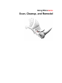
1
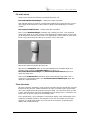
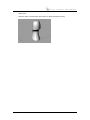
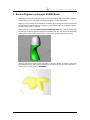
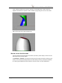
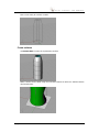
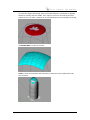
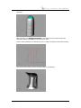
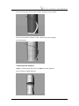
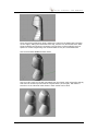
Using Rhinoceros
Scan, Cleanup, and Remodel
S C A N ,
C L E A N U P ,
A N D
R E M O D E L
Copyright © 2006 Robert McNeel & Associates. All rights reserved.
Rhinoceros is a registered trademark and Rhino is a trademark of Robert McNeel &
Associates.
Copyright © 2006 Robert McNeel & Associates.
ii
S C A N ,
C L E A N U P ,
A N D
R E M O D E L
1 Introduction
This document shows how to do two things:
• Bring the meshes into Rhino and clean them up, making them suitable for rapid
prototype (STL) printing as a single, closed mesh. A scan from the NextEngine
Desktop Scanner is used as the example. More information on the NextEngine
scanner can be found at: www.nextengine.com.
• Use the cleaned up mesh as a basis for making a smooth, accurate, NURBS
model, suitable for any down-stream manufacturing process.
Reverse Engineering – A Short Discussion
There is a lot of confusion about scanning. Part of this confusion is from the
misinformation passing between well-intentioned users and part is from the overly
general nature of the questions asked. For our purposes, we will define reverse
engineering as taking an existing object and using some process to make more. The
two primary reasons for doing this are to make duplicates for reproduction and to
make replacement parts.
When making physical duplicate, the goal is to model as accurately as possible,
preserving the odd nature and special features of the object. This might be done for
historical preservation or restoration, to mass-produce a unique object like a special
wood carving, or to model a damaged knee joint for a prosthetic replacement, for
example. The key is preserving the detail and accuracy from the original example.
When creating a new model, working from a typical example, of something that is
worn or damaged, and needs to be replaced, the person doing the work needs to have
a good understanding of the original part and the circumstances of its use. In this
situation, the model will not precisely follow the original, in order to compensate for
the wear and damage to the original. The key is to make an accurate model of what
the original might have looked like before it was worn or damaged.
In both of these cases, it is not possible nor realistic to think that reverse engineered
part will produce an identical replacement. Close inspection and comparison will
always find small differences because of the processes used and decisions made by
the skilled operator.
There are two primary ways to duplicate a part. One is to use a process to make a
mold of the original and make castings using the mold. This process is outside the
scope of this discussion.
The second is to take physical measurements, or through a CMM or scanning process,
and make an electronic model that in turn can be machined, or printed through one of
the many rapid prototyping technologies. Generally speaking, if the part is mechanical
in nature, and direct measurements can be made from the part, it is much faster to
measure the part and model it using modern Computer Aided Design software like
Rhino. If the part it twisty or curvy, it can be very difficult and time consuming to take
direct measurements. Just ask someone that measures clay models of concept or
production automobiles and creates models from the data. This is one example where
scanning can save a great deal of time and capture a great deal of accuracy. When
laser-scanning technology is used, best results are obtained from objects with a light
colored, non-reflective matte finish. Dark, reflective, or fuzzy objects do not lend
themselves to laser scanning. Additionally, scanning tends to "melt" detail. Sharp
edges and creases are rounded over and filled in a little when the mesh facets are fit
to the scanned point data.
Copyright © 2006 Robert McNeel & Associates.
1
S C A N ,
C L E A N U P ,
A N D
R E M O D E L
2 Clean-up for rapid prototype printing
The NextEngine "ScanStudio" software can export to STL, VRML, OBJ, and XYZ point
file formats. Rhino can read all of them. OBJ is the preferred file format.
Set up Rhino display modes
The five default named display settings do not lend themselves to editing dense
meshes. To work with dense meshes, two new display configurations are needed.
Rhino V4 offers this capability to create, name, and save them.
Tools > Options > Appearance > Advanced Settings allows this. Create the first
new named display configuration called Shaded Mesh Editing with the following
settings:
Display Mode Options
Change these settings to create the two new named display configurations. All other
controls should be left at default values.
Name:
Shaded Mesh
Editing
Name:
Wireframe Mesh
Editing
Section
Control
Viewport
settings
Background:
Use Application
Settings
Use Application
Settings
Shading
settings
Shade objects:
On
Off
Flat shading*:
On
N/A
Backface* Settings
Single color for all
backfaces
Use front face
settings
Color:
Cyan
N/A
Show isocurves:
Off
On
Show mesh wires
Off
On
Naked edge* color
usage:
Use single color for
all naked edges
Use single color for
all naked edges
Naked edge color:
Magenta
Magenta
Naked edge
thickness:
2
2
Color reduction %:
20
20
Visibility
Objects Meshes
Mesh Edge
Settings
*Flat shading - disables the automatic display smoothing of meshes.
*Backface – Mesh facets and surfaces have front and back directions. Backfaces are
oriented to be facing the interior of a closed volume.
*Naked edges - are mesh or surfaces edges that are not joined to other mesh or
surfaces edges.
Copyright © 2006 Robert McNeel & Associates.
2
S C A N ,
C L E A N U P ,
A N D
R E M O D E L
Opening the scan
NextEngine is ScanStudio application can export their aligned, trimmed, and blended
meshes in a variety of formats. Rhino can open all of them. The preferred file format is
OBJ.
1
Start a new modeling session in Rhino using the Small objects - Inches
template.
2
Use File > Import, and select the Bottle.OBJ file exported from ScanStudio. It
will come in as 17 different meshes grouped together.
3
Use Rhino transform commands to move and position the grouped meshes into a
logical location for editing over the 0,0 origin. See the Rhino training material
from information on using these transform commands.
4
Right-click the Perspective viewport title and change the display to Shaded
Mesh Editing.
Imported meshes showing "naked" edges in Rhino:
Check the mesh
The individual meshes in the OBJ file were grouped together keep them together.
Ungroup them, and Join the 17 meshes into a single mesh to make them simpler to
work with.
The first order of business is to clear up any easily avoided problems. Rhino has
several commands that are useful for checking and repairing mesh files start with:
CheckMesh - Checks mesh objects for errors and reports problems, which include:
• Degenerate faces - Fix with the CullDegenerateMeshFaces command.
• Zero length edges - Zero-length edges typically are the result of degenerate
faces. Fix with the CullDegenerateMeshFaces command.
• Non-manifold edges - Use the CullDegenerateMeshFaces command and then
fix with the ExtractNonManifoldMeshEdges command.
• Naked edges - Naked edges are allowed, but cause problems with rapid
prototyping. Use the ShowEdges command to help find them or set the display
mode to paint them a different color. Try the FillMeshHole, FillMeshHoles, or
MatchMeshEdge commands to remove naked edges.
Copyright © 2006 Robert McNeel & Associates.
3
S C A N ,
C L E A N U P ,
A N D
R E M O D E L
• Duplicate faces - Fix with the ExtractDuplicateMeshFaces command.
• Faces with reversed normals. Fix with the UnifyMeshNormals command.
• Disjoint pieces - Fix with the SplitDisjointMesh command.
• Unused vertices - Unused vertices do not usually cause a problem, and there
are no commands to for removing them in Rhino.
Specific details on these commands can be found in the Rhino Help file.
CheckMesh reported:
This is a bad mesh.
Here is what is wrong with this mesh:
• Mesh has 11 non-manifold edges.
• Mesh has 6 duplicate faces.
• Skipping face direction check because of positive non manifold edge count.
Important things to consider with this mesh:
• Mesh has 14044 naked edges. Although this does not necessarily mean that the
mesh is bad,
• Naked edges can cause problems if the ultimate goal is STL output.
General information about this mesh:
• Mesh does not have any degenerate faces.
• Mesh does not have any zero length edges.
• Mesh has 88 disjoint pieces.
• Mesh does not have any unused vertices.
ID: 8ba20560-dae9-483a-a801-ea150a8662b5 (49)
Layer name: Default
Render Material:
• source = from obj
• index = 20
Attribute UserData:
• UserData ID: B0EE2168-8EC6-42ed-A962-26DEB8CC8F9A
• Plug-in: Rhino Render
• description: Rhino Renderable Object UserData
• saved in file: no
• copy count: 2
Geometry:
• Valid mesh.
• Open polygon mesh: 229147 vertices, 445784 polygons with normals
• bounding box: (-0.946531,-1.08,-0.0272168) to (1.00295,0.980724,4.7215)
Copyright © 2006 Robert McNeel & Associates.
4
S C A N ,
C L E A N U P ,
A N D
R E M O D E L
Fix mesh errors
These errors indicate the following commands should be run:
ExtractNonManifoldMeshEdges – Delete them after extraction
Non-manifold edges are surface or mesh facets edges that are joined to two or more
other edges at the same time. Rhino does not allow nonmanifold edges in surface
models.
ExtractDuplicateMeshFaces – Delete them after extraction
Next, run the MatchMeshEdge command with a setting of 0.001". This command
moves face edges of an open mesh to meet adjacent face edges exactly so the mesh
will be closed and can take some time to run depending on the number of open mesh
facets. This process may take about 10 minutes. Here is the result:
Most of the seams are joined up but not all.
After this run CheckMesh again. It may find additional non-manifold edges and
duplicate faces created by MatchMeshEdge. If it does, run
ExtractNonManifoldMeshEdges and ExtractDuplicateMeshFaces again and
delete the extra faces.
Next run the FillMeshHoles command. When automatically filling holes it can it
create more nonmanifold edges. Run ExtractNonManifoldMeshEdges again and
delete any extracted faces.
Close the mesh
All of the relatively "automatic" clean-up work has been done but we still are not quite
finished. At this point the model should have an open (not water-tight) "good mesh"
with a few complicated holes that still need to be fixed. The rest of the clean-up work
is more manual and will require a few additional mesh editing tools. To effectively use
these tools, we will be using some new display tools.
In the image below, we've changed to a wire frame display (with naked edges set to
magenta) to simplify selection, and zoomed in on a hole and intend to fix the hole.
However, the small mesh facets on the far side of the mesh are complicating the
display and will affect picking.
Copyright © 2006 Robert McNeel & Associates.
5
S C A N ,
C L E A N U P ,
A N D
R E M O D E L
Use the ClippingPlane command to mask the mesh facets in back.
Since these holes are on the front of the bottle, use the ClippingPlane command in
the Front viewport. By default, the clipping plane is oriented to mask the objects in
front. In this case, we want to mask the objects in back so we will Rotate the clipping
plane 180 degrees.
Here is a view of the Perspective viewport showing the Front viewport clipping
plane:
Here is the result of it in the Front Viewport:
Copyright © 2006 Robert McNeel & Associates.
6
S C A N ,
C L E A N U P ,
A N D
R E M O D E L
Here is a shot of the Front viewport showing the results of using the ClippingPlane.
Now in the front viewport, zoom in on an area with naked magenta edges. The mesh
on the other side of the clipping plane will now not be displayed.
In the above image, notice how some of the naked edges cross over each other?
These are mesh triangles that are complicating the closing of the holes, and the
reason the more automatic commands could not fix the holes for us. Use the
DeleteMeshFaces command to remove the facets that are crossing over other mesh
facets.
Here is the same view with the overlapping mesh facets deleted. See how the hole
border is now clearly shown?
Use FillMeshHole (singular) to close the hole.
Copyright © 2006 Robert McNeel & Associates.
7
S C A N ,
C L E A N U P ,
A N D
R E M O D E L
Here is the result:
Sometimes it is difficult in the faster Wireframe Mesh Editing display, to see what is
really going on over these complicated holes. When that happens, switch over to the
Shaded Mesh Editing display mode. Then the problems will be easier to see.
Here is an example of another hole with mesh facets crossing over it.
Here is the same hole after deleting most of what appeared to be overlapping mesh
faces
Copyright © 2006 Robert McNeel & Associates.
8
S C A N ,
C L E A N U P ,
A N D
R E M O D E L
Well-defined holes like this one are ready for filling. The two naked edges on the right
indicate some facets should be deleted before filling the hole.
Use the same techniques using view clipping planes, deleting misplaced mesh facets,
and filling holes, to work your way around the mesh and fix all of the holes and naked
edges.
Some other commands useful for doing this clean up work are:
PatchSingleFace - Fills a mesh hole with a single mesh face
SplitMeshEdge - Divides a mesh edge to create two or more triangles
SwapMeshEdge - Transposes the corners of mesh triangles that share an edge
When all of the holes are filled and the naked edges dealt with, the mesh will be
closed. The Details button on the Properties dialog box will report:
• Geometry: Valid mesh. Closed polygon mesh.
Additionally, run CheckMesh one more time as a second check:
This is a good mesh.
General information about this mesh:
• Mesh does not have any degenerate faces.
• Mesh does not have any zero length edges.
• Mesh does not have any non manifold edges.
• Mesh does not have any naked edges.
• Mesh does not have any duplicate faces.
• Mesh does not have any faces that could make it better if their directions were
flipped.
• Mesh does not have any disjoint pieces.
• Mesh does not have any unused vertices.
ID: d7fd1a57-4be1-4636-8232-0bd7ffc58fa7 (467784)
Layer name: Default
Render Material:
• source = from obj
• index = 18
Attribute UserData:
• UserData ID: B0EE2168-8EC6-42ed-A962-26DEB8CC8F9A
Plug-in: Rhino Render
description: Rhino Renderable Object UserData
saved in file: no
copy count: 179
Geometry:
Copyright © 2006 Robert McNeel & Associates.
9
S C A N ,
C L E A N U P ,
A N D
R E M O D E L
Valid mesh.
Now the mesh is closed mesh and ready for rapid-prototype printing.
Copyright © 2006 Robert McNeel & Associates.
10
S C A N ,
C L E A N U P ,
A N D
R E M O D E L
2 Reverse Engineer an Accurate NURBS Model
Start with the cleaned-up closed mesh. Technically starting with mesh clean up first is
not necessary, but it will make harvesting complete curves a little easier.
Begin by using a series of commands for breaking up the mesh into logical pieces from
the stand point of Rhino surface modeling. Put the different pieces on different layers
to make them easier to manage.
Experimenting showed that ExtractConnectedMeshFaces with a setting of less than
15 degrees worked to split the bottom of the bottle from the cap. This took advantage
of the greater angle of the mesh facets in the groove between the body and cap.
The next step was to split out the leaf detail on the cap. Sketch an outline curve in the
top viewport and use point-editing techniques to adjust the curves. Then project the
curve onto the mesh, and use MeshSplit.
Copyright © 2006 Robert McNeel & Associates.
11
S C A N ,
C L E A N U P ,
A N D
R E M O D E L
Use a similar procedure to trim the cutaway on the bottle base, except used the
apparent intersection to split the mesh instead of projecting the curve to the mesh.
Split off the top of the cap the same way
Harvest curves from the mesh
Use the surfaces as visual reference and the symmetry of the shape, to draw curves
that capture the primary shape.
The Section or Contour commands can also slice through the mesh to make curves.
These curves would accurately follow the mesh facets, but they would be unsuitable
for making good NURBS surfaces without extensive clean up and simplification.
Copyright © 2006 Robert McNeel & Associates.
12
S C A N ,
C L E A N U P ,
A N D
R E M O D E L
New curves ready for surface creation.
Create surfaces
Use NetworkSrf to make the replacement surface.
Make a surface for the base using the scanned surfaces as reference. Add the bottom
relief details later.
Copyright © 2006 Robert McNeel & Associates.
13
S C A N ,
C L E A N U P ,
A N D
R E M O D E L
To model the slightly domed top, draw curves that follow the centerlines in opposite
directions crossing over the middle. Then copy the curves to the ends of the other
centerline curve to make a network of curves that follows the curved shape of the top.
Use NetworkSrf to make the surface.
Trim the three new surfaces with each other to make the basic replacement body.
Here is before:
Copyright © 2006 Robert McNeel & Associates.
14
S C A N ,
C L E A N U P ,
A N D
R E M O D E L
And after:
After trimming, use ShrinkTrimmedSrf to minimize the extra control within the
trimmed surfaces, and Join the surfaces into a solid.
Use the same techniques of sketching curves to make a surface for the bottle cutaway.
Here is the new surface and the scanned mesh for comparison.
Copyright © 2006 Robert McNeel & Associates.
15
S C A N ,
C L E A N U P ,
A N D
R E M O D E L
The new surface fits well but shows a little undulation near the base.
One way minimize this "flutter" is with a little control point nudging.
This looks better:
Trim and join the surfaces
Trim the surfaces with each other and Join them back together.
Here is what the model looks like:
Copyright © 2006 Robert McNeel & Associates.
16
S C A N ,
C L E A N U P ,
A N D
R E M O D E L
There are still a few details to finish: splitting the cap from the bottle body, blending
out the edges, adding the leaf detail to the cap, and the rim relief detail to the base.
These modeling techniques are commonly used in Rhino surface modeling and not
specific to reverse engineering from scanned data so they are not detailed here.
Here is the finished NURBS surface model.
Here is an STL mesh (on the left) generated from the closed, solid, polysurface side by
side with the cleaned up scan from the original bottle (on the right). Flat shade is
turned on so the individual mesh facets in both models can be seen.
Copyright © 2006 Robert McNeel & Associates.
17
S C A N ,
C L E A N U P ,
A N D
R E M O D E L
Final results and summary
Do not get the impression that one model is any "better" than the other. They are
different, and each is better suited to different situations, needs and requirements.
If the job is to duplicate and original as accurately as possible, capturing unique
details and differences in the object as closely as possible, then scanning and leaving
the data as a mesh is about as good as it can get. Sharp edges and creases in the
original will be rounded a little. The little flaws in your sample (note the rippling effect
in the cap from the threads) will be captured and even the thickness of the paper label
can be seen. A small amount of surface noise or "orange peel" roughness is to be
expected and can be seen in the apparent roughness of the scan. This can be reduced
with the Rhino Smooth command.
If the job is to try to reverse engineer an object from an original example, but also
clean up the data in an attempt to capture the original design, then the extra work of
modeling the part using NURBS surfaces may be worth the effort. Even at that, the
results will not be a perfect replacement of the original because of the assumptions
the Rhino operator made in the reverse engineering process.
Copyright © 2006 Robert McNeel & Associates.
18