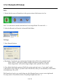
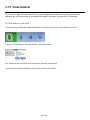
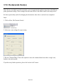
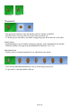
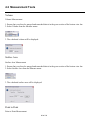
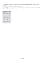
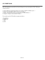
1
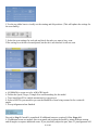
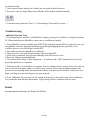
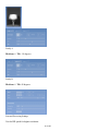
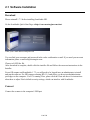
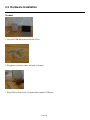
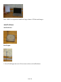
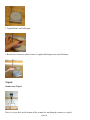
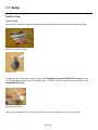
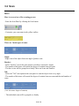
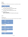
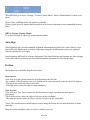
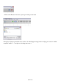
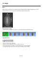
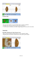
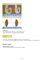
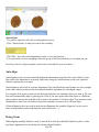
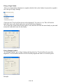
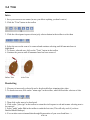
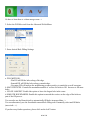
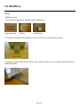
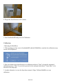
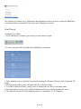
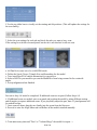
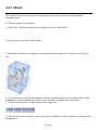
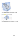
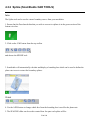
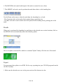
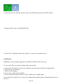
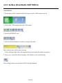
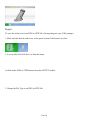
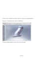
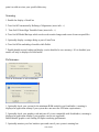
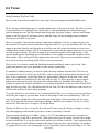
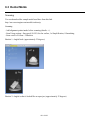
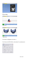
User's Guide: Oct 29, 2009
Additional information online at:
http://support.nextengine.com
Table of Contents
1
What's New...
1.1 HD 1.2.0........................................................................................................................................... 2
1.2 MultiDrive......................................................................................................................................... 3
2
Setup / Installation
2.1 Software Installation......................................................................................................................... 11
2.2 Hardware Installation........................................................................................................................ 17
3
Scan Process
3.1
3.2
3.3
3.4
3.5
3.6
3.7
Setup................................................................................................................................................ 22
Scan ................................................................................................................................................ 24
Align................................................................................................................................................. 29
Trim.................................................................................................................................................. 35
Fuse................................................................................................................................................. 38
HD PRO........................................................................................................................................... 43
Polish................................................................................................................................................ 44
3.7.1 Fill........................................................................................................................................... 44
3.7.2 Buff......................................................................................................................................... 47
3.7.3 Simplify (reduce triangles)...................................................................................................... 49
3.7.4 Remesh (fill holes).................................................................................................................. 51
3.7.5 Clean Defects......................................................................................................................... 53
3.7.6 Re-Generate Scan(s)............................................................................................................. 54
3.8 MultiDrive......................................................................................................................................... 55
3.9 Output............................................................................................................................................... 61
4
Using Scanned Data
4.1 View Controls................................................................................................................................... 63
4.2 Measurement Tools.......................................................................................................................... 66
4.2.1 Point to Point Measurement................................................................................................... 68
4.3 CAD Tools........................................................................................................................................ 69
4.3.1 Orient ..................................................................................................................................... 70
4.3.2 Spline (ScanStudio CAD TOOLS).......................................................................................... 72
4.3.3 Surface (ScanStudio CAD TOOLS)....................................................................................... 76
4.3.4 Compare (ScanStudio CAD TOOLS)..................................................................................... 79
4.4 RapidWorks...................................................................................................................................... 81
4.4.1 Exporting to RapidWorks........................................................................................................ 82
4.4.2 CGI Workflow......................................................................................................................... 84
4.4.3 CAD Workflow........................................................................................................................ 87
4.5 Using in Other Programs.................................................................................................................. 90
4.5.1 AutoDesk ............................................................................................................................... 91
4.5.2 Publishing for Web................................................................................................................. 92
4.5.3 Blender 3D............................................................................................................................. 93
4.5.4
4.5.5
4.5.6
4.5.7
4.5.8
4.5.9
Rhinoceros............................................................................................................................. 94
RapidForm.............................................................................................................................. 95
Geomagic............................................................................................................................... 97
Maya....................................................................................................................................... 98
SolidWorks............................................................................................................................. 99
3D Studio................................................................................................................................ 104
5
Reference
5.1
5.2
5.3
5.4
System Requirements...................................................................................................................... 106
Glossary........................................................................................................................................... 110
Hardware Info................................................................................................................................... 112
Customizing ScanStudio.................................................................................................................. 113
6
Examples
6.1 Skull.................................................................................................................................................. 117
6.2 Faces................................................................................................................................................ 119
6.3 Dental Molds.................................................................................................................................... 121
Chapter 1
What's New...
1 of 126
1.1 HD 1.2.0
2 of 126
1.2 MultiDrive
Setup
MultiDrive Setup
1. Here are the items that are included with the Dual-Axis AutoPostioner
Allen wrench and
L Bracket
AutoPostioner
2. Attach the L Bracket to the MultiDrive with two flat head screws and allen wrench
3. Attach the MultiDrive to the bottom of the scanner and fasten a screw underneath the scanner for
additional stability
3 of 126
4. Plug in the MultiDrive to the scanner
5. Start ScanStudioHD and proceed to Calibration
Calibration
Calibrating the MultiDrive
1. When starting your first scan in ScanStudioHD with the MultiDrive attached, the calibration setup
screen will be displayed.
2. Place the model on the MultiDrive for calibration and press "Start" to begin the automated
calibration process. "Skip" if you wish to proceed to the scan panel and choose "Learn More" to be
directed to this help page. We suggesting using the palm tree included with the MultiDrive.
3. Another alternative is to use the drop down menu of Align, Calibrate MultiDrive to run
calibration.
4 of 126
This function is available for re-calibration when alignment results in an error or when the MultiDrive
was detached and is reattached.
4. Proceed to start scanning your model.
Scan Process
Scanning Your Model
1. After calibration is complete, press the green start button to begin.
2. A new scan panel will be loaded when a MultiDrive is attached.
a. Three families are now available for predefined settings for Rotation, Division, Start Angle and Tile
Angle.
b. Clicking on the family name will enable the tab to edit the settings.
c. To enable or disable a family, simply check or uncheck the box next to the family name.
d. Starting positions can be set for both the initial and tilt axis by moving the slider bar arrow.
e. The start axis has the full 360 rotation and tilt axis is bounded to -35 to 45 degrees.
5 of 126
f. Use the top slider bars to visually set the starting and tilt positions. (This will update the settings for
the scan family)
3. Select the scan settings for each tab and check the tabs you want to have scan.
If the setting for a tab have been adjusted, but the tab is not checked it will not scan.
a. All MultiDrive scans are to be in MACRO mode.
b. Define the Speed, Target, Triangle Size and Smoothing for the model.
c. Turn AutoAlign ON to enable automation for scan process.
4. Select a ROI for your model to prevent the MultiDrive from being scanned in for certain tilt
angles.
5. Accept alignment when finished
Proceed to Step 9 if model is completed. If additional scans are required, follow Steps 6-8.
6. If additional scans are needed, enter scan panel and position the model by using different starting
and tilt angles to capture additional scans. If you physically adjust the part, then a 3 pin alignment will
6 of 126
be needed to align.
7. Once scans are done, drag the new family into the green from the blue area.
8. Proceed to enter the Align Menu and run Refine on the models attached manually.
9. Trim unnecessary data and "Fuse" or "Volume Merge" the model for export: ->
Troubleshooting
Additional Tips and Tools
1. Switching between AutoDrive and MultiDrive Simply just plug in a AutoDrive to display the proper
UI. When reattaching the MultiDrive, make sure to recalibrate as needed.
2. Using MultiDrive with AutoAlign turned OFF With AutoAlign turned OFF for a dual axis scan, you
can manually refine the alignment and attach scans through dragging into the green.Here is the
workflow process when AutoAlign is turned OFF
a. First make sure that the MultiDrive is calibrated.
b. Then proceed to scan with defined settings with AutoAlign OFF.
c. After scan is completed, drag all scans manually from the blue area to the
d. Enter the Align menu and run Refine.
e. Use the drop down Align, Global Alignment -> if needed use the "ASK" button below if you have
any further questions or comments.
3. When more than 3 Scan families are required. You can add more than 3 scans/sessions. Just click on
scan to enter the scan panel, and you can add 3 more sessions. These scans should auto align to the
previous scans assuming all the movement and rotations were done by the turntable. If they don't autoalign , just drag the scans into the green (no pins required)
4. Force Calibration. If your scans are not coming in aligned, you may need to run a force calibration.
You can do this from the drop down menu , Align, then go down to calibrate-dual-axis item.
Dental
Recommended Scan Settings for Dental Cast Models
7 of 126
Family A
Divisions: 6 Tilt: -10 degrees
Family B
Divisions: 6 Tilt: 40 degrees
Scan and Processing Settings
Use the HD speed for higher resolution
8 of 126
9 of 126
Chapter 2
Setup / Installation
10 of 126
2.1 Software Installation
Download
Please uninstall 1.7.3 before installing ScanStudio HD.
Go the ScanStudio Quick Start Page at http://www.nextengine.com/start
Enter your e-mail address and password
You can find your username and password in the order confirmation e-mail. If you need your account
information please e-mail [email protected]
Choose to SAVE the file.
After download is complete, double click the installer file and follow the onscreen instructions in the
Installer.
For an SD scanner and ScanStudio 1.7.3 you will need to be logged in as an administrator to install
and run the software. For HD scanners running HD 1.1.0 and newer you do not need administrator
privledges on the computer. For PC's running Vista, please click the Vista tab above for instructions
about how to adjust Vista's default security settings, which can interfere with ScanStudio.
Connect
Connect the scanner to the computer's USB port
11 of 126
A window will appear alerting you that new hardware has been detected.
Select "Yes" and click Next
Select "Install the software automatically (Recommended)" and click Next
When the wizard has completed the installation click Finish
12 of 126
Online
If your computer is connected to the internet it should automatically detect your computer and validate
your ScanStudio license.
- Go to Help, About ScanStudio to see which version of ScanStudio you are running
- Click on Support and go to My Software to see your license status.
Offline
You do not need an Internet connection to use ScanStudio.
- If your computer is offline you will see this screen in the NextWiki
- Please go to this link http://support.nextengine.com/license/setup and enter in the requested machine
information.
13 of 126
- Your license will be e-mailed to you.
- Save the license file on your computer.
- Click the license file to launch ScanStudio.
License
ScanStudio Core or HD Licensing:
Core or HD can be installed on multiple computers.
If your scanner says HD on the front you will want to run HD, if not run Core.
ScanStudio CAD Tools and HD Pro Licensing:
14 of 126
CAD Tools is assigned to a single username and can only be used on one computer per license.
To transfer the license for CAD Tools, Rapidworks or HD Pro from one computer to another, please
note the following procedure:
1. Click on Support inside of the application.
2. Go to My Software
3. To activate, click where it says "OFF" and then it will say "activating" followed by "ON"
4. You need to turn the software "OFF" on the old computer before activating it on a new machine.
15 of 126
If you have a question about your license please click ASK and someone from technical support will
help you.
16 of 126
2.2 Hardware Installation
Scanner
1. Get your USB and power cords out of box
2. Plug power cord into outlet and back of scanner
3. Plug USB cord into back of scanner and computer USB port
17 of 126
Note: USB 2.0 is required to handle the large volume of 3D data and images.
AutoPositioner
AutoPositioner
PartGripper
1. Screw PartGripper into one of four corner sockets on AutoPositioner
18 of 126
2. Tighten Platter on PartGripper
3. Rotate Post clockwise (about 6 turns) to tighten PartGripper into AutoPositioner
Tripod
Scanner and Tripod
There is a screw hole on the bottom of the scanner for attaching the scanner to a tripod
19 of 126
Next Step: Download and install ScanStudio -> or if already installed start your first scan
20 of 126
Chapter 3
Scan Process
21 of 126
3.1 Setup
Surface Prep
Surface Prep
Prepare dark, shiny or transparent objects using included tools to help the lasers capture the data.
Paint Pens: Washes off most
Powder: Talc
Testing has also shown that a spray powder like Magnaflux Spotcheck SKD-S2 Developer works
well for prepping objects prior to scanning. Here is a link to the site where you can purchase some.
Magnaflux Buy Page
Magnaflux Spotcheck
Other spray alternatives such as foot powder spray or white hairspray can be used as well:
22 of 126
Foot powder spray from
White Hairspray
White Hairspray Buy Page
Alignment Prep
Alignment Prep
It may be helpful prior to scanning to make alignment marks using the alignment pen. These marks
will make it easier to place pins and identify locations on the object.
23 of 126
3.2 Scan
Intro
Here is an overview of the scanning process
- Enter the Scan Panel by clicking the Scan button
- Customize your scan name in the yellow toolbar
There are 3 main types of scans:
Single:
-Single scan of the object from one angle. Quickest scan.
Bracket:
- Select "bracket" scan in the scan panel to scan three consecutive angles.
- The number of divisions will control the degree of rotation between scans
- The three scans will be grouped as a family. More on Scans and Families
360:
- Select the "360" scan option in the scan panel to scan the object from every angle.
- The number of divisions will control the degree of rotation between scans and the total number of
scans:
(360 / divisions= degree of rotation)
- The individual scans will be grouped as a family.
24 of 126
Speed
Precision:
Choose MACRO or WIDE distance based on object size and desired resolution
Macro = 0.005" accuracy, 3x5" field of view
Place object 6.5 inches from the front of the scanner
Wide = 0.015" accuracy, 10x13" field of view
Place object 17 inches from the front of the scanner
Extended Wide Mode
Available with HD PRO
Objects can be placed up to 32" from the face of the scanner
Speed:
ScanStudio Core
Choose Standard, Quick or Fine scan speed based on desired scan time and quality
ScanStudio HD
ScanStudio HD PRO
25 of 126
-With HD PRO go to Scan - Settings - Texture Capture Mode - choose Monochrome for faster scan
speed.
Choose Fine or HD Speed for the greatest resolution.
Choose Quick Speed to capture data the quickest with lowest resolution (not recommended for most
parts).
HD Pro Texture Capture Modes
Go to Scan/Settings to adjust the texture capture modes.
AutoAlign
AutoAlignment uses previous turntable alignment information to position the scans relatively close
then refines the alignment to accurately align scans using the AutoPositioner as they are captured,
without requiring any user input.
AutoAlignment will result in accurate alignments if the AutoPositioner and Scanner are close enough
to the same relative position as the last manual turntable alignment (for each depth range).
Position
Orient object in viewfinder using Rotate buttons
Step Arrows:
-One click on a Step Arrow rotates the AutoPositioner one division.
-For example, if the divisions is set at 4, clicking on the step button will rotate the object 90 degrees.
- The left arrow rotates the object clockwise.
- The right arrow rotates the object counterclockwise
Turn Arrows:
-One click on a Turn Arrow rotates the AutoPositioner a single increment for more precice
positioning.
-The left turn arrow rotates the object clockwise in the viewfinder.
-The right turn arrow rotates the object counter clockwise in the viewfinder
*Note: The AutoPositioner should only be rotated using the Rotate Arrows and should not be done
manually.
Drag the cursor around the object to select a smaller scan area
26 of 126
Run
Starting/Stopping a Scan:
- Click the Start button to run the scan
- Click the Stop button to stop the scan
During a Scan:
- Explore the Support System
- Edit completed individual scans of a bracket or 360 scan ->.
After a Scan:
- Click on the Close button to close a scan before opening a new one
27 of 126
- Click on the Browse button to open a previously saved scan
Next Step: Remove unwanted areas such as the PartGripper using Trim or Align your scans to make a
complete model -> . For tips on viewing your scan ->
28 of 126
3.3 Align
Intro
Note: It may be helpful prior to scanning to make alignment marks using the alignment pen. These
marks will make it easier to place pins and identify locations on the object.
Selecting Scans to Align
- Double click on thumbnail of a family to separate the family into individual scans
Alignment Screen
- Click on Align to enter alignment
- When you enter Alignment, you'll see a split screen view
- The left side shows an assembly of scans/families that are already aligned
- The right side shows the next piece that you're attaching to that assembly
29 of 126
Thumbnail Bar
- The green side contains scans and families that are already assembled
- The blue side is for pieces that aren't part of the assembly yet
- To break apart or assemble your model, simply drag parts from one side to the other
Turntable
Turntable Alignment for 360 or Bracket Scans
- Place 1 pin on a common location between 2 scans within the family.
- Drag the pin to the location or double click on the point to place the pin.
30 of 126
Attach Scans
- The yellow status bar will walk you through the process
- Click "Attach Scans" to add your scan to the assembly
- Click File > Save after each alignment in order to save pin locations
- You can detach a scan by dragging it from the green to the blue and then you can adjust the pin.
Multiple Families
Aligning Multiple Families
- Place 3 pins on common locations between the 2 families
31 of 126
Attach Scans
- The yellow status bar will walk you through the process
- Click "Attach Scans" to add your scan to the assembly
- Click File > Save after each alignment in order to save pin locations
- You can detach a scan by dragging it from the green to the blue and then you can adjust the pin.
Next Step: Once it's all put together, learn how to trim and fuse your scan data ->
AutoAlign
AutoAlignment uses previous turntable alignment information to position the scans relatively close
then refines the alignment to accurately align scans using the AutoPositioner as they are captured,
without requiring any user input.
AutoAlignment will result in accurate alignments if the AutoPositioner and Scanner are close enough
to the same relative position as the last manual turntable alignment (for each depth range).
For example: Start up the scanner for the first time and place the turntable where you want it. Do your
first scan and manually align by placing pins. Then if you scan again either that object or a different
object without moving the turntable with respect to the scanner it will auto-align. You can then restart
ScanStudio or start a new scan and as long as the turntable is not moved it will auto-align.
If AutoAlignment does not result in an accurate alignment, the standard Align tool can be used to
place correspondence points and align the scans (more info: ->).
Fixing Scans
When aligning multiple families it may be beneficial to lock the individual families in place so that
any future alignment does not disrupt the already aligned families.
32 of 126
Fixing a Single Family
-After your single family alignment is complete (double click on the family if you need to expand it
out), then go to Align, Settings.
-Check the box "Fixed (will not be moved by alignment)" for scans A1-An. This will lock the
individual scans in the family and not be moved with future alignment.
-If you check the Fixed button for the Family A tab, then this will lock the entire family in place and
not just the individual scans for that family.
Fixing Multiple Families
-For multiple families, go to Align, Settings and check the box "Fixed (will not be moved by
alignment)" for the families that have been sucessfully aligned and wish to be locked in place.
Example:
33 of 126
1. Attach Family A to Family B (both families are not fixed)
2. Go to Align, Settings and check "Fixed" for Family A and Family B (They are now locked in
position)
3. Proceed to attach Family C to A and B.
4. After C is sucessfully aligned, then go to Align, Settings and fix Family C
5. Repeat for any additional family attached.
Advanced Settings
If you go to Edit> Preferences you can access the advanced alignment settings.
34 of 126
3.4 Trim
Intro
1. Save your scan as a new name (in case you delete anything you don't want to)
2. Click the "Trim" button in the toolbar
3. Click the cirlce/square/square selector/poly selector button in the toolbar to select data
4. Select the area on the scan to be removed and continue selecting until all unwanted area is
highlighted
5. To remove selected area, click on the "Trim" button in the toolbar
6. Continue the process until all unwanted area has been removed
Before Trim
After Trim
Deselecting
1. If an area is incorrectly selected it can be deselected before trimming takes place.
2. To deselect an area, click on the "minus sign" in the toolbar, which will turn the selectors to blue
3. Then click on the area to be deselected.
4. Click on the "plus sign" in the toolbar to return the circle/square to red and resume selecting area to
be removed
5. Select "undo" under Edit in the toolbar to undo the last trim. (This will only work if you have
Enabled Model Backups)
6. You can also restore trimmed data through Regeneration of your scan found here: ->
35 of 126
Navigating
1. Click on the "pointer button" before zooming or repositioning the object
2. Drag object up/down while right clicking to zoom.
3. Drag the object while holding down both mouse buttons to pan ->.
4. Hold down center scroll to rotate object without selecting any areas.
When to Trim
1. You can trim completed individual scans of 360/bracket scans while other scans are finishing.
2. Before alignment you should not trim away parts of the object, only parts of the PartGripper.
3. After alignment you can trim overlapping data to improve fusing/merging.
4. Double click on the aligned family and drag the scan to be trimmed into the blue thumbnail bar
Next Step: Fuse your scans to remove any remaining overlap -> or align your scans if needed ->
AutoTrim
Auto-trimming automatically detects and removes data that was captured at a steep angle relative to
the line of sight of the scanner. This can be useful in removing data that may negatively affect
alignment or blending.
Auto-trimming is available under the Polish menu and should be run before aligning, fusing or
merging multiple scans together.
With this option selected you can choose the angle for trimming.
36 of 126
If you have any further questions, please click on the Ask? button.
37 of 126
3.5 Fuse
Intro
The Fuse tool Volume Merges, Remeshes, Fills Holes and Simplifies your aligned scan data.
1. Use Aligned Data
Ensure that the data that you would like to fuse is aligned in the green section of the bottom view
bar:
2. Click Fuse
3. Set Simplification Level
- Enter the desired deviation tolerance for any mesh simplification (decimation)
- 0.00" simplification will not simplify the data
- Increasing the simplification will simplify your model and make the file size smaller.
- It will perform intelligent simplification, which keeps more points in detailed areas and fewer points
in larger planes.
Settings
4. Choose the Settings
38 of 126
- The Hole Filling Slider controls the max. circumference size of holes to fil.
- Control how much blending of the textures to perform (to account for brightness variations):
- Resolution Ratio determines the new average vertice length in relationship to the current length.
- Values less than 1 will decrease your triangle size. Values greater than 1 will increase your triangle
size.
- It is best to keep this at the default of 0.9.
5. Click Fuse
6. Fused Results
The fused results will appear as a new
Volume Merge
The Volume Merge tool eliminates the overlap from multiple scans and merges them into a single
mesh.
Volume Merge can be used in place of Fuse if you do not wish to Remesh or Hole Fill your scans.
To Merge multiple scans into a single mesh:
39 of 126
1. Ensure that the scans to merge are in the green section of the bottom view bar.
2.Select Merge Scans from the Fuse Menu
3. Choose the Resolution Ratio:
- Controls the size and amount of triangles that will be in the merged result.
- It is best to keep it at the default of 0.9.
- Values from 0-1 will result in smaller triangles than those presently in the scan.
- Values larger than 1 will result in larger triangles with a possible loss of detail.
4. A new family is created with the merged results
The Merge process will not automatically fill holes in the mesh where there is no scan data.
You can use the Remesh option after a Merge to create a water-tight mesh (more info: ->).
Large Models
If your model contains more than 1.5 million points you may have to use an alternate method for
Fusing.
1. Check the number of points in your attached data.
40 of 126
2. If your model did not fuse/merge previously you can check to see how many points are in the
attached data. This will help you judge in the future how many points your computer can fuse at
once.
Method 1: Regenerate Data
1. Regenerate your data a higher simplification level.
See next section for instructions for regenerating.
Method 2: Multi-Merge
1. Divide your scans in subgroups (only have one family/group of scans in the green section at a
time)
2. Volume Merge one family at a time
3. Align Merged families together
4. Trim away overlapping areas
5. Perform a final Volume Merge on all the aligned and merged familes
41 of 126
6. Remesh scans to scans to fill holes (optional) (see this link for more on Remesh ->)
Regenerate
Since the raw scan data is saved at scan-time, you can regenerate the points at any time with different
point-generation settings. These settings have the same effect as the sliders on the scan setup screen.
Re-Gen is particularly useful for changing the triangle size (simplification value) after a scan has been
completed.
Steps:
1. Click on Fuse, Re-Generate Scan(s)
2. Select new scan settings for reprocessing
3. Restore Trimmed Data: Choose this option to restore the trimmed data from either a single scan,
family or the entire model.
42 of 126
3.6 HD PRO
To purchase the HD PRO license visit the buy page here.
This software requires an HD capable scanner. For more information click the ASK button
below.
4x Data Capture
HD scan speed allows for a maximum point cloud resolution of .0025", thereby capable of capturing
finer details and smaller objects.
Extended Wide Mode Scanning
In the scan panel select Extended mode ito increase the depth range to 30 inches from the scanner.
The maximum field of view in Extended mode is 16 x 20". There will be a degradation in the accuracy
of the scan results at these distances, it is suggested that you scan white objects for best results.
Faster Laser Scan Time
With HD PRO activated the laser scan time is nearly twice as fast.
Activating HD PRO
To activate HD PRO click on Help>My Software and activate on the My Software page.
43 of 126
3.7.1 Polish: Fill
Intro
HOW TO USE THE FILL TOOL:<B/>
1. Enter the Polish panel:
and select the Fill tool:
ScanStudio will automatically detect holes in the model and display their boundaries:
Note*: Please make sure that when using the Fill tool, you are working with a fused, merged or a
single scan model.
2. Use the selector tools to select the holes that you would like to fill:<B/>
Mesh Mode
44 of 126
Solid Mode
3. When you finish your selection(s), select the Fill button to permanantly commit these triangles into
your model:<B/>
Before Fill
After Fill
Auto Fill Holes
To have ScanStudio automatically fill holes in the scan data:
1. Ensure that the data that you would like to fill holes is a volume merged model in the green section
of the bottom view bar:
45 of 126
Go here to learn how to volume merge scans: ->
2. Select the Fill Holes tool from the Advanced Polish Menu:
3. Enter desired Hole Filling Settings
a. FILL METHOD:
- Flat Fill will fill the holes along a flat edge.
- Smooth Fill will fill the holes along a smooth edge.
- Curvature Fill will analyze the neighboring geometry and try to match the overall curvature.
b. MAX VERTICES: Controls the maximum number of vertices for holes to fill. Increase to fill more
holes.
c. LEAVE LARGEST: Enable this option to leave the largest hole in the scans.
d. SMOOTH BOUNDARIES: Enable this option to smooth the vertices on the edge of the holes as
part of the fill process.
You can also use the Remesh tool to automatically fill holes in merged data: ->
You can alternatively use the ScanStudio manual hole filling tool to manually select and fill holes
(more info: ->).
If you have any further questions, please click on the Ask? button.
46 of 126
3.7.2 Buff
Intro
1. Click on the Polish tool:
Then click on the Buff tool:
Note*: When buffing, please make sure that the model is a fused or merged model.
2. Select localized data to smooth or all for the entire mesh:
Settings
3. Enter the desired buff options:
47 of 126
a. Buff Method: Laplacian and Loop are two different smoothing methods. The Curvature option can
be used for curvature based smoothing.
b. Buff Weight: Increase to run a higher level of smoothing (when the Loop method is used, the
number of iterations is all that needs to be specified, the smoothing weight has no impact).
c. Deviation Tolerance: Optionally enter the allowable deviation for the smoothing.
d. Max Iterations: Increase to run more iterations of smoothing and therefore reduce more noise.
e. Smooth Boundaries: Enable this option to smooth vertices around the edges of holes.
f. Preserve Sharp Edges Enable this option to try and retain sharp edge detail.
Results
Before
After
If you have any further questions, please click on the Ask? button.
48 of 126
3.7.3 Simplify (reduce triangles)
Note*: When using the Simplify tool, please make sure that you are working on a fused or merged
model. Simplifying prior to fusing/merging will create non-uniform mesh and cause the fuse to fail.
Please regenerate scans if you need to decrease model size before fusing (more info ->).
To simplify your scan(s):
1. Click on the Polish tool:
2. Click on the Simplify tool:
3. Select the local data to simplify or select all:
4. Choose the desired simplification tolerance from the top menu bar slider:
Before Simplify
49 of 126
After Simplify
If you have further questions on the simplify tool, please click on the Ask? button.
50 of 126
3.7.4 Remesh (fill holes)
Intro
1. Ensure that the scans to Remesh are in the green section of the bottom view bar
Note*: It is advised to remesh scans that have been merged/fused. For more info: ->.
2. Select the Remesh tool from the Advanced Polish Menu:
Settings
3. Enter Remesh Options:
a. Resolution: Controls the size and amount of triangles that will be in the remeshed result.
Values from 0-1 will result in smaller triangles than those presently in the scan.
Values larger than 1 will result in larger triangles with a possible loss of detail.
b. Close Mesh: Enable this option to fill all holes in the mesh and create a "water-tight" model.
c. Keep Holes Larger Than: If you don't want to fill all holes, then you can manaully set which holes
of circumference size to fill.
The Remesh tool can be very useful when run after Merging Scans to create a water-tight mesh.
You may need to Clean Defects before 3D printing though (more info: ->)
51 of 126
If you have any further questions, please click on the Ask? button.
52 of 126
3.7.5 Clean Defects
Clean Defects should be run at the end of your polishing process and can be used to automatically
eliminate any self intersecting or non-manifold triangles to prepare your mesh for 3D printing.
To Clean Defects in your mesh:
1. Ensure that your Merged and Remeshed data is in the green section of the bottom view bar.
2. Select "Clean Defects" from the Polish - Advanced menu.
Any defects in the mesh will be automatically detected and cleaned.
If you have any further questions, please click on the Ask? button.
53 of 126
3.7.6 Re-Generate Scan(s)
Since the raw scan data is saved at scan-time, you can regenerate the points at any time with different
point-generation settings. These settings have the same effect as the sliders on the scan setup screen.
Re-Gen is particularly useful for changing the decimation value after a scan has been completed.
Steps:
1. Click on Fuse, Re-Generate Scan(s)
2. Select new scan settings for reprocessing
3. Restore Trimmed Data: Choose this option to restore the trimmed data from either a single scan,
family or the entire model.
If you have any further questions, please click on the Ask? button.
54 of 126
3.8 MultiDrive
Setup
MultiDrive Setup
1. Here are the items that are included with the MultiDrive
Allen wrench and
L Bracket
AutoPostioner
2. Attach the L Bracket to the MultiDrive with two flat head screws and allen wrench
3. Attach the AutoPostioner to the bottom of the scanner and fasten a screw underneath the scanner for
additional stability
55 of 126
4. Plug in the AutoPostioner to the scanner
5. Start ScanStudioHD and proceed to Calibration
Calibration
Calibrating the MultiDrive
1. When starting your first scan in ScanStudioHD with the DMultiDrive attached, the calibration setup
screen will be displayed.
2. Place the model on the AutoPostioner for calibration and press "Start" to begin the automated
calibration process. "Skip" if you wish to proceed to the scan panel and choose "Learn More" to be
directed to this help page.
3. Another alternative is to use the drop down menu of Align, Calibrate MultiDrive to run
calibration.
56 of 126
This function is available for re-calibration when alignment results in an error or when the MultiDrive
was detached and is reattached.4. Proceed to start scanning your model.
Scan Process
Scanning Your Model
1. After calibration is complete, press the green start button to begin.
2. A new scan panel will be loaded when a MultiDrive is attached.
a. Three families are now available for predefined settings for Rotation, Division, Start Angle and Tile
Angle.
b. Clicking on the family name will enable the tab to edit the settings.
c. To enable or disable a family, simply check or uncheck the box next to the family name.
d. Starting positions can be set for both the initial and tilt axis by moving the slider bar arrow.
e. The start axis has the full 360 rotation and tilt axis is bounded to -35 to 45 degrees.
57 of 126
f. Use the top slider bars to visually set the starting and tilt positions. (This will update the settings for
the scan family)
3. Select the scan settings for each tab and check the tabs you want to have scan.
If the setting for a tab have been adjusted, but the tab is not checked it will not scan.
a. All Dual Axis scans are to be in MACRO mode.
b. Define the Speed, Target, Triangle Size and Smoothing for the model.
c. Turn AutoAlign ON to enable automation for scan process.
4. Select a ROI for your model to prevent the MultiDrive from being scanned in for certain tilt
angles.
5. Accept alignment when finished
Proceed to Step 9 if model is completed. If additional scans are required, follow Steps 6-8.
6. If additional scans are needed, enter scan panel and position the model by using different starting
and tilt angles to capture additional scans. If you physically adjust the part, then a 3 pin alignment will
be needed to align.
7. Once scans are done, drag the new family into the green from the blue area.
8. Proceed to enter the Align Menu and run Refine on the models attached manually.
9. Trim unnecessary data and "Fuse" or "Volume Merge" the model for export: ->
58 of 126
Troubleshooting
Additional Tips and Tools
1. Switching between AutoDrive and MultiDrive just plug in a AutoDrive to display the proper UI.
When reattaching the MultiDrive, make sure to recalibrate as needed.
2. Using MultiDrive with AutoAlign turned OFFWith AutoAlign turned OFF for a dual axis scan, you
can manually refine the alignment and attach scans through dragging into the green.Here is the
workflow process when AutoAlign is turned OFF
a. First make sure that the MultiDrive is calibrated.
b. Then proceed to scan with defined settings with AutoAlign OFF.
c. After scan is completed, drag all scans manually from the blue area to the
d. Enter the Align menu and run Refine.
e. Use the drop down Align, Global Alignment -> if needed use the "ASK" button below if you have
any further questions or comments.
3. When more than 3 Scan families are required. You can add more than 3 scans/sessions. Just click on
scan to enter the scan panel, and you can add 3 more sessions. These scans should auto align to the
previous scans assuming all the movement and rotations were done by the turntable. If they don't autoalign , just drag the scans into the green (no pins required)
Dental
Recommended Scan Settings for Dental Cast Models
Family A
Divisions: 6 Tilt: -10 degrees
59 of 126
Family B
Divisions: 6 Tilt: 40 degrees
Scan and Processing Settings
Use the HD speed for higher resolution
60 of 126
3.9 Output
61 of 126
Chapter 4
Using Scanned Data
62 of 126
4.1 View Controls
Move
After a scan is complete it will appear in the workspace (grid area) and in thumbnail bar at the bottom.
There are different viewing modes as well as ways to zoom and move your scan.
How to move your model:
- Rotate: hold down the left mouse button and drag
- Zoom: hold down right mouse button and drag up/down (zooms to where you click)
- Pan: hold down the right and left mouse buttons and drag
While in the Trim tool you may click center mouse button (scroll wheel) to rotate model without
changing selector tool.
Mode
Mode: Click a Mode button located in the bottom of the thumbnail bar to change the view.
Texture
Solid
Mesh
Point
63 of 126
Zoom:
Zoom:
If you are unable to view the Texture mode make sure you have textures turned on under EditPreferences:
By turning off textures you can reduce memory usage in large models.
Types
There are 3 main types of scans:
Single:
-Single scan of the object from one angle. Quickest scan.
Bracket:
- Select "bracket" scan in the scan panel to scan three consecutive angles.
- The number of divisions will control the degree of rotation between scans
- The three scans will be grouped as a family.
360:
- Select the "360" scan option in the scan panel to scan the object from every angle.
- The number of divisions will control the degree of rotation between scans and the total number of
scans:
(360 / divisions= degree of rotation)
- The individual scans will be grouped as a family.
64 of 126
360 Family
Bracket
Thumbnails
- The green side contains scans and families that are already assembled
- The blue side is for pieces that aren't part of the assembly yet
- To break apart or assemble your model, simply drag parts from one side to the other
Family Scans
- Each individual scan of a family will appear together, with a thumbnail at the bottom
- Different families will appear in the thumbnail bar labeled A, B, C, etc.
Individual Scans
- Double click on a family thumbnail to see individual scans inside
- Click on any individual thumbnail to view it in the larger grid screen
- To get back to viewing families click up
65 of 126
4.2 Measurement Tools
Volume
Volume Measurement
1. Ensure that your fused or merged and remeshed data is in the green section of the bottom view bar.
2. Select Volume from the Measure menu:
3. The calculated volume will be displayed:
Surface Area
Surface Area Measurement
1. Ensure that your fused or merged and remeshed data is in the green section of the bottom view bar.
2. Select Surface Area from the Measure menu:
3. The calculated surface area will be displayed:
Point to Point
Point to Point Measurement
66 of 126
1. To measure a distance on a scan you can click on one point then press the letter "i" on your
keyboard.
2. This will give you the coordinates of that point.
3. Then do the same at your second point and it will give you the new coordinates along with the
distance to the previous point.
67 of 126
4.2.1 Point to Point Measurement
To measure a distance on a scan you can click on one point then press the letter "i" . This will give you
the coordinates of that point. Then do the same at your second point and it will give you the new
coordinates along with the distance to the previous point.
68 of 126
4.3 CAD Tools
The CAD toolbar has a powerful set of tools to help you use your scan data for CAD, CAM, and
Analysis projects:
1. Orient: Define the origin and position your scan data in global coordinate space: ->
2. Spline: Extract Boundary Splines from your scan data: ->
3. Surface: Automatically convert your scan data to NURBS Surfaces: ->
4. Compare: Compare scan data and CAD data: ->
You can also use the CAD toolbar to output your data to:
1. RapidWorks
2. SolidWorks
3. IGES
4. STEP
69 of 126
4.3.1 Orient
The Orient tool can be used to define an origin and Orient your scan data in a defined global
coordinate space.
To Globally Orient your scan data:
1. Click on the CAD button from the top toolbar to enter the CAD toolbar:
2. Select Orient to enter the Orient toolbar:
3. ScanStudio will show a bounding box representation of the common view planes (top, left, front,
etc.):
4. You can choose to rotate the bounding box and the scan data together, the scan data relative to the
bounding box or the bounding box relative to the scan data by toggling the rotate buttons.
5. Use the constrain buttons to limit rotations on a single axis.
6. Click the base button and place 3 pins on the object to define one of the common view planes of the
bounding box:
70 of 126
7. Click on the origin button and place 1 pin to define the origin.
Notes: Mesh scan data can be globally oriented, but CAD data cannot.
71 of 126
4.3.2 Spline (ScanStudio CAD TOOLS)
Intro
The Spline tool can be used to extract boundary curves from your mesh data.
1. Ensure that the Fused mesh data that you wish to convert to splines is in the green section of the
bottom view bar.
2. Click on the CAD button from the top toolbar
and choose the SPLINE tool:
3. ScanStudio will automatically calculate and display a bounding box which can be used to define the
plane cuts to use to extract the boundary splines:
Orient
4. Use the AXIS button to change which face from the bounding box is used for the plane cuts:
5. The SPACING slider can be used to control how far apart each spline will be:
72 of 126
6. The BOUNDS tool controls which part of the mesh to extract the curves from:
7. The ORIENT tool can be used to position the mesh data relative to the bounding box:
Use the Rotate tools to move either the mesh data, the bounding box, or both:
- The Constrain tools can be used to limit rotation along a particular axis:
- The Base tool can be used to define one of the planes in the bounding box by placing pins on the
mesh
Results
When you've positioned the bounding box and planes to the desired cross section locations, click on
the SPLINE tool to automatically extract the boundary splines.
The set of splines created will be added to a common "Spline" family off of the root of the model.
Export
You can export these splines to an IGES file for easy exporting into your 3D CAD program from the
OUTPUT toolbar:
1. Make sure the desired curves are in the green section of the bottom view bar
73 of 126
2. Select File-Save As from the menu or click on the IGES button from the OUPUT toolbar:
3. Change the File Type to an IGES/STEP file
4. Check "Save "Finished" Scans Only (Green)" to only save the attached curves
SolidWorks
SolidWorks converts Splines imported via an IGES or STEP file into 3D curves.
To convert the 3D curves back to splines with control points:
1. Open up the 3D sketch or create a new sketch if you do not want to delete the imported data.
2. Select the curves of interest
3. Select Convert Entities
4. Go to: tools> spline tools> fit spline
5. Select the generated spline and go to: tools> spline tools> simplify spline
If you only select a single curve, step 4 can be skipped and simplify spline will automatically convert
the curve.
74 of 126
The imported curve geometry will be modified for some spline conversions. Therefore, it is best to
always create a new 3D sketch and retain the original data.
Control points can be moved by dragging or modifying x-y-z positions found in the parameters
window.
75 of 126
4.3.3 Surface (ScanStudio CAD TOOLS)
AutoSurface
1. Ensure that you have merged results in the green section of the bottom view bar:
2. Click on the CAD button to enter the CAD toolbar:
3. Select the SURFACE tool:
3. Select the desired number of surfaces to wrap to the mesh:
More surfaces may result in more accuracy.
If the resulting surfaces have missing data then try increasing the number of surfaces.
4. Once you've entered the desired settings, click Surface to run AutoSurfacing:
The resulting surfaces are stored in the SCN file and displayed:
76 of 126
Export
To save the surfaces out to an IGES or STEP file (for importing into your CAD package):
1. Make sure the desired surfaces are in the green section of the bottom view bar:
2. You can also select File-Save As from the menu:
or click on the IGES or STEP buttons from the OUTPUT toolbar:
3. Change the File Type to an IGES or STEP file:
77 of 126
4. Check "Save "Finished" Scans Only (Green)" to only save the attached surfaces
Example of AutoSurface Result inside of SolidWorks:
If you have further questions, please click on the Ask? button.
78 of 126
4.3.4 Compare (ScanStudio CAD TOOLS)
To compare your scan data to reference geometry:
1. Click the CAD button from the top toolbar:
2. Click the Compare button:
3. Browse to open reference CAD geometry from an IGES or STEP file if it has not already been
imported or generated from an AutoSurface
4. Align the reference data to the scan data if necessary
- You can drag all of the data to compare into the green section of the bottom view bar to view it
together and verify that it is aligned.
5. Select the desired reference entity from the blue section of the bottom view bar
6. The yellow status area will identify what is selected for comparing
7. The color coded tolerance scale allows you to control how the deviation is visualized
8. The knob to the right of the tolerance bar controls the deviation map's scale
9. Click compare to run the comparison
The selected reference entity in the blue will be compared against the scan data in the green section of
the bottom view bar. The results will be color coded and mapped to the scan data in the green when
79 of 126
viewed in texture mode in the Compare tool:
Notes:
- The Deviation Map is only displayed when viewing the scan data in the texture rendering mode.
- The Compare tool does not support CAD to CAD comparisons.
- If you globally orient a model it will only affect the mesh data that you are orienting. Therefore, if
you autosurface and then orient your mesh data, the surfaces created from the AutoSurface will not be
aligned to the mesh data. In that case, you will need to align the surface data to the oriented mesh data
before running the comparison tool. If you autosurface after orienting the mesh data, then the surfaces
will already be aligned.
If you have any questions, please click on the Ask? button for further assistance.
80 of 126
4.4 RapidWorks
Overview
Brings smart physical modeling power to CAD platforms.
Features:
- Full-featured solution to make CAD parts from scan points.
- Outputs IGES, STEP, and SLDPRT for transfer to CAD systems.
- Based on rapidformXOR. The most advanced in the World.
- Automated feature extractor reduces drafting labor up to 90%
- Fully parametric model with true SolidWorks Feature Tree output.
For questions or more information about RapidWorks, please click ASK below.
Click Next to see a video that walks through reverse engineering a part in RapidWorks.
81 of 126
4.4.1 Exporting to RapidWorks
Scan, Trim and Align the scans in ScanStudio before exporting to Rapidworks.
1. Click on the Output button
2. Choose Rapidworks
3. Either export the model as is or adjust the simplification, smoothing and hole fill levels.
The individual scans are listed on the left of the model view
82 of 126
Choose the workflow. CGI is recommended for most users.
(For more info click here ->)
83 of 126
4.4.2 CGI Workflow
CGI Workflow
CGI Workflow
1. Refine Alignment:
- You can choose the sampling ratio.
- 1/1 will provide the most accuracy, but it will take the longest.
- After you select the ratio click on the check mark to complete the alignment.
2. Trim:
- Left click and drag your mouse over the area you wish to manually trim.
- Once it is highlighted cilck on the check mark to trim.
84 of 126
3. Fuse scans
- Select Allowable Deviation and keep it at the default of 0.01
- Select "Make clean and manifold solid mesh" if you want to remesh and fill all the holes.
-Select Preserve Color if you want the texture mapped to the final results
- Click on the magnifying glass to see a preview of the Fuse and click on the check mark to accept the
results.
Final results:
85 of 126
4. Save File:
- Click on Save and select mesh file format
- Name the file and click Save
86 of 126
4.4.3 CAD Workflow
CAD Workflow
CAD Workflow
1. Refine Alignment:
- You can choose the sampling ratio.
- 1/1 will provide the most accuracy, but it will take the longest.
- After you select the ratio click on the check mark to complete the alignment.
2. Trim:
- Left click and drag your mouse over the area you wish to manually trim.
- Once it is highlighted cilck on the check mark to trim.
87 of 126
3. Fuse scans:
- Select Allowable Deviation and keep it at the default of 0.01
- Select "Make clean and manifold" if you want to remesh and fill all the holes.
- Select Preserve Texture if you want to the texture to be blended as well.
- Click on the magnifying glass to see a preview of the Fuse and click on the check mark to accept the
results.
- Final results:
88 of 126
4. AutoSurface Scans:
Go to Insert, Solid, AutoSurface.
5. Exporting:
- Click on the Output button
- Click on Mesh to save as STL, VRML or OBJ
89 of 126
4.5 Using in Other Programs
You can save scan files as the following file formats in order to view in other 3D programs:
OBJ (3D Geometry Including Texture)
STL (ASCII or Binary)
VRML (1.0 or 2.0)
XYZ
U3D
PLY
ScanStudio PRO includes the ability to save as the above file formats with the addition of the
following formats:
IGES (Initial Graphics Exchange Specification)
STEP (Standard for the Exchange of Product Model Data)
For more details on specific applications, please select a subtopic on the left. If you have tips you'd
like to share, please feel free to click Edit on any of these pages and share your knowledge with the
community.
90 of 126
4.5.1 AutoDesk
You can now import IGS files by installing Parasolid Plug-In on the Autodesk Labs site.
Here is the link : http://labs.autodesk.com/utilities/translator_add-ins_for_autodesk_/
You can access the translator using the standard Open command in Inventor. You can choose various
file types to open and in this case I chose IGES as the file type. Once a file is selected you can choose
the Options… button on the Open dialog. For IGES files you’ll get the dialog below.
If it is water tight it will result in a solid as seen before.
If the objects have holes they will import in as surfaces. The result ended up in Inventor’s
Construction environment with the idea that you can use the tools there to clean up the model and
import it into Inventor’s parameter environment as either a solid or as a surface. The picture
below shows the Blackberry in the construction environment.
91 of 126
4.5.2 Publishing for Web
Known working formats: Acrobat 3D, Viewpoint
Untested: Cult3D, Blaze3D, WireFusion
92 of 126
4.5.3 Blender 3D
Blender is an open source 3D modeling, rendering and animation package distributed for free over the
internet. Blender is available from http://www.blender.org .
Models may be exported from ScanStudio in either the wavefront (.obj) or stereolithography (.stl)
formats, and imported into Blender via the Import submenu of the File menu. Models imported using
the .obj format will be textured, but the .stl format has no support for colors or textures.
93 of 126
4.5.4 Rhinoceros
*You can open your SCN files directly in Rhino 4.0 by downloading the SCN file importer plugin
from:
http://en.wiki.mcneel.com/default.aspx/McNeel/NextEngine.html
*NOTE: The SCN importer is still under testing, so we recommend that you export your files as an
OBJ, and then take it into Rhino. The importing of OBJs has been throughly tested.
If you do not have the plug-in installed, or if you are using Rhino 3.0, you will need to export your
scans as an OBJ or STL file (we recommend using OBJ files).
We highly recommend using Rhino 4.0 (currently in Beta but should be released in early 2007). See
www.rhino3d.com for details.
Inside ScanStudio:
1. Make sure the model is fused. ->
2. Drag the blended family thumbnail into the green side of the bottom view bar.
3. If you have the SCN importer for Rhino 4.0, simply save your SCN file and then open it in Rhino.
If you do not have the SCN importer, then goto File > Save As > and change the file type to OBJ and
save an OBJ file.
Inside Rhinoceros:
Please download the following tutorials for information on working with imported meshes in
Rhinoceros:
http://www.nextengine.com/Rhino_Scan_Remodel.pdf
http://download.mcneel.com/download.asp?id=STLRepair
94 of 126
4.5.5 RapidForm
For more on Scanning this example model in ScanStudio click here ->
In ScanStudio:
- Align your scans.
- Trim extra data in ScanStudio (more on trimming ->).
- Save the scans as STL (Make sure to uncheck save as single mesh).
Importing into RapidForm 2006:
- File>Import.
- Hold down the CTRL key and select each STL file you want to import.
- Once imported, each scan is called a Shell.
Improving Alignment in RapidForm (Global Registration):
- Make sure you are on the SCAN tab. Click on Build > Register > Fine
- Select all the scans (Shells) by dragging a box around all of them, or select
them from the Feature tree on the left under shells.
- Right click on the screen and select all.
- Then right click to start the Global Reg (This should take a few minutes).
Quick Clean Up:
-Click on the Polygon Tab
-Goto Clean
-Delete Sigularites
-Check All options , and use 3000 to 10000 faces for Number of Faces in cluster
Merging all the Meshes (Shells)
- Now merge all meshes (Shells).
- Right click on the screen and select all.
- Now only select Optimize mesh, and click Okay (This should take a few
minutes).
- You are done!
Trimming away extra data in RapidForm:
- You can trim in ScanStudio or let RapidForm do the trimming.
- Click on the Polygon Tab.
- Change the Small Clusters to a larger number to delete extra data left
from the turn table.
-Results with 3500 clusters:
-Results with 10,000 clusters:
Smooth Data in RapidForm:
- You can smooth out the data within a prescribed tolerance:
- Click on the Polygon tab.
- Click on Tools > Smooth > Shell > Click on the Shell in the feature tree on
the left.
95 of 126
96 of 126
4.5.6 Geomagic
Geomagic has published a file importer for NextEngine .SCN files that can be downloaded from the
link below:
http://geomagic.com/en/support/downloads/import/index.php
97 of 126
4.5.7 Maya
For importing .OBJ files with texture:
- Download the fbx convertor for your platform AND plugin for your version of maya the from
www.autodesk.com/fbx.
- First convert the obj file using the most recent versions of the plugin and then the resulting .fbx file
imports with textures properly.
98 of 126
4.5.8 SolidWorks
ScanStudio is fully integrated with SolidWorks 2007 Office Premium (with the ScanTo3D add-in)
To add ScanTo3D:
- Go to Tools> Add-in
- Click box next to Scanto3D and then click OK
To import into SolidWorks:
- Install/Reinstall ScanStudio after SolidWorks installation
- Open SolidWorks and ScanStudio
- Open blended scan, delete unblended families/scans
- Click SolidWorks button
- Click Yes to leave ScanStudio
- You will see your scan in SolidWorks
- Click on your scan
- Go to Tools>ScanTo3D>Mesh Prep Wizard
- Follow instructions for Mesh Prep Wizard and continue with Surface Prep Wizard
Note: Any saved .scn file can be opened directly inside SolidWorks from the File->Open menu,
without having to first export as an STL or VRML file. This option is available under the "Mesh Files
Type" in the File Open dialogue.
For all other versions of Solidworks.
- Save the scan file as an STL or VRML file
- Open the file from inside SolidWorks from the File->Open menu
- You may only view models
99 of 126
4.5.8.1 SW 2007 Office Premium
ScanStudio is fully integrated with SolidWorks 2007 Office Premium (with the ScanTo3D add-in)
To import into SolidWorks:
- Install/Reinstall ScanStudio after SolidWorks installation
- Open SolidWorks and ScanStudio
- Open blended scan, delete unblended families/scans
- Click SolidWorks button
- Click Yes to leave ScanStudio
- You will see your scan in SolidWorks
- Click on your scan
- Go to Tools>ScanTo3D>Mesh Prep Wizard
- Follow instructions for Mesh Prep Wizard and continue with Surface Prep Wizard
To add ScanTo3D:
- Go to Tools> Add-in
- Click box next to Scanto3D and then click OK
Note: Any saved .scn file can be opened directly inside SolidWorks from the File->Open menu,
without having to first export as an STL or VRML file. This option is available under the "Mesh Files
Type" in the File Open dialogue.
100 of 126
4.5.8.2 SW 2007
To Open the Scan:
- Save the scan file as an STL or VRML file.
- Open the file from inside SolidWorks from the File->Open menu.
- You can only view models.
101 of 126
4.5.8.3 SW 2006
To Open the Scan:
- Save the scan file as an STL or VRML file.
- Open the file from inside SolidWorks from the File->Open menu.
- You can only view models.
102 of 126
4.5.8.4 SW 2005
To Open the Scan:
- Save the scan file as an STL or VRML file.
- Open the file from inside SolidWorks from the File->Open menu.
- You can only view models.
103 of 126
4.5.9 3D Studio
From ScanStudio, go to File>Save As and save your file as an OBJ file. It is best not to use spaces in
the filename. It is also recommended that you export the file to a folder other than the original scan
folder.
Go to 3DS Max and import the OBJ file from the File>Import menu. Uncheck "Unify" (normals) since
this is unnecessary and will slow down the import process. Click "OK".
Your model should appear in 3DS within a couple seconds to several minutes depending on its size.
Mapping coordinates and textures are preserved.
For best performance, your model should be simplified to reduce the number of polygons. This is done
inside ScanStudio either at Fuse-time (with the simplify/tolerance slider ->), or after Fuse by running
Simplify under the Polish menu ->. Larger models generally will import, but importing may take as
long as 45 minutes, and performance can be suggish, especially if the system does not have sufficient
RAM for your model. Setting 3DS to use hardware (Open GL) rendering can help considerably.
Textures are saved as high-quality JPEGs, and can be edited in a paint program. For more info on
texture editing, see the topic: Manually Editing Textures ->
104 of 126
Chapter 5
Reference
105 of 126
5.1 System Requirements
PC
The Desktop 3D Scanner is a high resolution device, and quickly captures many millions of points and
pixels. A powerful PC is key for being able to visualize and take full advantage of this data.
Minimum Requirements:
2GHZ PC (Single Core)
2GB RAM
128MB Graphics Card (Dedicated, non-integrated)
Windows XP
USB 2.0
10GB Free Space
Recommended Configuration:
Dual Core CPU
4GB RAM
512MB Graphics Card (Dedicated, non-integrated)
Windows XP64 (32 bit mode)
USB 2.0 Powered Hub
Note:
If you are going to be scanning large or complex models, we highly recommend upgrading your RAM
to at least 4 GB.
For a fast viewing experience, a good graphics card is essential. In our testing we've found that not all
graphics cards are optimized for dealing with lots of points and pixels.
Quick tip for a new Graphics Card: We've found that the nVidia GeForce 9600 and 9800 are well
priced and can handle large amounts of scan data smoothly.
- The GeForce 9600 is available with 512MB DDR3 on Newegg.com for under $100
- The GeForce 9800 is available with 512MB DDR3 and runs around $200
If you have questions about your system configuration, we'd be happy to help. Please click "Ask?" to
talk to us about it.
USB
Here's how to check if you have USB 2.0 support, which is required to run the Desktop 3D Scanner.
- Right-click My Computer
106 of 126
- Click on Properties
- Click on the Hardware tab
- Click on the device Manager button
- Scroll down as needed until you see Universal Serial Bus Controllers
- Expand that by clicking on the boxed plus sign in front of Universal Serial Bus Controllers
If it says "Standard Enhanced PCI to USB Host Controller" it is 2.0. If it does not say "Enhanced" it's
USB 1.0.
PC Buying Guide
General Info:
It's now possible purchase a PC with great scanning, CAD, and graphics performance for about $800
+ shipping.
We've found that the best combo in terms of price / performance is to assemble the computer from
scratch, purchasing individual parts.
Some tips are provided below for finding the best deals (as of 17 July 2007). We don't have a
relationship with any of these vendors, but this is how we buy most of our test hardware.
107 of 126
Go to Newegg.com and check out their latest deals.
Look for a Intel Core 2 Duo Processor. These are the some of the best processors currently available,
and our dropping in price significantly.
Intel Core 2 Duo E6420 2.13GHz - 4Mb shared L2 Cache - LGA 775 Processor
Price: $186
http://www.newegg.com/Product/Product.aspx?Item=N82E16819115016
Upgrading the RAM:
For stable performance when capturing complete models, 2 GB of RAM is required. The above
motherboard can use PC-8000, which is fast but can be purchased cheaply from Newegg.com
2 GB DDR2 PC2-8000 RAM
Price: $89
http://www.newegg.com/Product/Product.aspx?Item=N82E16820231098
Upgrading the Graphics Card:
We've found that the nVidia GeForce 7600 and 7900 are well priced and can handle large amounts of
scan data. We've also found that SolidWorks and other CAD programs work quite well with these
cards. Here's a well priced sample from Newegg.com
nVidia GeForce 7600 256 MB of RAM
Price: $90
http://www.newegg.com/Product/Product.aspx?Item=N82E16814130029
*Download the driver from : http://www.nvidia.com/object/winxp_2k_91.47.html
The driver on the CD is old and may not work.
The ATI FireGL cards are also recommended. They have great price/performance. We do not
typically recommend purchasing a nVidia Quadro for this application. This is because only the highend Quadro models have sufficient processing power to handle large numbers of 3D vertices.
Windows x64
ScanStudio runs on Windows XP 64 operating system.
ScanStudio is currently a 32-bit application, but it is able to take advantage of additional memory on
Windows 64-bit operating systems (compared to XP or Vista 32-bit).
108 of 126
We are currently working to complete a native-64-bit version that will take advantage of 8GB RAM
and more. Our tenative time-frame for release is Winter '09.
109 of 126
5.2 Glossary
Summary of Terms
1.) Object Prep:
- Surface Prep: Addition of powder or paint to aid in data capture.
- Alignment Prep: Addition of points marked on the object to aid in alignment.
2.) Scan Setup Window:
- Viewfinder and Region of Interest (ROI)
- A scan will generate data for anything detected within the viewfinder and the proper depth of
field. A Specific Region of Interest can be selected by clicking and dragging the mouse.
3.) Scan Settings:
- 360: 360-degree scan with a specified number of scans or divisions.
- Bracket: One front-view scan, with scans of the left and right adjacent positions.
- Single: One scan capturing only the current view; takes approximately 2 minutes.
- Divisions: Determines the number of scans taken in a 360 scan. In a bracket scan,
determines the offset scan angle for the two adjacent scans. (The number of divisions,
divided by 360, equals the scan angle.)
- Precision — MACRO: Close range scan (5-8 inches) accurate to
.005 inch. Maximum ROI
is 4 inches by 6 inches.
- Precision — WIDE: Far range scan (15-19 inches) accurate to .015
inch. Maximum ROI is
10 inches by 12 inches
- Precision Extended Wide (only with HD PRO): range up to 30" away. Maximum ROI is 16 x 20"
Core Speed:
- Speed — Standard: Approximately 2 minutes per scan (Standard
data)
- Speed — Quick: Approximately 25 seconds per scan (Decimated
data)
- Speed — Fine: Approximately 3 minutes per scan (Increased data)
HD Speed:
- Speed Quick: 35 seconds for Macro
- Speed SD: 95 seconds for Macro
- Speed HD: 105 seconds for Macro
Target Settings
- Surface: Laser light exposure setting for differing texture of objects. 0% is for the darkest
objects and 100% is for the lightest objects.
- Finish: Indicate whether the object has a matte finish or a shiny finish.
Processing Settings:
- Triangle Size: Allows you to reduce the file size by specifying only the level of detail you
need. This value indicates the size of the triangles in the mesh (e.g.,
.005―, .010―,
.015―),
110 of 126
based on the Precision Setting (Macro or Wide) and Speed (Standard, Quick, or Fine).
Increasing the triangle size reduces the number of triangles in the mesh, which in turn
reduces the file size.
- Smoothing: Reduces or eliminates any noise in the scan, due to vibrations, etc.
4.) Alignment:
- 3 Pin: This is the type of manual alignment used to align scan families. It is performed by
placing 3 or more pins at corresponding locations in each scan in the split-window display, as
guides for alignment.
- Turntable: This is a manual alignment performed on a 360 scan or a Bracket scan. In the
split-window display, place 1 or more pins at corresponding locations in two adjacent scans
to align. The confirmed location of the AutoPositioner turntable axis allows for the inference
of the other scans’ alignment.
- AutoAlign: This option is available only for 360 Scans and Bracket Scans and requires a
previous Turntable alignment. In the subsequent AutoAligned scan, inference is made based
upon the previous alignment, and no pins need to be placed. For AutoAlign to operate
properly, the AutoPositioner and Scanner must remain in their respective positions from the
initial manual alignment. The target object may be reoriented, and the PartGripper may be
adjusted â€ÂÂ, but it'’s the range from
the scanner to the AutoPositioner axis that must remain fixed.
5.) Fuse:
Fuse, accessed through the Fuse panel, performs a Volume Merge (see below), a remesh,
intelligent simplification, and optionally fills holes.
- Merge: Volume Merge is performed automatically during a fuse but can be applied
separately via Fuse>Volume Merge. Where scans are solely surfaces (as in a face scan),
use Fuse>Surface Merge instead.
- Remesh: Places new, unified mesh around the model. The Resolution Ratio in the Fuse
settings dialog lets you reduce or increase the average size of the mesh triangles.
- (Intelligent) Simplification: Intelligently decimates the mesh. Removes unneeded triangles
in order to lower the file size but maintain model detail. See related Polish function .
- Hole-Filling: Produces a watertight model. See related Polish function .
111 of 126
5.3 Hardware Info
Scanner dimensions: 10.5" high, 8" wide, 3.5" deep
112 of 126
5.4 Customizing ScanStudio
File Management
The Application Preferences Dialog is available from the Edit-Preferences menu and can be used to
customize ScanStudio to fit your usage
By default, your scans are saved in their own folder in your default scan results directory.
Each new scan is named 3D_Scan_## where the ## gets incremented to ensure a unique filename for
each new scan.
When you capture the first scan in a model, you can specify the filename by entering it in the yellow
status area in top bar of the Scan Setup Panel:
A new folder will be created in your scan results directory with the specified name. Your SCN and
JPEG files will be saved into that folder as the scan is captured.
When you do a File-Save As, ScanStudio will save all of the needed files (SCN, JPEGS, etc.) into the
directory you select, so you should be able to delete the 3D_Scan_## directory once you've done a
File-Save As.
File-Save should save your current SCN file wherever it resides, so it should save into the
3D_Scan_## directory unless you have performed a SaveAs or named the model at scan time, at which
113 of 126
point it would save into your specified directory.
Scanning
1. Enable the display of AutoFuse
2. Turn On/Off Automatically Refining of Alignments (more info: ->)
3. Turn On/Off AutoAlign Turntable Scans (more info: ->)
4. Turn On/Off Model Backups which can be used to undo changes and restore from corrupted files
5. Optionally display a settings dialog as part of AutoTrim
6. Turn On/Off the unloading of models while Polish
7. Enable/disable texture loading and display (can be disabled to save memory). If it is disabled your
model will only be displayed in solid mode.
Performance
Click on Performance to select additional
1. Optionally check your system for the minimum RAM needed to run ScanStudio (a warning is
displayed at application startup if your system does not meet the 2GB min. requirements)
2. Optionally check your graphics card and warn if it is not compatible with ScanStudio (a warning is
displayed at application startup if your graphics card is not supported).
Enable/disable graphics card caching for higher rendering performance.
3. Optionally monitor your free hardrive space and warn if your system is running low.
114 of 126
4. Optionally monitor the amount of available memory (RAM) and warn if your system is running
low.
5. Enable/Disable graphics card caching. If you have an ATI graphics card and experience USB issue
you will want to turn this off. If you are working with large models and are having a slow response
moving the model on the screen you will want to enable this.
115 of 126
Chapter 6
Examples
116 of 126
6.1 Skull
When scanning the skull or any object in Wide mode it is impoartnt that the closest point on the object
is 17" from the face of the scanner. With an object larger like the skull it is helpful to use a turntable
extension cord. The cord extends the turntable to 24" and can be purchased on our website at
http://www.nextengine.com/buy
1. Scan one 360 scan with the skull Vertical:
- Align skull using turntable alignment
2. Scan one 360 with the skull on its side:
- Align skull using turntable alignment
117 of 126
3. Align the two 360's together
4. Fuse the scans with fill all holes unchecked.
118 of 126
6.2 Faces
Facing Scanning Tips from Todd:
Here is a link to download a sample face scan: http://www.nextengine.com/todd/toddface.nzip
By far, the most challenging aspect of scanning human faces is the physical setup. The idea is to create
a setup that allows for capturing from various angles, while minimizing movement of the target
(person) during the scan. My first attempts had me upright, facing the scanner, with my head leaning
against a wall for support. I had some success with this setup, but my breathing always seemed to
create motion artifacts in the result.
There are a couple of reasons that motion is important to minimize. For one, a single scan pass can
take around 100 seconds (doesn't sound like a long time until you try to stay motionless for one). Any
change in position from the start through the end of the scan will create inconsistencies in the crossvalidated data, and the software will try to compensate by removing the suspect datapoints (so you end
up with a bunch of holes). The other is simply to get maximum benefit of the high accuracy of the
system's depth capture. Breathing, and even heartbeat, create small but measurable variations on the
skin's surface. These artifacts look like ripples in the scan result. These can be smoothed/decimated
away, but you end up sacrificing details if they are too pronounced.
The best way I've found to combat the breathing/heartbeat problem is simple: try to relax. After
getting into position, take a few moments to relax and get comfortable.
To minimize breathing motion, you need to isolate the body's motion from the head. The best way
I've found to do this is to lie face-up on the floor, and rest my head on a firm surface fastened to the
floor. In my experiments, I used some firm clay, approximately shaped to fit the back of my head,
placed in a small bowl and fastened to the floor with hot-glue. To allow my body to move without
putting extra strain on my neck, I put some soft cushions under my shoulders, back and legs. The
scanner was placed on a tripod, and titled so it was facing downwards. Scans were done in wide-field
mode in order to get hair, face, chin and neck all in one scan. We have also had users create devices to
hold the chin and head in place during scanning.
To get the whole face, you can use a 2 or 3 scan approach. Either way, you want to get one scan from
each side (just enough to get some data off the ear and bridge of the nose simultaneously). The 3rd
scan can be done straight-on to fill any possible gaps at the bridge of the nose where the two scans
meet. You'll probably need to do some experimenting to find the correct angles. Just by eye, I'd say
that the two side scans were 25 degrees off straight down.
Shininess is the laser's foe, so to get the best data you'll want to prep the skin by washing (to remove
oils), then applying small amount of powder (to reduce specularity) if needed
Scan parameters should be set to Matte, surface = 60-70% (depending on skin tone), triangle size=
0.03, smoothing 2x and SD or quick speed . With quick speed you will capture less data, but it might
be easier to hold still. You can try scans at both speeds to see which you prefer. I also regenerated my
scans with aggressive hole-filling to complete the data in high curvature regions like the ear and hair.
To regenerate your scans after scanning go to Fuse> Regenerate. Increase the hole filling to 4-5. This
119 of 126
hole filling tool is different from the manual hole fill and is an important step with face scans because
of the possibility of the object moving during scanning.
Eyes can be kept open or closed for the process. I found that the laser actually appeared brighter when
my eyes were closed, probably due to scattering of the laser by the eyelid. With my eyes open, the
system was able to capture the surfaces of the sclera (whites), as well as the iris. I expected the pupil to
be a hole, but instead it formed a small spike a few mm beyond the iris. I suspect this may actually be
data from the laser passing through the cornea, bouncing off the retina, then back through the cornea to
the camera! During the scan I blinked normally, which didn't seem to have much if any effect on the
result.
When you are done scanning I recommend that you use the surface merge tool to merge your two or
three scans together. Surface Merge can be found under Fuse in the menu bar. Surface merge is the
best option for the face scans again because of the possibility of the object moving during scanning.
For most scans you will want to use volume merge. After merging go to Polish, Remesh to fill in the
holes. You can choose fill all holes if you want it to close the back of the face scan or you can choose a
specific circumference so it will keep the back open.
120 of 126
6.3 Dental Molds
Scanning
You can download the sample model used here from this link
http://www.nextengine.com/models/teeth.nzip
Scanning:
- Add alignment points/marks before scanning (details ->).
- Scan Using settings : fine speed, 90-95% for the surface, 1x Simplification, 0 Smoothing.
- Scan a total of 6 scans : 2 Brackets
Bracket 1: Angled back (approximately 35 degrees)
Bracket 2: Angled so that it looked like an open jaw (approximately 35 degrees)
121 of 126
Processing
Trim scans
Align Scans
For details on alignment, click here ->
Fuse Scans with fill all holes selected and .9 resolution ratio
122 of 126
Fused Results
123 of 126