1
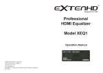
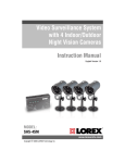
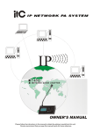
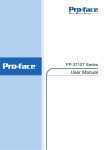
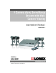
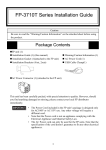
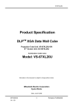
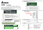
DVI w/digital audio
to HDMI
Converter
The CP-268 combines your digital video(DVI) and audio(SPDIF) input
and converts it to HDMI output. It adds the HDMI output capability
to your DVI sources so new HDMI TVs can be used with your DVI
sources with sound.
Operation Manual
CP-268
This package includes:
- One CP-268 unit.
- One switching power supply.
- User manual.
Features:
* Combines your digital A/V signal and converts it to HDMI output format.
* Adds the HDMI output capability to your DVI sources such as PC or DVD player.
* Input format auto detection: Digital RGB or YPbPr.
* HDCP compliant.
* Plug and play, easy to install.
Operation Controls and Functions
1
2
3
4
1. DVI input: Connects to the DVI output connector of your source equipment.
2. Digital audio (SPDIF) input: Connects to the digital audio output of your
source equipment.
3. HDMI output: Connects to the HDMI input connector of your HDMI display
or swticher.
4. Power input: Plug the supplied 5V DC power supply into the unit and the LED
will illuminate when the power is connected.
Specifications:
* Digital video input: DVI-I connector (but DVI-D input signal only)
* Digital audio input: Coaxial (SPDIF)
* HDMI output: 19-pin HDMI connector
* Compliant with DVI 1.0 & HDMI 1.2
* HDCP is compliant with HDCP 1.1 and downward compatible with HDCP 1.0
* Operation frequency: Up to 165 MHz
* Frequency bandwidth: 1.65Gbps(single link)
* Input/Output resolutions:
PC: VGA@60/72/75/85Hz, SVGA@60/72/75/85Hz, XGA@60/70/75/85/87Hz,
SXGA@60/75/85Hz, UXGA@60Hz, 1152@70/75/85Hz
HDTV: 480p@60Hz, 576@50Hz, 720p@50/60Hz, 1080i@50/60Hz
1080p@24/25/30/50/60Hz
* Dimensions: 105(W) x 76(D) x 30(H)mm
* Power: 5V 1A center-positive
Pin Configuration
A. DVI-D Input Pin Assignment
DVI-Digital(DVI-D): Supports digital-only connections between the host computer
and display. This interface is designed for a 12 or 24-pin connection to enable
single or dual-link mode activation.
1
8 C1 C2
9
C5
17
24 C3
C4
Digital only connector pin assignments
Pin
Signal Assignment
Pin
Signal Assignment
Pin
Signal Assignment
1
2
T.M.D.S Data2-
9
T.M.D.S Data1-
17
T.M.D.S Data0-
T.M.D.S. Data2+
10
T.M.D.S. Data1+
18
T.M.D.S. Data0+
3
T.M.D.S. Data2 Shield
11
T.M.D.S. Data1 Shield
19
T.M.D.S. Data0 Shield
4
N.C.
12
N.C.
20
N.C.
5
N.C.
13
N.C.
21
N.C.
6
DDC Clock
14
+5V Power
22
T.M.D.S. Clock Shield
7
DDC Data
15
Ground (for +5V)
23
T.M.D.S. Clock+
8
No Connect
16
Hot Plug Detect
24
T.M.D.S. Clock-
C1
N.C.
C2
N.C.
C3
N.C.
C4
N.C.
C5
N.C.
B. HDMI Output Pin Assignment
Pin#
1
3
5
7
9
11
13
15
17
19
1
19
2
18
Function Assignment
TMDS Data2+
TMDS Data2TMDS Data1 Shield
TMDS Data0+
TMDS Data0TMDS Clock Shield
CEC
SCL
DDC/CEC Ground
Hot Plug Detect
Pin#
2
4
6
8
10
12
14
16
18
Function Assignment
TMDS Data2 Shield
TMDS Data1+
TMDS Data1TMDS Data0 Shield
TMDS Clock+
TMDS ClockReserved (N.C. on device)
SDA
+5V Power
Connection and Installation
(1) HDMI display
HDMI Plasma,
LCD or DLP TVs
Computer
DVI cable
DVD
HDMI cable
or
SPDIF Cable
(2) HDMI switcher
HDMI Plasma,
LCD or DLP TVs
Computer
DVI cable
or
DVD
HDMI Switcher
HDMI cable
SPDIF Cable
HDMI cable