Download user`s manual - Portable Clamp On Transit Time and Doppler Flow
Transcript
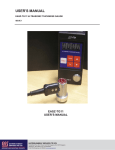
EASZ-TG11 ULTRASONIC THICKNESS GAGE USER'S MANUAL Version V1.0 NA IMPORTANT WARNING Please read this manual entirely before attempting to operate the EASZ-TG11. Improper use can lead to incorrect results and damage to the gage. All statements, technical information and recommendations contained in this manual are based on tests we believe to be reliable, but the accuracy or completeness thereof is not guaranteed. Before using the product you should determine its suitability for your intended use. The end user bears all risk in connection with the use of this product. You are reminded that all warranties as to merchantability and fitness for purpose are excluded from the contract under which the product has been supplied to you. The seller’s only obligation in this respect is to replace such quantity of the product proved to be defective. NEITHER THE SELLER NOR THE MANUFACTURER SHALL BE LIABLE EITHER IN CONTRACT OR TORT FOR DIRECT OR INDIRECT LOSS OR DAMAGE (WHETHER FOR LOSS OR PROFIT OR OTHERWISE), COSTS, EXPENSES OR OTHER CLAIMS FOR CONSEQUENTIAL OR INDIRECT COMPENSATION WHATSOEVER (AND WHETHER CAUSED BY THE NEGLIGENCE OF EESIFLO, ITS EMPLOYEES OR AGENTS OR OTHERWISE). Table of Contents INTRODUCTION ................................................................................... 1 How the TG11 Works ............................................................................ 1 AREAS of APPLICATION ..................................................................... 2 PARTS and CONTROLS ...................................................................... 3 UNITS OF SONIC VELOCITY .............................................................. 4 SWITCHING BETWEEN METRIC AND IMPERIAL ............................. 4 CALIBRATION ...................................................................................... 5 Calibration for Mild Steel ....................................................................... 5 Calibration with Known Sonic Velocities ............................................... 5 Calibration with Unknown Sonic Velocities ........................................... 6 THICKNESS MEASUREMENT TECHNIQUES .................................... 6 Ensure Surfaces are Clean ................................................................... 7 Apply Acoustic Couplant ....................................................................... 7 Cross-Talk Barrier ................................................................................. 7 Rough or Grooved Surfaces ................................................................. 7 Measuring on Cylinders ........................................................................ 8 Measuring on Non-Parallel Surfaces .................................................... 8 The Effects on Materials & Temperature .............................................. 8 Typical Sonic Velocity Table ................................................................. 9 Battery Care and Use .......................................................................... 10 Precautions ......................................................................................... 10 EASZ-TG11 Specifications ................................................................. 11 2 EASZ-TG11 USERS MANUAL INTRODUCTION The EASZ-TG11 is a hand held microcontroller based ultrasonic thickness gage. It operates on two AA batteries and is very easy to use. Please read this manual and follow the instructions carefully to get the best results from your instrument. How the TG11 Works The EASZ-TG11 Thickness Gage is a "TRANSIT TIME MEASURING DEVICE" which works on the “pulse-echo” principle. A burst of ultrasonic energy is generated by a piezo-electric crystal contained on one side of the transducer. This burst of sound travels from the Transmit transducer, past the “Cross Talk Barrier” through a layer of ultrasonic couplant and is transmitted into the material being measured. The pulse then travels through the material being measured until it reaches a material of a substantially different acoustic characteristic (e.g. air or liquid) which then acts as a transmission barrier, reflecting a portion of the energy back to the Receive transducer located on the opposite side of the Cross Talk Barrier. The time required by this burst to make a round trip through the material is accurately measured by the highly stable timing electronics found within the TG11, which then determines the thickness of the material by simply multiplying the Sonic Velocity of that material by the measured Transit Time then dividing the results by 2. Cross Talk Barrier Receive Element Transmit Element Test Material Ultrasonic Pulse 1 AREAS of APPLICATION Any metal, plastic, glass, ceramic or any material which satisfactorily conducts ultrasonic signals, having parallel (or concentric) surfaces can be measured for the thickness. A major application for the TG11 is for assessing wall thinning due to corrosion or erosion. Typical applications include Heat Exchangers Ships Hulls / Decking Tubing and Pipes Airframes / Wings Pressure Vessels Plates / Slabs Castings Billets / Bars Forgings Plastic Sheets / Pipes Boilers Rolls Glass Plates Machined Parts Axles / Wheels / Rails Extrusions Storage Tanks Bridges Steam Lines Flanges 2 EASZ-TG11 USERS MANUAL PARTS and CONTROLS 1- LCD 4 digits indicating readings, battery and probe coupling status indicators and sonic velocity. 2 - PROBE COUPLING INDICATOR Changes to a colon symbol when the probe is NOT acoustically coupled to the material being measured. 3- KEYBOARD Tactile keyboard containing the 5 operation keys. 4- POWER Switches the EASZ-TG11 ON and OFF. 5 - PROBE For probe recognition and zero adjustment. 6- CAL Key Used for calibration of known and unknown materials. 7- Scroll UP and Scroll DOWN keys Used during calibration process to increase or decrease values. 8- CALIBRATION BLOCK Used for probe recognition and zero adjustment. 3 UNITS OF SONIC VELOCITY This is an important concept which must be understood before operating in the “Imperial Mode”. The TG11 has a 4 digit LCD capable of displaying values between 0000 and 9999. In the “Metric Mode”, Sonic Velocities can be displayed in meters per second between 1000 and 9999 m/sec. In the “Imperial Mode”, Sonic Velocities are displayed in Inches per Second divided by 100. For example, the Sonic Velocity of Mild Steel is 5920 meters per second or (5920 / 0.0254=) 233,070 inches per second. To accommodate this 6 digit figure, divide the value by 100, and the resulting value of 2330 should be used for the Sonic Velocity in the Imperial Mode. A table at the back of this manual indicates Sonic Velocities of some typical materials in both Metric and Imperial values. SWITCHING BETWEEN METRIC AND IMPERIAL 1. 2. 3. 4. 5. 6. Switch the TG-11 OFF. Press and hold down the UP scroll key. Switch the TG11 ON by pressing the POWER key. The decimal point will flash from LEFT to RIGHT on the LCD screen. Release the UP scroll key and the decimal point will stop moving. Press the UP scroll key again to move the decimal point to either the LEFT or RIGHT position as follows: Left = Imperial (inch) Right = Metric 7. Press the DOWN scroll key to lock the mode into memory. 4 EASZ-TG11 USERS MANUAL CALIBRATION The calibration process sets up the zero point of the probe and the Sonic Velocity of material being measured as described below. Calibration for Mild Steel This is the simplest calibration method, setting the probe zero point and adjusting the sonic velocity to that of mild steel (5920 m/sec or 233,000 inches/sec) Procedure Apply couplant to the calibration block and press the probe firmly against it. When a stable reading is displayed, press the PROBE key. After one or two seconds the LCD will display 00.20 inches or 005.0 mm indicating the calibration process is complete. The TG11 is now ready for use on mild steel. Calibration with Known Sonic Velocities This method should be employed if you plan on measuring the thickness of anything other than Mild Steel. Procedure Perform Calibration for Mild Steel as defined above. Press "CAL" key twice and the LCD will display 5920 m/sec or 2330 inch/sec, which is the sonic velocity of the mild steel calibration block. Remove the probe from the calibration block and use the “ UP ” or “ DOWN ” scroll keys to adjust the TG11 to the known sonic velocity of the material you are going to measure. For example, if measurements are being made on copper, adjust the Sonic Velocity to either 1835 inches or 4660 meters. Don’t forget that the displayed values of inches per second are actually inches per second divided by 100 A table of the sonic velocities of the most common materials is located in the back of this manual. The TG11 is now ready for use on new material. 5 Calibration with Unknown Sonic Velocities This process should only be used if the Sonic Velocity of the material being measured is unknown, but the thickness of the material is known. Procedure Perform “Calibration for Mild Steel” as detailed above. Apply Acoustic Coupling Compound to the material being measured and couple probe firmly to it. When a stable reading is displayed on LCD Remove the Probe. Press CAL key until the colon symbol disappears. Use the UP or DOWN scroll keys to adjust the displayed reading to the actual thickness of the material being measured. Now Couple the Probe to the material being measured. The LCD should display Actual Thickness of the material being measured. Note: If the probe has been changed, recalibration will be required. Calibration settings are retained within the TG11. If the instrument is not used for long period of time it is advised to re-calibrate the gage. THICKNESS MEASUREMENT TECHNIQUES 6 EASZ-TG11 USERS MANUAL Ensure Surfaces are Clean Prior to attempting to measure the thickness of any material, always remove any dirt, loose scale, corrosion, particles, flaking paint or other foreign substance from the material surface. Apply Acoustic Couplant For smooth surfaces a suitable acoustic couplant is machine oil or even water. For rough surfaces or high temperature applications, a high viscosity couplant such as EESiFlo’s Acoustic Coupling Compound is recommended. Cross-Talk Barrier If you look inside the end of the transducer you will notice a thin metal barrier called the Cross-Talk Barrier running through the center of the transducer, stopping the transmit and receive elements from talking directly to one another. Transmit/Receive Elements Cross-Talk Barrier Rough or Grooved Surfaces For very rough or grooved surfaces a highly viscous acoustic couplant such as that provided with the TG11, is recommended. With a grooved surface, couple the probe to the surface being measured so the probe Cross-Talk Barrier is at right angles to the direction of the grooves. 7 Measuring on Cylinders On cylindrical surfaces probe normality and probe cross-talk orientation is important. To determine normality, rock the coupled probe back and forth along the curved surface direction on the material surface and use the minimum thickness reading, as this represents probe normality. Selection of probe cross talk barrier orientation depends on the material surface diameter. On large surface diameter, orient the probe so that its barrier is perpendicular to the cylindrical axis of the material. On smaller diameter, initially orient the probe barrier both perpendicular to and parallel with material cylindrical axis and then use the direction that gives smaller thickness. Measuring on Non-Parallel Surfaces The surface on either side of a section must be relatively parallel or concentric in order to obtain a satisfactory ultrasound echo for a thickness reading. Non parallel or tapered surface will yield either less accurate or possibly no reading at all The Effects on Materials & Temperature Both dimensions and sound velocity change with temperature, which in turn affects calibration. Normally, the effect can be ignored for the modest changes in ambient temperature but it is always a good practice to re-calibrate when a noticeable change in ambient temperature occurs. The situation becomes even more complex when the material temperature is considerable different than ambient. One solution is to calibrate on a reference sample at same temperature as the material. Another solution is to calibrate on a reference sample at ambient temperature and then add an experimentally derived correction factor for the temperature of the material. 8 EASZ-TG11 USERS MANUAL Typical Sonic Velocity Table Approximate Sonic Velocity values for a variety of common Industrial materials. Materials Acrylic Resin Aluminium Brass, Naval Bronze, Phosphor Cast Iron Copper Glass, Window Inconel Iron Magnesium Monel Nickel PE PVC Quartz Glass Steel Casting Steel, Mild Steel, 4330 Steel, 303 Titanium Zinc Zirconium Sonic Velocity (inch/sec)/100 Sonic Velocity (m/sec) 1051 2488 1744 1390 1811 1835 2673 2252 2323 2484 2370 2217 921 945 2193 2303 2330 2303 2228 2390 1642 1831 2670 6320 4430 3530 4600 4660 6790 5720 5900 6310 6020 5630 2340 2400 5570 5850 5920 5850 5660 6070 4170 4650 9 BATTERY CARE and USE Low Battery indication is provided by the LCD blinking for up to ½ hour. Charge or replace batteries. The TG11 operates on any AA type dry, alkaline, or Ni-Cd batteries. When using Ni-Cd batteries, the batteries should be charged prior to being used. Precautions Avoid shock to instrument or probe. Wipe the couplant off the probe and calibration block after use. Plug and unplug cables with care. Check polarity. Replace any probe which is malfunctioning or showing excessive or uneven wear. Remove the batteries from TG11 if you are not going to use it for a long time. 10 EASZ-TG11 USERS MANUAL EASZ-TG11 SPECIFICATIONS Measurable Materials: Measuring Range: Probe: Key Pad: Steel, Cast Steel, Cast Iron, Aluminum, Other Metals, Hard plastics, Glass, Ceramics 0.04” to 11.8” (1 to 300mm) Dual Crystal Transmit/Receive Type Sealed Tactile Response Velocity: 39,300 to 393,700 inches/sec. (1000 to 9999 m/sec,) Display: 4 digit LCD Resolution: Accuracy: V path Correction: Calibration: Battery: Operating Time: Low Battery: Auto Power Off: Size: Weight: Housing: 0.004” (0.1mm) ± 0.004” (below 2.5”) ± 0.3% (above 2.5”) or ± (0.1mm below 60mm, ± 0.3% above 60mm) Built-In for improved accuracy One Step Calibration Two AA Dry Cells or NiCad Up to 20 hours with Alkaline cells Blinking LCD for ½ hour 3 minute delay 5” (H) X 2.5”(W) X 1.2”(T) (125mm X 65mm X 30mm) 7 ounces with batteries (200 grams with batteries) ABS molded Plastic 11 NOTES 12 EASZ-TG11 USERS MANUAL Please direct all questions to: EESiFlo Inc. 219 East Main Street Mechanicsburg, PA, 17055 Toll-Free Phone: (866) EESIFLO (866-337-4356) or: (717) 697-8546 Fax: (717) 697-2122 Email: [email protected]


