1
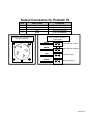
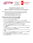
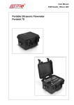
219 East Main Street
Mechanicsburg, PA, USA
17055
Toll Free: 866-EESIFLO
Fax: (717) 697-2122
Simplified Installation of the 4-20mA Output feature
on the EESiFlo Portalok 7S Ultrasonic Flow Meter
Note:
The 4 to 20 mA output on the Portalok 7S is an
“ACTIVE” OUTPUT
Setting up the 4-20 mA output on the Portalok 7S Ultrasonic Flow Meter involves four distinct steps.
1. Define the Pipe and Medium Parameters (PAR on the main menu)
2. Setting up the 4 to 20 mA output (SF on the main menu)
3. Selecting the Output Options (OPT on the main menu)
4. Enter the Measure Mode (MEA on the main menu)
Defining the Pipe and Medium Parameters >PAR<
1) Start by turning the instrument ON by pressing the PWR button
2) Plug the Transducers into the meter.
3) Press the B button one time to ensure you are at the Main Menu.
4) Using the arrow buttons move to the PAR (Parameter) menu, then press the Enter button.
5) Enter the pipes Outer Diameter then press the Enter button.
6) Or, if the pipes diameter is not known, simply enter 0.00 in the diameter and the meter will prompt
you to enter the Pipe Circumference.
7) Enter the pipes Wall Thickness, then press the Enter button.
8) Select a Pipe Material
9) At the Lining Menu use the arrow buttons to select YES or NO, then press Enter. If you answered YES,
then enter the Lining Type and then the Lining Thickness
10) At the Roughness menu enter the estimated internal roughness of the pipe, then press the Enter
button. Default is 0.004 inch.
11) Select the Medium by using the arrow buttons to scroll up and down through the available list. Once
you have found the proper pipe material press the Enter button.
12) Enter the approximate Medium Temperature, then press the Enter button.
13) Enter the amount of Additional Cable, then press the Enter button and you'll return to the Main
Menu. Default is 0 feet.
Page 1 of 4
Setting up the 4 to 20 mA Output >SF<
1. Plug the Outputs cable into the meter.
2. Using the arrow buttons move to the SF (Special Function) menu, then press the Enter button.
3. Using the arrow buttons select System Settings, then press the Enter button.
4. Using the arrow buttons select Proc. Outputs, then press the Enter button.
5. At the Install Output screen use the arrow buttons to select Current I1, then press the Enter button.
6. At the I1 disable screen use the arrow buttons to select NO, then press the Enter button.
7. At the Source Item screen use the arrow buttons to select the type of output you want the 4 to 20 mA
output signal to reflect, then press the Enter button. Default is Measuring value.
8. At the Measuring value screen use the arrow buttons to select the output you want the 4 to 20 mA
output signal to reflect, then press the Enter button. Default is Flow.
9. At the I1 Output Range screen use the arrow buttons to select 4/20 mA, then press the Enter button.
10. At the Error-value screen use the arrow buttons to select which value you’d like output if an error is
encountered, then press the Enter button.
11. Hook a multi-meter set to measure Active mA outputs to the (C + Red) and (D – Black) terminals on the
outputs cable terminal block. Place the multi-meter in the DC current measuring mode.
12. At the I1= Active Loop screen press the Enter button.
13. At the I1:Output Test screen, enter a valid number between 4 and 20 mA, then press the Enter button.
The value you entered will be output by the Portalok 7S and should appear on the multi-meter.
14. At the Again ? screen you can select YES and enter another number to test, or enter NO. It is
recommended that you answer YES a number of times and enter a couple of values between 4 and 20
mA to ensure the 4-20 mA output feature is functioning correctly.
15. Once you’ve answered NO to the above screen you’ll be returned to the System Settings Menu.
16. Press the B button once and you’ll return to the Main Menu, and the 4 to 20 mA output on your multimeter will drop to 0 mA.
Setting the Output Options >OPT<
1. Using the arrow buttons move to the OPT (Output Options) menu, then press the Enter button.
2. At the Physical Quantities screen use the arrow buttons to scroll up and down through the available
list. Once you have found the proper quantity press the Enter button. Default is Volume Flow.
3. At the Volume in: screen use the arrow buttons to scroll up and down through the available list. Once
you have found the proper value press the Enter button. Default is USgpm.
4. Choose a Damping (averaging) time in seconds then press the Enter button. Default is 30s.
5. At the Store Measured Data screen select NO, then press the Enter button or YES if required.
6. At the Serial Output screen select NO, then press the Enter button or YES if required.
Page 2 of 4
7. At the Current Loop I1: screen select YES, then press the Enter button.
8. At the Measured Values screen select either Absolute or Signed to indicate if you would like only
positive (Absolute) or both positive and negative (Signed) flow, then press the Enter button. Default is
Absolute.
9. At the Zero-Scale Value screen enter a value that will represent the 4 mA output signal, then press the
Enter button.
10. At the Full-Scale Value screen enter a value that will represent the 20 mA output signal, then press the
Enter button.
11. At the Alarm Output screen select NO, then press the Enter button or YES if required. Once entered
you will return to the Main Menu.
Enter the Measure Mode >MEA<
1) Using the arrow buttons move to the MEA (Measuring) menu, then press the Enter button.
2) At the Sound Path screen choose a Sound Path that matches your exact needs, then press the Enter
button. Please see page 25 in the Portalok 7S User’s Manual for further information.
3) At the Transducer Distance screen this indicates how far apart the transducers must be separated.
4) Select an appropriate transducer Installation Site by following the guidelines in the manual on pages
17-19.
5) Apply Ultrasonic Couplant to the bottom of the Transducers
6) Install Transducers with arrows pointing in the same direction, with the arrow pointing in the normal
direction of flow.
7) Ensure Transducers are correct distance apart by pressing ENTER and reviewing the SIGNAL STRENGTH
as discussed in the manual on page 27.
8) A GREEN signal indicates you have sufficient signal strength to begin measuring. A RED signal indicates
you should re-check your transducers installation.
9) Press ENTER again to confirm the transducer separation distance, and you will begin displaying the
flow data you've selected, and outputting the appropriate value via the 4 to 20mA output!!!
Once measurements are complete, press the PWR button for 3 seconds to turn the instrument off, and it will
retain your setup information for your next installation.
Page 3 of 4
Output Connectors for Portalok 7S
Pin
Wire Color
Function
A
B
C
D
White
Green
Red
Black
Open Collector Positive
Open Collector Negative
4-20 mA Positive
4-20 mA Negative
Female Output Connector on
side of Portalok 7S
Inline connector on end of
Output Cable
WHITE
A
A
Open Collector Positive
B
Open Collector Negative
C
4-20 mA Positive
D
4-20 mA Negative
GREEN
D
RED
B
C
BLACK
Page 4 of 4