1
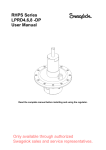
RB
USER MANUAL
Read the complete manual before mounting and using the regulator.
RBH4,6,8 User Manual
Rev.date: 20-09-2010
2
WARNING
INCORRECT OR IMPROPER USE OF THIS PRODUCT CAN CAUSE SERIOUS PERSONAL INJURY
AND PROPERTY DAMAGE.
Due to the variety of operating conditions and applications for this product, the user is solely responsible
for making the final proper decisions concerning the correct assembly and functioning of the product and
assuring that all the performance, safety and warning requirements are met.
•
•
•
•
•
•
•
•
•
•
•
Users must be trained and equipped for the handling, use and servicing of pressure products and
systems.
Users must contact their gas or liquid supplier for specific safety precautions and instructions.
Gaseous media should be free of excessive moisture to prevent icing at high flow.
Always wear the appropriate protective clothing, including safety glasses, gloves etc. if required.
Follow the applicable safety and maintenance procedures.
Obey specific local regulations.
Do not exceed the maximum inlet and outlet pressure of the product or its accessories.
Operate within the temperature limits and other conditions specified for the product.
Do not drop or damage the product in any other way. This may negatively effect the performance
of the product which can cause the product to malfunction.
Venting fluids and gases can be dangerous. Vent to a safe environment away from people.
Ensure adequate ventilation.
This product is not oxygen clean and therefore not suitable for oxygen service.
If there are questions or problems regarding the installation, operation and maintenance these should be
directed to the proper authority on site before continuing.
RBH4,6,8 User Manual
Rev.date: 20-09-2010
3
CONTENTS
1 Introduction ........................................................................................................................................ 4 1.1 2 Detailed description ...................................................................................................................... 4 Installation .......................................................................................................................................... 4 2.1 Points of attention before installation ........................................................................................... 4 3 Operation ............................................................................................................................................ 4 4 Maintenance ....................................................................................................................................... 5 4.1 5 Disassembly ................................................................................................................................. 5 Trouble shooting ............................................................................................................................... 5 RBH4,6,8 User Manual
Rev.date: 20-09-2010
4
1
Introduction
A ratio backpressure regulator is a pneumatically loaded dome regulator.
The pilot pressure to the dome is usually a low pressure, 0-7 bar air signal. (check drawing for exact
pressure details).
The ratio between the pilot pressure and the dome can be as much as 1:50, depending on the model.
1.1
Detailed description
The pilot pressure signal is fed into the dome chamber onto the large area control diaphragm. This
diaphragm is mechanically linked to the sensing element which has a much smaller area.
The sensing element can be either a diaphragm or a piston.
The difference in areas creates a multiplying effect of sorts. Consequently a ratio backpressure regulator
can be installed in a high pressure system while using a low pressure pilot signal.
The regulator comprises a body and dome joined together by bolts. The body has a removable seat, and a
valve poppet. A diaphragm assembly or piston is inserted into the dome.
2
Installation
RHPS Series regulators have bspp parallel connections. Therefore use only connectors/fittings with bspp
parallel threads.
Do not use sealing compounds which harden. Be careful with anaerobic (Loctite type) compounds.
The compounds can run into the regulator and lock moving parts.
2.1
Points of attention before installation
-
Carefully clean all pipes and connections. Any swarf, lint, wire etc. may cause seat leakage.
The system should contain a filter.
Shut-off valves should be installed.
-
Warning:
Even though SWAGELOK B.V. ratio backpressure regulators are soft-seated for leak-tight shut-off
at zero flow, they should not be left pressurised for extended periods.
Definitely down-stream a valve should be installed to avoid unwanted pressure build-up.
Backpressure regulators do not contain a filter. A proper 10-15 micron filter must be installed. Not
applying a filter can jeopardize the warranty.
Gaseous media should be free of excessive moisture to prevent icing at high flow.
3
Operation
-
-
The pilot pressure can only be of a gaseous nature.
In gaseous systems the pilot pressure can be taken from the high pressure inlet or from a separate source.
In liquid systems the pilot pressure can exclusively be taken from a separate gas source.
The pilot pressure has to be controlled by a self-venting type of pressure regulator. Increasing the pilot
pressure will cause the outlet pressure of the regulator to increase by the factor of the ratio.
E.g., if the ratio is 1:20, then 6 bar pilot pressure results in 120 bar outlet pressure.
Increasing the pilot pressure to 7 bar results in 140 bar outlet pressure.
RBH4,6,8 User Manual
Rev.date: 20-09-2010
5
4
Maintenance
All ratio regulators require maintenance at scheduled intervals.
Annual maintenance is recommended under normal use. More frequent maintenance may be required in
heavy duty service.
A high standard of maintenance would be to clean the entire regulator and to replace all soft parts.
4.1
Disassembly
Piston models
Depressurize the system.
Disconnect the pilot connection.
Loosen bolts on the top diaphragm housing.
Remove the top diaphragm housing.
Remove control diaphragm.
Loosen bolts in the bottom diaphragm housing.
Remove the bottom diaphragm housing.
Remove piston/valve assembly.
Loosen body plug.
Loosen valve seat 11.
Reverse the process for assembly.
5
Trouble shooting
Problem:
Constant leakage from the outlet port before the relief set pressure is reached.
Cause:
A damaged valve and/or seat.
Solution:
Replace.
Problem:
Leakage around the body plug.
Cause:
A damaged o-ring or insufficient torque on the body plug.
Solution:
Replace.
Problem:
Leakage between the body and dome.
Cause:
A damaged seal.
Solution:
Replace.
Problem:
Leakage between the upper and lower dome flanges.
Cause:
A damaged diaphragm.
Solution:
Replace.
Problem:
The regulator will not relief at the set point.
Cause:
The valve stem is sticking.
Solution:
Check the set pressure and the pilot regulator.
Warranty Information
Swagelok products are backed by The Swagelok Limited Lifetime Warranty.
For a copy, visit swagelok.com or contact your authorized Swagelok representative.
RBH4,6,8 User Manual
Rev.date: 20-09-2010