1
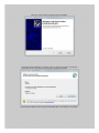
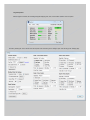
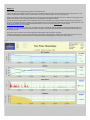
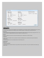
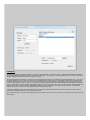
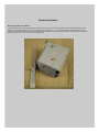
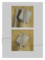
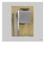
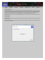
SkyAlert User’s Guide SkyEye SkyAlert SkyRoof Ordering SkyEye Users Forum Support General Program Functions: The SkyAlert Weather program serves as an observatory weather station to monitor prevailing weather conditions. At its core, one of the main functions of the program is to generate a one line weather data file (sometimes known as "Clarity", “Boltwood II” or "Weather Data") which can be used by many imaging software packages (CCD Autopilot, CCD Commander, ACP etc.) to determine if an imaging session should be terminated or paused due to unfavorable weather conditions. Other program functions include realtime charting of weather data and ataglace weather condition reporting. The program also works with the SkyRoof application to facilitate weather dependant rolloff roof operation. This program is designed to work in conjunction with the SkyAlert weather system module and will not function correctly with other weather data generating instruments. Program Installation: Do not connect the SkyAlert weather module to the computer until the software installation is completed. Install the program by doubleclicking the "SkyAlert Setup" icon. Follow the onscreen prompts to proceed with the software installation. When the following screen is displayed, click the “Install Drivers” button to continue with the driver installation. Follow the onscreen prompts to continue with the driver installation. After the device drivers installation has completed, continue by clicking the “Exit” button on the SkyAlert Install program window. Click “Install” on the next window to complete the installation. After finishing the installation, connect the SkyAlert module USB cable to a free USB port on the computer. Program Operation: When the program is started, the main dialog will appear displaying time, date, current weather conditions and a few options. Proceed by selecting the "Tools" selection from the drop down menu and clicking on the "Settings" option. This will bring up the "Settings" page. The settings instructions are sorted by groups starting at the top left of the settings page. Program Settings: In order for the program to function, it will need to collect data from the SkyAlert weather module. Two different methods of data collection are provided for this purpose, “Local” connection or “Remote” connection. Using the “Local” connection means the weather module is connected directly to a USB port on the computer running the program. For “Remote” connections, the weather module is connected to a networked computer running the SkyAlert Remote program and the data is retrieved over a network connection. This method can be useful for connecting multiple computers to a single weather system module or as a failsafe backup in case a module malfunctions. Either way, the computer connected to the weather module will need to have the hardware drivers installed and will need to be running either the SkyAlert program or the SkyAlert Remote program. Local Connection: Connect the weather module to a free USB port on the computer, select the “Local” radio button, select the appropriate com port from the drop down Com Port selection menu and click the “Connect” button. If you are uncertain which port the weather module is connected to, continue selecting com ports until the label adjacent to the Connect button indicates that the device is connected. Note: As long as there are no hardware changes, this only needs to be done the first time the program is run. On subsequent sessions, the program will automatically connect to the module when it is launched. Remote Connection: Before continuing, connect the SkyAlert module to the remote computer and launch the SkyAlert Remote program. Launch SkyAlert on the local computer, open the Settings page and click “Remote” radio button. A navigation button adjacent to it will appear. Click on the button and navigate to the location of the data file generated by the SkyAlert Remote program. (The default name for this file is “remotedata.txt”). Note: As long as there are no file location/name changes, this only needs to be done once. On subsequent sessions, the program will automatically connect to the remote file. Enable Backup Sensor: Check this box if an auxiliary remote weather module is connected to another computer on the network. Data Update Interval: The “Data Update” setting determines how often the data is retrieved from the weather module. The default interval is twenty seconds. Always On Top: Ticking the “Always on Top” checkbox will keep the main menu as the topmost window when displaying other program windows concurrently. Reset Com Port: Click this button to reset the serial port the board is connected to. SkyAlert will automatically attempt to reset the port if a malfunction is detected. Weather Data File Settings: Tick the appropriate temperature scale button to set the system temperature scale to the desired units. When the “Create Weather File” checkbox is ticked, the program will generate and save a standard one line weather data file (i.e. Boltwood II) to a specified file location. Click on the adjacent “Save to” button to select a name and file path to save the file to. The “Cloudy Offset” setting can be adjusted to determine when the sky is cloudy. This number is the difference of the measured sky temperature subtracted from the measured ambient temperature and will determine when the weather data file reports a cloudy condition. You may need to adjust this setting to suit your particular climate or conditions. The default value is 17 degrees Celsius or 31 degrees Fahrenheit. The “Wind Limit” setting determines the maximum allowable wind speed before an unsafe wind speed alert is reported in the weather data file. Graph Settings: Set the name of the graphs page by typing a name in the “Graph Page Title” text field. The “Graph Timeline” setting determines the length of the timeline the graph will show. This can be set from one to three days. Once the timeline setting has been reached, the oldest graph data will be overwritten. Ticking the “Always on Top” checkbox will keep the graph page topmost over other open windows programs. Tick the “Save Graph Image to File” checkbox if you would like a snapshot of the graph saved as an image file. This is necessary if you plan on uploading an image of the graph to the web. Click on the adjacent “Save to” button to set a name and file path to save the image to. Image files can be saved as .png or .jpg. A new image will be generated each time the weather data is updated. When the ftp client is connected, the current graph image will be uploaded to the host. The “Reset All Graphs” button zeroes out the data on all four graphs. Graph 14: Specify the title name of each graph by typing a name in the “Graph title” field. If Graph 1 is set to chart the Ambient Temperature and the Sky Temperature (default), the chart will fill in the area between the two graph lines with a color coded zone indicating the condition of the sky. (Clear, Cloudy or Very Cloudy). Otherwise, Graph 1 is strictly a line type graph. Graphs 24 can display charted values in a line type format or an area type format by ticking the appropriate check box. In addition, area type graphs can be displayed as a solid area or a semitransparent area allowing other plotted data on the graph to be visible. You can specify which weather conditions will be charted on each of the four custom graphs by checking the weather criteria check boxes and include as many plots as desired on each graph. In addition, an external temperature sensor can be monitored and graphed by ticking an “Ext. Sensor” check box. This function is only available when running SkyAlert with SkyAlert Remote connected to an external Phidget 1051_2 sensor. Contact [email protected] for details. The minimum and maximum values of the YAxis of each graph can be set to automatically scale the adjustment by clicking the “Autoscale” radio button Alternatively, you can set the minimum and maximum values of the graph by selecting the Min/Max radio button and entering the desired settings in the Min and Max text fields. Type a name for the YAxis title in the YAxis title field which will be displayed at the left hand side of the graph. Clicking the “Graph” check box on the main menu will show the current graphs. If the graph page is hidden by unticking the graph check box on the main menu, the data is still being recorded and charted in the background and can be displayed again by rechecking the “Graph” check box. Calibrate sensors: Moisture Sensor: The values for the moisture sensor can be adjusted to fine tune the thresholds for dry, damp and rain if needed. The measured value currently generated by the weather module is displayed below the adjustment setting to facilitate the adjustment. The default values are Dry=990 and Rain=970. Wind Sensor: The zero wind speed setting can be adjusted to fine tune the wind speed setting. Adjust the setting so that the wind speed is slightly above zero (i.e. .001) when the wind sensor is completely shielded from any breeze or turbulence. The default value is .010 IR Sensor: Normally, the calibration of the IR sensor can be left at the default setting of zero. Adjustments can be made if necessary. Light Sensor: The light sensor can be calibrated to match your particular environment and installation position. The default values are Day=500 and Dark=250. Ambient Sensor: The Ambient temperature sensor can be calibrated if needed. The default setting is zero. Humidity Sensor: Default is zero. Cloudy/Very Cloudy Offset: This adjustment dictates the difference between a Cloudy condition and a Very Cloudy condition. You may have to experiment with this setting to get optimum results. Ftp Settings: Weather graph images can be optionally uploaded to a web host for web page display. To connect to a web host, enter hosting credentials in the Hostname, Username and Password fields and then click the “Connect/Disconnect” button. If a connection is successfully established, in a few moments the list box to the right will populate with the names of the files currently on the server. When the ftp browser list is populated, the contents of the server will appear with folders at the top followed by files listed in alphabetic order. To open any of the folders, double click on the <Folder> title. With the cursor positioned within the file list, right click for more navigation options. After a location has been determined to upload the file to, type in a name for the file in the “Filename” field. (The default filename is weathergraph). This will be the filename used in your html code to display the image on a web site. It is not necessary to add a filename extension as this will be automatically determined by the file image type. The upload interval can be set by adjusting the Upload Interval control to the desired interval time. Click on the “Save” button to save the settings and click the “Close” button to continue. The login credentials and settings only need to entered once. On subsequent program sessions, the software will automatically connect to the web server and upload data to the previously selected location. In addition to uploading the image file, SkyAlert will upload a copy of the one line weather data file in the same folder. This can be be useful for sharing weather data to multiple locations that cannot otherwise access the file. Note: The ftp browser does not support doublenested folder structures. Files can be saved to the root of the server or a folder within the root but not a folder within a folder. Specific Imaging Automation Software Instructions: ACP: Click on “ACP” from the main toolbar at the top of the of the window and select “Preferences”. Click on the tab labeled “Weather”. In the Weather server object ID field, type in ACP.BoltwoodFile Click on the Setup Weather Server button and navigate to the location of the weather data file created by SkyAlert. You may need to change the extension setting in the file browser from .log to (All Files) in order to locate the weather data file. From the main screen menu, select the toolbar drop down item labeled “Weather” and then click “Connect”. After a few seconds, the “WEA” icon should light up indicating weather status. Note: ACP checks the weather status frequently, be sure to set the update interval in SkyAlert to twenty seconds or less when interfacing with ACP. CCD AutoPilot: On the “Setup” page, select “Cloud Sensor” from the “Weather” drop down item box. Click on the “Settings” option from the main menu on the left and then select the “Control Settings” tab at the top of the window. In the “Weather Sensor” group box, click the file path button and navigate to the file location of the weather data file being generated by SkyAlert (weatherdata.txt). To confirm connection, click “Link to Software” on the Setup page. After connecting to the software, click on the “Run” menu item. The current weather conditions should be displayed in the list box on the upper left area of the window. CCD Commander: Click on the “Setup” menu item on the toolbar at the top of the program window, then select the Control/Device tab. From the Weather Monitor drop down, select “Boltwood/Clarity II Remote”. Click on the “...” Button adjacent to the weather monitor path text box and navigate to the location of the SkyAlert weather data file. Now, click on the “Weather Monitor” tab and set the weather action check boxes as desired. From the main menu, click the “Actions” drop down and ensure that the Weather Monitor Action is set to “Enabled”. Additional Features: SkyAlert features many builtin failsafe and redundancy components. In the event of a hardware malfunction or loss of data, the program will generate a message indicating a failure and set a two minute warning. If the issue is not resolved by user interaction within the two minute period, SkyAlert will set an “Alarm” flag in the weather data file. If you are using SkyRoof to control the roof, SkyRoof will attempt to park the telescope(s) and close the roof. Other imaging automation packages will function similarly depending on settings. Refer to your imaging automation software manual for specific details on this function. For missioncritical installations, two SkyAlert modules can be connected to the software concurrently. If the primary module connected to the USB port of the computer should fail, the software will automatically switch to the remote module. In order for the system to function as designed, the backup module must be connected to a separate computer running the SkyAlert Remote program and SkyAlert needs to have successfully connected to the “remotedata” file at least once. For testing, the Sensor Location radio buttons on the Settings page can be changed while the program is running in order to verify proper operation. Weather Data File: The weather data file generated by SkyAlert conforms to the standard oneline Boltwood II “Clarity” file format as follows: Each weather data entry is separated by one or more spaces. From left to right, values are: ● ● ● ● ● ● ● ● ● ● ● ● ● ● ● ● ● ● ● ● ● File write date File write time Temperature scale (Celsius or Fahrenheit) Wind speed scale (Mph or Knots) Sky Temperature Ambient Temperature Sensor Temperature Wind Speed Humidity Dew Point Dew Heater Percentage (not used) Rain Flag Wet Flag Elapsed time since last file write Elapsed days since last write Cloud/Clear flag (1=Clear,2=Light Clouds,3=Very Cloudy) Wind Limit flag (1=Calm,2=Windy,3=Very Windy) Rain flag (1=Dry,2=Damp,3=Rain) Darkness flag (1=Dark,2=Dim,3=Daylight) Roof Close flag Alert flag (0=No Alert,1=Alert) SkyAlert Installation Mounting the SkyAlert Sensor Module: The Sensor Module comes with a mounting bracket. Mount the bracket to the side of the Sensor Module, as shown below,with the (2) #10 screws provided. After mounting the bracket, it may then be clamped to any vertical mast ( ~1" to 11/2" diameter) using the provided bolt and nut. A 1/4" diameter cross hole will be required in the mast for mounting. Orient the weather module so the the top of the unit is facing North. It is important that the infrared sensor has a clear view of the sky with no obstructions. 11/14/2015