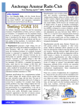
1
l|||||||||||||ll||l||||||||l|||||||||||||||||||||l||||||l||||||||||||l||||||||||||||||||||
US 20050152215A1
(19) United States
(12) Patent Application Publication (10) Pub. N0.: US 2005/0152215 A1
Stuart et al.
(43) Pub. Date:
(54) BLENDER AND SOUND-DAMPENING
Jul. 14, 2005
Related US. Application Data
ENCLOSURE
(60)
(76) Inventors: Jerry E. Stuart, New Hartford, CT
Provisional application No. 60/524,818, ?led on Nov.
25> 2003
(US); Frank R. Chiappetta, Woodbury,
CT (Us); Geracd A. Rutigliano,
Ridge?e1d> CT (Us)
Publication Classi?cation
(51)
Int. Cl? .................................................. .. A47J 43/046
Correspondence Address:
(52)
US. Cl. .......................................... .. 366/205; 366/206
STEVEN A. GARNER
(57)
CONAIR CORPORATION
ONE CUMMINGS POINT ROAD
STAMFORD, CT 06902 (Us)
Ablender has novel sound-dampening enclosure system that
is selectively and conveniently attached to and detached
ABSTRACT
from a blender, or retro-?tted to a blender, utilizing a bottom
(21) Appl, No;
10/997,027
Wall portion for engaging a blender jar base in a ?xed
manner. Another aspect of the blender includes a simpli?ed
control logic using a minimal number of input buttons and
(22) Filed:
Nov. 24, 2004
using user-prompts.
Patent Application Publication Jul. 14, 2005 Sheet 1 0f 9
US 2005/0152215 A1
14
12
22
“24 16
18
/
10
40
126
42
28
\
30
44
32
Bottom View
Sound Enclosure Opened
FIG. 1
Sound Enclosure Closed
FIG. 2
Patent Application Publication Jul. 14, 2005 Sheet 2 0f 9
US 2005/0152215 A1
FIG.7A
ESwBnlociaeutsdnher FIG.6
FIG..
5
Patent Application Publication Jul. 14, 2005 Sheet 3 0f 9
US 2005/0152215 A1
Patent Application Publication Jul. 14, 2005 Sheet 4 0f 9
US 2005/0152215 A1
ow.uE
mm.uE
<w.wE
Patent Application Publication Jul. 14, 2005 Sheet 5 0f 9
US 2005/0152215 A1
9
FIG.
Patent Application Publication Jul. 14, 2005 Sheet 6 0f 9
US 2005/0152215 A1
FIG.10
Patent Application Publication Jul. 14, 2005 Sheet 7 0f 9
US 2005/0152215 A1
FIG.11
Patent Application Publication Jul. 14, 2005 Sheet 9 0f 9
M2PROGR
US 2005/0152215 A1
FIG.13
Jul. 14, 2005
US 2005/0152215 A1
BLENDER AND SOUND-DAMPENING
ENCLOSURE
CROSS-REFERENCE TO RELATED
APPLICATIONS
[0001] None.
easily attached or detached from a blender for use either With
or Without the sound-dampening enclosure, and that pro
vides superior sound dampening, and that has a loW exterior
pro?le. It is also an object of the present invention to provide
a multi-function, programmable blender that has logic con
trols, and input and output means, that prompts a user in a
manner suf?cient to eliminate the need for a user manual and
[0002]
1. Field of the Invention
that requires little control panel space. These are other
objects are achieved by the present invention described
herein.
[0003]
The present invention relates to food and beverage
[0009]
BACKGROUND OF THE INVENTION
The present invention is directed to a blender
blenders and, more particularly to a multiple-feature blender
having a sound enclosure that is adapted to be installed to or
having novel control logic and input and output means, and
removed selectively from, or to retro-?t, existing blenders;
selectively and conveniently attached to and detached from
and to a blender operating system that includes novel
a blender.
operational sequences and programming capabilities.
[0004] 2. Description of Related Art
[0005]
Various food and beverage blenders for home or
commercial use typically include a base that houses an
electric motor and drive assembly including blades that
rotate at very high rates in order to chop, mix or blend food
or beverage ingredients contained in a jar attached to the
base. The noise generated by the blender While it is operating
is often substantial and can be irritating to people in close
proximity to the blender. This problem is signi?cant to a
home user as Well as in a commercial establishment Where
to a blender sound-dampening enclosure system that is
[0010] In a preferred embodiment of the present invention,
the sound-dampening enclosure comprises tWo parts. The
?rst part has three sideWalls, a partial top Wall, and a partial
bottom Wall. The partial bottom Wall is a ?ange-like pro
jection that extends from and along the length of all three
side Walls and that has a relatively narroW Width so that it
forms a square-cornered “C” shape. The partial bottom Wall,
being of a general “C” shape, is adapted to be placed on top
of a blender jar base While enclosing from three sides the
central portion of the jar base Where the blending blade and
spindle project. The ?rst part is held to the jar base by one
or both of screWs or fasteners directly attached to the partial
customers are subject to the sounds of the surrounding
environment.
bottom Wall, and by positioning the partial bottom Wall
[0006] At least one knoWn blender design incorporates a
sound-dampening enclosure. The enclosure incorporates a
jar-pad, Which is commonly a rubber pad that sits on top of
the blender jar base and beneath aj ar that is attached to the
base. The second part of the sound-dampening enclosure is
three-dimensional, generally rectangular box that surrounds
and encloses a blender jar mounted to a base. The enclosure
is opened or closed by lifting a movable section of it that is
hinged to the remaining portion. The sound enclosure is
designed to exclusively ?t the particular base and is, thus,
dedicated to a particular model. Due to its mounting design,
the enclosure cannot be conveniently or quickly attached or
underneath a portion of the blender assembly such as a
shaped similarly to the ?rst part but Without the partial
bottom Wall, and is hingedly connected to the ?rst part and
adapted to be sWung betWeen an opened and closed position.
[0011] Another aspect of the preferred embodiment of the
present invention is directed to a control system having an
detached to or from the base.
electronic display and one or more up/doWn arroW buttons
[0007] Other knoWn aspects of blenders include variable
speed controls, countdoWn timers, pre-set programs, user
de?ned programs, automatic start and stop, and user-input
controls. For instance, knoWn blenders provide pre-pro
grammed selections for running a blender at a speci?c speed
visual indication on the screen. By using an electronic
display and buttons in combination to communicate numer
for scrolling to various selections after being prompted by a
ous prompts and inputs, a relatively large number of opera
tions commands and programming steps can be performed
With a relatively small and uncomplicated control panel.
for a predetermined time. Certain knoWn blenders enable a
user to modify such pre-set programs using push-button
inputs. Among such blenders are a variety of control panels
BRIEF DESCRIPTION OF THE DRAWINGS
that include touchpads, buttons, knobs and LED or LCD
displays. By adding various controls and functions, the
[0012] FIG. 1 is a perspective vieW of a preferred embodi
ment sound-dampening enclosure according to the present
complexity of operation, programming and use sometimes
invention, shoWn in an opened position.
requires that a user refer to a manual during operation. In
addition, numerous buttons and controls on a control panel
take up large amounts of space.
[0013] FIG. 2 is a perspective vieW of the sound-damp
ening enclosure according to the present invention, shoWn in
OBJECTS AND SUMMARY OF THE
INVENTION
[0014] FIG. 3 is a bottom vieW of the sound-dampening
enclosure according to the present invention, shoWn in a
[0008]
It is desirable to provide a blender that overcomes
the shortcomings of knoWn devices and, thus, it is an object
of the present invention to provide a blender having a
sound-dampening enclosure that is adapted to be retro-?tted
to existing blenders of varying siZes that do not have
originally existing sound-dampening enclosures, and that is
a closed position.
closed position.
[0015] FIG. 4 is a top, exploded vieW of the sound
dampening enclosure according to the present invention.
[0016] FIGS. 5, 6 and 7A are—respectively—front, side
and perspective vieWs of the sound-dampening enclosure
Jul. 14, 2005
US 2005/0152215 A1
according to the present invention shown assembled to a
blender base and in a closed position.
[0017]
7A.
FIG. 7B is an exploded vieW according to FIG.
[0018]
FIGS. 8A-8C are—respectively—front, rear and
underneath the jar pad (48). After fastening the screWs (54),
perspective vieWs of a blender jar assembled to a blender
base according to the present invention.
[0019]
FIG. 9 is a schematic vieW of a ?rst embodiment
control panel according to the present invention.
[0020]
A central hole (56) in the pad (48) facilitates a spindle a
rotating blender blade. The blender base (46) and bottom
Wall (22) may be provided With cooperating screW holes (50,
52) that can be lined up and fastened With screWs (54)
FIG. 10 is a schematic vieW of a second embodi
ment control panel according to the present invention.
the jar-pad (48) can be positioned over the bottom Wall (22).
The tWo portions (12, 30) may be constructed of any suitable
material that provides sufficient structural integrity to sup
port itself and hold up to repetitive opening and closing, and
that provides sound insulation. In the preferred embodiment,
the tWo portions (12, 30) of the enclosure (10) are made of
transparent molded plastic.
control panel according to the present invention.
[0026] When the enclosure (10) is mounted to a blender
base (46) as shoWn in FIGS. 5-7A, the enclosure may be
[0022] FIG. 12 is a How diagram illustrating operational
in FIG. 1 and FIG. 2, respectively, to access the space inside
sequences according to a preferred embodiment of the
present invention.
for installing and removing a blender jar (58). When the
enclosure (10) is closed, it dampens noise created by the
[0023]
blender blade moving relative to food or other ingredients
[0021]
FIG. 11 is a schematic vieW of a third embodiment
FIG. 13 is a schematic vieW of a fourth embodi
ment control panel according to the present invention.
DETAILED DESCRIPTION OF THE
INVENTION
[0024] A ?rst embodiment of the present invention is
directed to the sound-dampening enclosure shoWn in FIGS.
1-4. The enclosure (10) comprises a ?rst portion (12) having
a rear Wall (14), tWo side Walls (16, 18), a top Wall (20), and
a bottom Wall (22). The bottom Wall (22) is made of three
sections: a rear section (24), and tWo side sections (26, 28).
selectively opened and closed betWeen the positions shoWn
being blended.
[0027] Another aspect of the preferred embodiment relates
to the function and control input/output system. In a ?rst
embodiment, schematically illustrated in FIG. 9, a control
panel (60) on the front of the blender base (46) has a ?rst
paddle sWitch (62) and a second paddle sWitch (64). The ?rst
paddle sWitch (62) is movable betWeen three positions: “hi”;
“loW”; and “off”, respectively. The ?rst paddle sWitch (62)
is connected through conventional logic circuitry to control
the speed of a conventional blender motor that drives
The rear section (24) eXtends from the rear Wall (14) in a
blender blades positioned through the bottom of the jar (58).
bottom Wall plane. The tWo side sections (26, 28) eXtend
from the side Walls (16, 18), respectively, in the same plane,
sWitch (62) refer to relatively high and loW rotational speeds
so that the bottom Wall (22) generally forms a “C” shaped
section in the bottom vieW of FIG. 3. The enclosure (10)
further comprises a second portion (30) having a front Wall
(32), tWo side Walls (34, 36), and a top Wall (38). The ?rst
and second portions (12, 30) are pivotally connected to each
other by hinge connections (40, 42) on respective sides of
the enclosure (10). The hinge connections (40, 42) may be
of any one of a variety of types that may be molded directly
into the respective side Walls (16, 18, 34, 36) that mate, or
that may be pinned using separate hinge components. A
handle (44) may be molded directly into the front Wall (32)
of the second portion (30), or a separately constructed
handle may be attached.
[0025] In use, the enclosure (10) is mounted to a blender
base (46) as shoWn in FIGS. 5-7A. Referring to FIG. 7B,
the bottom Wall (22) of the ?rst portion (12) is, preferably,
positioned underneath ajar-pad (48) on the blender base
(46). Because the bottom Wall (22) is of a generally “C”
shaped section, it does not interfere With a spindle (47) and
blender blade (not shoWn) that protrude from the center of
the base (46). The jar-pad (48) is preferably a pad made of
rubber that rests upon the blender base (46) top surface (45)
The “hi” and “loW” modes of operation denoted by the ?rst
of the motor driven blender blade. The second sWitch (64) is
movable betWeen tWo positions: “pulse”; and “off”. The
pulse position Will cause the blender blade to rotate While the
second sWitch (64) is held in the pulse position if the ?rst
sWitch (62) is in the off position. The sWitch (64) is a
spring-biased momentary contact sWitch that is biased
toWard the off position so that, if released, the sWitch (64)
Will revert back to the off position. If the second sWitch (64)
is moved to the pulse position While the ?rst sWitch (62) is
in the loW position, the blender blade speed Will increase and
maintain an increased speed as long as the second sWitch
(64) is held in the pulse position. If the second sWitch (64)
is released While the ?rst sWitch (62) is in the loW position,
the speed resumes to the condition prior to activating pulse.
Operation is stopped if the ?rst sWitch (62) is positioned to
the off position.
[0028] In another embodiment, shoWn in FIG. 10, a
control panel (66) has touchpad buttons: “on/off” to turn
poWer on to the blender; “high”“loW” and “stop” to run
blender speeds, respectively, at a relatively high rotational
speed, a relatively loW rotational speed, or no speed; “timer”
(73) “+” and “—” (75) to program a run time upon Which, at
and provides a secure, resilient seat for a blender jar (58),
expiration of a selected time, the blending operation Will
such as that shoWn in FIGS. 8A-8C. Acut-aWay portion (43)
of the pad (48) accommodates the presence of the bottom
Wall (22) of the enclosure (10). For illustrative purposes, the
and held, operates the blender if it is an at rest condition, or
vieWs of FIG. 8A-8C are shoWn Without the enclosure (10)
mounted on the base (46). In use, the enclosure (10) is
mounted to the base (46), as shoWn in FIGS. 5-7A, in a
manner in Which it surrounds and encloses a blender jar (58).
automatically stop; and “pulse” (77) Which, When pressed
speeds up the blender if it is already operating at loW speed.
The control panel (66) also includes a display screen (68)
that displays the run-time remaining if the “timer” feature is
activated. The display screen (68) is preferably an LED, but
may also be an LCD.
Jul. 14, 2005
US 2005/0152215 A1
[0029] Yet another control panel embodiment is shoWn in
FIG. 11, Where a control panel (70) has touchpad buttons
that operate and are arranged essentially the same as the
embodiment of FIG. 10, and hence like reference numerals
are indicated in the illustration, but does not include the
eXample, a set time and speed of operation. If a user Wishes
to replace any one of the programs With a custom program,
the user scrolls on the display screen (81) to a display that
reads: “ADD NEW PROGRAM” (110). The display then
reads: “USE UP/DOWN TO SET TIME: ##” (102), prompt
timer function, and its associated input buttons or display
ing the user to use up/doWn buttons to scroll to a numerical
screen.
entry indicative of time that Will display in the digits “##” .
The user is then prompted to save the program (104) by
pressing a button such as an up/doWn button. Amessage Will
read: “NEW PROGRAM SAVED” (106) and it Will indi
cated Which program number or address is assigned to the
[0030] Another embodiment of the present invention
relates to an interactive screen display With user prompts for
various functions. Referring to the schematic of the control
panel (72) shoWn in FIG. 13 and the ?oW-chart diagram of
FIG. 12, When the blender is initially poWered up using the
“on/off” button (74), a ?rst message (76) greets the user
With, for example, the blender manufacturer name. After a
speci?ed time-out period, the greeting is replaced With a
prompt (78) on the display screen (81) stating “PRESS ANY
BUTTON TO BLEND”. The button choices are from among
neW program so that the user may call it up and activate it
by name.
[0033] While the preferred embodiment has been herein
shoWn and described, it is understood that modi?cation can
be made Without departing from the scope of the claimed
invention.
four pre-programmed sequences (80, 82, 84, 86), maXimum
pulse (88), or normal pulse (90). The user then presses any
button to bring up the neXt display prompt, “FOR LIQUID
DRINKS: ##”, Where “##” is representative of a particular
number that the user enters using either numerical buttons
(80, 82, 84, 86) or, alternatively, a scrolling button (not
shoWn) to select the proper number to make this selection.
If this selection is not desired, the user presses another
button, Which may be pre-programmed from among one of
the present buttons, to advance the display to the neXt
message: “FOR FROZEN DRINKS: ##”. In a similar man
ner, the user may select this selection or move on to
successive prompts that include: “FOR ICE CREAM
DRINKS: ##”; and “FOR SMOOTHIE DRINKS: ##”. For
each of the selections, the numerical code “##” assigned to
a selection is indicative of a particular blender speed setting
suitable for the type of blending operation indicated in the
descriptive prompt. The user makes a selection from one of
the foregoing choices and the blender Will operate at the
What is claimed is:
1. An enclosure for an appliance comprising:
a ?rst section;
a second section;
a hinge for connecting said ?rst section to said second
section Wherein said second section is adapted to
selectively pivot relative to said ?rst section about said
hinge; and
a fastener adapted to selectively secure said ?rst section to
said appliance.
2. An enclosure according to claim 1, further comprising
a base-engaging section on said ?rst section adapted to
engage an appliance base and support said enclosure
thereon.
respective speed. If desired, the blender may be programmed
3. An enclosure according to claim 2, Wherein
to run for a speci?ed duration corresponding to one of the
said base-engaging section comprises a generally ?at
selections in addition to a speci?ed blender speed. Alterna
tively, either one of speed or duration can be set constant for
all of the selections, With the other varying according to the
user input selection.
[0031] When the pulse button (88) is activated, it speeds
up the blender blade rotation rate to 150% that of the normal
portion adapted to rest on said base.
4. An enclosure according to claim 3, Wherein
said generally ?at portion is received betWeen said base
and a ?eXible base cover.
5. An enclosure according to claim 3, Wherein
high setting. Correspondingly, the display screen (81) Will
said generally ?at portion forms a generally “C-shaped”
read “MAX POWER SPEED: 150%”. If desired, instead of
using on of the pre-set selections referred to in the preceding
paragraph, a user may simply activate the start/stop button
6. An enclosure according to claim 2, Wherein
(92) to cause the blender blade to rotate. The display screen
Will read “SPEED: 100%” to indicate that the blender blade
is rotating at full speed. If the user desires to change the
“SPEED+” or “SPEED—” buttons (94, 96) buttons are used
to scroll up or doWn and the display screen (81) Will display
?ange.
said base-engaging section comprises fastener holes
adapted to receive fasteners therethrough for attaching
said enclosure to said base.
7. A blender comprising:
a percentage of the original speed indicative of the speed
a base;
relative to full speed (e.g., “80%”, “50%” etc.).
a blade for processing food;
[0032] Preferably, if the “SMOOTHIE DRINKS” option
ajar above said base adapted to hold said food to be
(98) is selected from one of the pre-set buttons (86, for
processed;
example) the user is prompted (100, 102) to sequentially set
speed and time using, for eXample, the arroW keys (94, 96),
a motor Within said base for driving said blade;
and then prompted to save the settings (104). An indication
of a saved program (106) folloWed by a con?rmation (108)
a control panel comprising:
enables users to create and store neW programs. The blender
a ?rst sWitch having a ?rst position at Which said blade
may be provided With pre-installed programs such as, for
remains stationary, a second position for rotating said
Jul. 14, 2005
US 2005/0152215 A1
blade at a ?rst speed and a third position for rotating
said blade at a second speed that is faster than said ?rst
speed; and
a second sWitch adapted to be depressed to increase the
speed of said blade for the duration of time that said
sWitch is depressed;
and
an enclosure for said blender comprising:
a ?rst section;
a second section;
a hinge for connecting said ?rst section to said second
section Wherein said second section is adapted to
selectively pivot relative to said ?rst section about said
hinge; and
a fastener adapted to selectively secure said ?rst section to
said blender.
a pulse button adapted to increase the speed of said blade
for the duration of time that said button is depressed;
and
an enclosure for said blender comprising:
a ?rst section;
a second section;
a hinge for connecting said ?rst section to said second
section Wherein said second section is adapted to
selectively pivot relative to said ?rst section about said
hinge; and
a fastener adapted to selectively secure said ?rst section to
said blender.
16. A blender according to claim 15, further comprising
a base-engaging section on said ?rst section adapted to
engage an appliance base and support said enclosure
thereon.
17. A blender according to claim 16, Wherein
8. A blender according to claim 7, further comprising
said base-engaging section comprises a generally ?at
a base-engaging section on said ?rst section adapted to
engage an appliance base and support said enclosure
thereon.
portion adapted to rest on said base.
18. A blender according to claim 17, Wherein
said generally ?at portion is received betWeen said base
9. A blender according to claim 8, Wherein
said base-engaging section comprises a generally ?at
portion adapted to rest on said base.
10. A blender according to claim 9, Wherein
said generally ?at portion is received betWeen said base
and a ?exible base cover.
11. A blender according to claim 9, Wherein
said generally ?at portion forms a generally “C-shaped”
?ange.
12. A blender according to claim 8, Wherein
said base-engaging section comprises fastener holes
adapted to receive fasteners therethrough for attaching
said enclosure to said base.
13. A blender according to claim 7, Wherein
said second sWitch is adapted to be depressed to rotate
said blade at said ?rst speed When said ?rst sWitch is in
said ?rst position and at said second speed When said
?rst sWitch is in said second position.
14. A blender according to claim 7, Wherein
said second sWitch further comprises a spring adapted to
bias said second sWitch away from said depressed state.
15. A blender comprising:
a base;
a blade for processing food;
ajar above said base adapted to hold said food to be
processed;
a motor Within said base for driving said blade;
a control panel, said control panel comprising:
a ?rst button for providing or shutting poWer to said
blender;
a plurality of secondary buttons for controlling the rotat
ing speed of said blade; and
and a ?exible base cover.
19. A blender according to claim 17, Wherein
said generally ?at portion forms a generally “C-shaped”
?ange.
20. A blender according to claim 16, Wherein
said base-engaging section comprises fastener holes
adapted to receive fasteners therethrough for attaching
said enclosure to said base.
21. A blender according to claim 15, Wherein
said control panel further comprises a plurality of tirner
buttons adapted to program a duration of time that said
blade rotates.
22. A blender according to claim 21, Wherein
said control panel further comprises a display screen for
displaying the amount of time remaining.
23. A blender according to claim 22, Wherein
said display screen is an LED.
24. A blender according to claim 22, Wherein
said display screen is an LCD.
25. A blender according to claim 15, Wherein
said control panel further comprises a plurality of pro
gram buttons adapted to rotate said blade at a prepro
grarnrned speed.
26. A blender according to claim 25, Wherein
said plurality of program buttons are adapted to rotate said
blade at said preprograrnrned speed for a prepro
grarnrned duration of time.
27. A blender according to claim 15, further comprising
a display screen for displaying information about the
operation of said blender.
28. A blender according to claim 27, Wherein
said display screen is an LED.
29. A blender according to claim 27, Wherein
said display screen is an LCD.
*
*
*
*
*