1
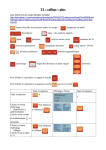
Mounting and
Initial Startup
Chapter
2
In This Chapter...
Safety Information�������������������������������������������������������������������������������������������������� 2–2
Danger!�������������������������������������������������������������������������������������������������������������������� 2–2
Wiring Notes: PLEASE READ PRIOR TO INSTALLATION. �������������������������������������������� 2–2
Applicable Codes���������������������������������������������������������������������������������������������������������� 2–2
Motor Dimensions �������������������������������������������������������������������������������������������������� 2–3
MTF T-Frame Single-phase Farm-Duty Motor Dimensions���������������������������������������� 2–3
MTR(2) 56(H)C-Frame Single-phase Rolled-steel Motor Dimensions ���������������������� 2–3
MTR 56C-Frame Three-phase Rolled-steel Motor Dimensions���������������������������������� 2–5
MTSS 56C-Frame Three-phase Round-body Motor Dimensions������������������������������� 2–6
MTSS 56C-Frame Three-phase Rigid-base Motor Dimensions �������������������������������� 2–6
MTCP Premium-Efficiency T-Frame Three-Phase Motor Dimensions����������������������� 2–7
MTCP Premium-Efficiency TC-Frame Three-Phase Motor Dimensions ������������������ 2–11
MTC EPAct T-Frame Three-Phase Motor Dimensions����������������������������������������������� 2–13
MTC EPAct TC-Frame Three-Phase Motor & C-Flange Dimensions ������������������������ 2–17
Terminal and Wiring Diagrams����������������������������������������������������������������������������� 2–18
IronHorse® Single-Phase Motors ����������������������������������������������������������������������������� 2–18
IronHorse® Three-Phase Motors ������������������������������������������������������������������������������ 2–18
Single-Phase Motors Reversing Diagrams ��������������������������������������������������������������� 2–19
Motor Mounting����������������������������������������������������������������������������������������������������� 2–21
Motor Mounting Orientation�������������������������������������������������������������������������������������� 2–22
Proper Installation Conditions����������������������������������������������������������������������������������� 2–23
Coupling Alignment����������������������������������������������������������������������������������������������������� 2–23
Motor Nameplate & Starter Information�������������������������������������������������������������� 2–24
Typical IronHorse® Motor Nameplate����������������������������������������������������������������������� 2–24
Motor Starter Information ����������������������������������������������������������������������������������������� 2–24
Locked Rotor Amps����������������������������������������������������������������������������������������������������� 2–24
Inspection Before Startup������������������������������������������������������������������������������������ 2–25
Initial Startup Inspection�������������������������������������������������������������������������������������� 2–25
IronHorse® General Purpose AC Motors User Manual – 6th Ed, Rev A – 07/17/2015
Page 2–1
Chapter 2: Mounting and Initial Startup
Safety Information
Danger!
Hazardous Voltage! Before making any connection to the
motor, disconnect all power to the motor.
Warning: Any electrical or mechanical modification to this equipment
without prior written consent of AutomationDirect.com, Inc. will void all
warranties, may result in a safety hazard, and may void the cCSAus listing.
Warning: To avoid physical injury, keep your hands
and clothing away from all moving parts.
Wiring Notes: PLEASE READ PRIOR TO INSTALLATION.
1) During installation, follow all local electrical, construction, and safety codes for the country
in which the motor is to be installed.
2) Make sure the appropriate protective devices (circuit breaker or fuses) are connected
between the power source and motor controller.
3) Make sure that the leads are connected correctly and the motor is properly grounded.
(Ground resistance should not exceed 0.1Ω.)
4) Use ground leads that comply with AWG/MCM standards and keep them as short as
possible.
5) Make sure that the power source is capable of supplying the correct voltage and required
current to the motor.
6) Do not attach or remove wiring when power is applied to the motor.
Applicable Codes
All IronHorse® motors are cCSAus listed, and therefore comply with the requirements of the
National Electrical Code (NEC) and the Canadian Electrical Code (CEC).
Installation intended to meet the cCSAus requirements must follow the instructions provided
in the “Wiring Notes” as a minimum standard. Follow all local codes that exceed cCSAus
requirements. Refer to the technical data on the motor nameplate for electrical and performance
data.
Page 2–2
IronHorse® General Purpose AC Motors User Manual – 6th Ed, Rev A – 07/17/2015
Chapter 2: Mounting and Initial Startup
Motor Dimensions
(Dimensions = inches)
MTF T-Frame Single-phase Farm-Duty Motor Dimensions
PART NUMBER
MTF-002-1C18-182
MTF-003-1C18
MTF-005-1C18
DIM. C
16.65
17.24
18.82
MTR(2) 56(H)C-Frame Single-phase Rolled-steel Motor Dimensions
MTR2 56C-Frame Single-phase Motor Dimensions, 1/3 – 1 hp
PART NUMBER
MTR2-P33-1AB36
MTR2-P50-1AB36
MTR2-P75-1AB36
MTR2-001-1AB36
DIM. C
11.90
11.90
11.90
12.40
IronHorse® General Purpose AC Motors User Manual – 6th Ed, Rev A – 07/17/2015
Page 2–3
Chapter 2: Mounting and Initial Startup
Motor Dimensions (continued) – (Dimensions = inches)
MTR(2) 56(H)C-Frame Single-phase Rolled-steel Motor Dimensions (continued)
MTR2 56(H)C-Frame Single-phase Motor Dimensions, 1-1/2 – 2 hp
PART NUMBER
MTR2-1P5-1AB18
MTR2-002-1AB18
MTR2-1P5-1AB36
MTR2-002-1AB36
DIM. C
12.90
13.90
12.40
12.90
MTR 56C-Frame Single-phase Rolled-steel Motor Dimensions
2.85
5.35
3.23
6.9
1.5 hp
motors
only
0.16
0.188
3/8-16
1.41
5.875
4.5
0.517
0.625
3.7
1.65
L
0.19
0.34 (SLOT)
3
2.75
1.88
3.5
1/2"NPT
0.12
5
6.5
1.73
2.44
2.44
6.5
C
C = 12.4 in; all except 1 & 1.5 hp motors
C = 13 in; 1 hp (1800 rpm) & 1.5 hp (3600 rpm)
C = 13.8 in; 1.5 hp (1800 rpm)
Page 2–4
MTR-xxx-1ABxx IronHorse Motors
(single-phase rolled steel)
L = 8.19”; all except 1.5 hp motors
L = 8.5”; 1.5 hp motors
IronHorse® General Purpose AC Motors User Manual – 6th Ed, Rev A – 07/17/2015
Chapter 2: Mounting and Initial Startup
Motor Dimensions (continued) – (Dimensions = inches)
MTR 56C-Frame Three-phase Rolled-steel Motor Dimensions
5.35
2.85
3.23
6.9
0.16
3/8-16
0.188
1.41
5.875
4.5
0.517
0.625
3.7
1.65
7
0.19
0.34 (SLOT)
3
2.75
1.88
3.5
1/2 NPT
0.12
5
1.73
2.44
2.44
6.5
6.5
C
C = 12.2”;
C = 12.6”;
C = 12.2”;
C = 13.8”;
C = 12.4”;
0.33 to 1hp motors
1.5hp MTR-1P5-3BD18
1.5hp MTR-1P5-3BD36
2hp MTR-002-3BD18
2hp MTR-002-3BD36
MTR-xxx-3BDxx IronHorse Motors
(3-phase rolled steel)
IronHorse® General Purpose AC Motors User Manual – 6th Ed, Rev A – 07/17/2015
Page 2–5
Chapter 2: Mounting and Initial Startup
Motor Dimensions (continued) – (Dimensions = inches)
MTSS 56C-Frame Three-phase Round-body Motor Dimensions
C
AG
5.39
R1/8 BSPT THREADED DRAIN HOLE
4X FRONT, 4X REAR, 90° APART
4X 3/8-16
0.19
Ø4.50
0.52
1.88
Ø6.46
Ø0.62
Ø5.87
B.C.
AC MOTOR WITHOUT FEET
PART NUMBER
DIM. C
MTSS-P33-3BD18R
11.59
MTSS-P50-3BD18R
11.59
MTSS-P75-3BD18R
12.76
MTSS-001-3BD18R
12.76
MTSS-1P5-3BD18R
12.76
MTSS-002-3BD18R
12.76
DIM. AG
9.50
9.50
10.67
10.67
10.67
10.48
MTSS 56C-Frame Three-phase Rigid-base Motor Dimensions
C
AG
5.39
R1/8 BSPT THREADED DRAIN HOLE
4X FRONT, 4X REAR, 90° APART
4X 3/8-16
0.19
Ø4.50
0.52
1.88
Ø0.34 SLOT
3.00
4.00
F3
Page 2–6
Ø0.62
Ø5.87
B.C.
0.50
0.50
0.50
Ø6.46
2.75
AC MOTOR WITH FEET
PART NUMBER DIM. C DIM. AG DIM. F3
MTSS-P33-3BD18 11.77
9.69
n/a
MTSS-P50-3BDxx 11.77
9.69
n/a
MTSS-P75-3BDxx 12.76 10.67
5.00
MTSS-001-3BDxx 12.76 10.67
5.00
MTSS-1P5-3BDxx 12.76 10.67
5.00
MTSS-002-3BDxx 13.50
11.42
5.00
3.50
2.44
2.44
5.50
IronHorse® General Purpose AC Motors User Manual – 6th Ed, Rev A – 07/17/2015
Chapter 2: Mounting and Initial Startup
Motor Dimensions (continued) – (Dimensions = inches)
MTCP Premium-Efficiency T-Frame Three-Phase Motor Dimensions
AB
C
P
***
***
L***
ES
R
S
L***
G
U
D
F1*
F1*
F2*
BA
E
AA**
N-W
E
J
H (hole)
B
A
** F1 mounting shown.
** Some frame sizes are F1/F2 convertible.
*** Frames 143T & 145T have no lifting eyelet.
* Various frame sizes have 2 or 4
mounting holes per mounting foot
(one mounting foot per side).
Dimensions [inches, except as noted]
Premium-Efficiency Three-Phase T-Frame Motors – 1800 rpm
Part Number
HP
NEMA
Frame
A
AA**
AB
B
BA
C
D
E
ES
1
143T
7
3/4”npt 6.89
5.1 2.25 12.47 3.5 2.75 1.41
MTCP-001-3BD18
7
3/4”npt 6.89
6.1 2.25 13.47 3.5 2.75 1.41
MTCP-1P5-3BD18 1-1/2
145T
2
7
3/4”npt 6.89
6.1 2.25 13.47 3.5 2.75 1.41
MTCP-002-3BD18
3
182T
8.9
1” NPT
7.45
6.3 2.75 15.11 4.5 3.75 1.78
MTCP-003-3BD18
5
184T
8.9
1” NPT
7.45
7.1 2.75 16.12 4.5 3.75 1.78
MTCP-005-3BD18
213T
10.5
1” NPT
8.63
7.5
3.5 18.89 5.25 4.25 2.41
MTCP-7P5-3BD18 7-1/2
10
215T
10.5
1” NPT
8.63
9
3.5 20.49 5.25 4.25 2.41
MTCP-010-3BD18
15
254T
12.3 1.5” NPT 12.0 10.3 4.25 23.29 6.25
5
2.91
MTCP-015-3BD18
20
256T
12.3 1.5” NPT 12.0 12.4 4.25 25.06 6.25
5
2.91
MTCP-020-3BD18
25
284T
13.7 1.5” NPT 13.7 12.2 4.75 26.63
7
5.5 3.28
MTCP-025-3BD18
30
286T
13.7 1.5” NPT 13.7 13.7 4.75 28.18
7
5.5 3.28
MTCP-030-3BD18
40
324T
15.3
2”NPT
15.3 12.6 5.25 29.95
8
6.25 3.91
MTCP-040-3BD18
50
326T
15.3
2”NPT
15.3 14.0 5.25 31.24
8
6.25 3.91
MTCP-050-3BD18
60
364T
17.0
3”NPT
17.31 14.6 5.88 32.58
9
7
4.28
MTCP-060-3BD18
75
365T
17.0
3”NPT
17.31 15.6 5.88 34.11
9
7
4.28
MTCP-075-3BD18
100
405T
20
3”NPT
18.07 17.8 6.62 38.35 10
8
5.65
MTCP-100-3BD18
125
444T
22
2x3”NPT 19.07 18.5 7.5 42.52 11
9
6.91
MTCP-125-3BD18
150
445T
22
2x3”NPT 19.07 20.5 7.5
44.5
11
9
6.91
MTCP-150-3BD18
200 445/7T
22
2x3”NPT 19.07 24
7.5 48.03 11
9
6.91
MTCP-200-3BD18
* Various frame sizes have 2 or 4 mounting holes per mounting foot.
** AA dimension is conduit fitting size. F1 mounting shown; some frame sizes are F1/F2 convertible;
refer to T-frame “Motor Specifications” table.
(F2 mounting = conduit entrance on right side facing shaft.)
*** Frame sizes 143T(C) and 145T(C) have no lifting eyelet.
**** TABLE CONTINUED NEXT PAGE (for dimensions F1–U) ****
IronHorse® General Purpose AC Motors User Manual – 6th Ed, Rev A – 07/17/2015
Page 2–7
Chapter 2: Mounting and Initial Startup
Motor Dimensions (continued) – (Dimensions = inches)
MTCP Premium-Efficiency T-Frame Three-Phase Motor Dimensions (continued)
AB
C
P
***
***
L***
ES
R
S
L***
G
U
D
F1*
F1*
F2*
BA
E
AA**
N-W
E
J
H (hole)
B
A
** F1 mounting shown.
** Some frame sizes are F1/F2 convertible.
*** Frames 143T & 145T have no lifting eyelet.
* Various frame sizes have 2 or 4
mounting holes per mounting foot
(one mounting foot per side).
**** TABLE CONTINUED FROM PREVIOUS PAGE (for dimensions A–ES) ****
Dimensions [inches, except as noted]
Premium-Efficiency Three-Phase T-Frame Motors – 1800 rpm
Part Number
HP
F1*
F2*
G
H
J
N-W
L
P
R
S
U
MTCP-001-3BD18
1
n/a
4
0.47
0.34
1.45
2.25
6.90
7.2
0.771
0.188
0.875
MTCP-1P5-3BD18
1-1/2
4
5
0.47
0.34
1.45
2.25
6.90
7.2
0.771
0.188
0.875
MTCP-002-3BD18
2
4
5
0.47
0.34
1.45
2.25
6.90
7.2
0.771
0.188
0.875
MTCP-003-3BD18
3
n/a
4.5
0.52
0.41
1.97
2.75
10.39
9.0
0.986
0.25
1.125
MTCP-005-3BD18
5
4.5
5.5
0.52
0.41
1.97
2.75
10.39
9.0
0.986
0.25
1.125
MTCP-7P5-3BD18
7-1/2
n/a
5.5
0.78
0.41
2.36
3.38
12.26
10.8
1.201
0.312
1.375
MTCP-010-3BD18
10
5.5
7
0.78
0.41
2.36
3.38
12.26
10.8
1.201
0.312
1.375
MTCP-015-3BD18
15
n/a
8.25
0.87
0.53
2.40
4
15.10
14.4
1.416
0.375
1.625
MTCP-020-3BD18
20
8.25
10
0.87
0.53
2.40
4
15.10
14.4
1.416
0.375
1.625
MTCP-025-3BD18
25
n/a
9.5
0.98
0.53
2.68
4.62
16.50
16.0
1.591
0.5
1.875
MTCP-030-3BD18
30
9.5
11
0.98
0.53
2.68
4.62
16.50
16.0
1.591
0.5
1.875
MTCP-040-3BD18
40
n/a
10.5
0.98
0.66
2.76
5.25
18.25
17.5
1.845
0.5
2.125
MTCP-050-3BD18
50
10.5
12
0.98
0.66
2.76
5.25
18.25
17.5
1.845
0.5
2.125
MTCP-060-3BD18
60
n/a
11.25
1.10
0.66
3.15
5.88
21.0
19.1
2.021
0.625
2.375
MTCP-075-3BD18
75
11.25
12.25
1.10
0.66
3.15
5.88
21.0
19.1
2.021
0.625
2.375
MTCP-100-3BD18
100
12.25
13.75
1.18
0.81
3.15
7.25
23.46
21.4
2.45
0.75
2.875
MTCP-125-3BD18
125
n/a
14.5
1.38
0.81
3.35
8.5
26.43
23.4
2.88
0.875
3.375
MTCP-150-3BD18
150
14.5
16.5
1.38
0.81
3.35
8.5
26.43
23.4
2.88
0.875
3.375
MTCP-200-3BD18
200
16.5
20
1.38
0.81
3.35
8.5
26.43
23.4
2.88
0.875
3.375
* Various frame sizes have 2 or 4 mounting holes per mounting foot.
** AA dimension is conduit fitting size. F1 mounting shown; some frame sizes are F1/F2 convertible; refer to
T-frame “Motor Specifications” table.
(F2 mounting = conduit entrance on right side facing shaft.)
*** Frame sizes 143T(C) and 145T(C) have no lifting eyelet.
Page 2–8
IronHorse® General Purpose AC Motors User Manual – 6th Ed, Rev A – 07/17/2015
Chapter 2: Mounting and Initial Startup
Motor Dimensions (continued) – (Dimensions = inches)
MTCP Premium-Efficiency T-Frame Three-Phase Motor Dimensions (continued)
AB
C
P
***
***
L***
ES
R
S
L***
G
U
D
F1*
F1*
F2*
BA
E
AA**
N-W
J
H (hole)
B
E
A
** F1 mounting shown.
** Some frame sizes are F1/F2 convertible.
*** Frames 143T & 145T have no lifting eyelet.
* Various frame sizes have 2 or 4
mounting holes per mounting foot
(one mounting foot per side).
Dimensions [inches, except as noted]
Premium-Efficiency Three-Phase T-Frame Motors – 1200 & 3600 rpm
HP
NEMA
Frame
A
MTCP-001-3BD12
1
145T
7
3/4” NPT
MTCP-1P5-3BD12
1-1/2
182T
8.9
MTCP-002-3BD12
2
184T
8.9
MTCP-003-3BD12
3
213T
MTCP-005-3BD12
5
215T
MTCP-7P5-3BD12
7-1/2
254T
12.3
1.5” NPT
12.0
10.3
4.25
23.29
6.25
5
2.91
MTCP-010-3BD12
10
256T
12.3
1.5” NPT
12.0
12.4
4.25
25.06
6.25
5
2.91
MTCP-015-3BD12
15
284T
13.7
1.5” NPT
13.7
12.2
4.75
26.63
7
5.5
3.28
MTCP-020-3BD12
20
286T
13.7
1.5” NPT
13.7
13.7
4.75
28.18
7
5.5
3.28
MTCP-1P5-3BD36
1-1/2
143T
7
3/4” NPT
6.89
5.1
2.25
12.47
3.5
2.75
1.41
MTCP-002-3BD36
2
145T
7
3/4” NPT
6.89
6.1
2.25
13.47
3.5
2.75
1.41
MTCP-003-3BD36
3
182T
8.9
1” NPT
7.45
6.3
2.75
15.11
4.5
3.75
1.78
Part Number
AA**
AB
B
BA
C
D
E
ES
6.89
6.1
2.25
13.47
3.5
2.75
1.41
1” NPT
7.45
6.3
2.75
15.11
4.5
3.75
1.78
1” NPT
7.45
7.1
2.75
16.12
4.5
3.75
1.78
10.5
1” NPT
8.63
7.5
3.5
18.89
5.25
4.25
2.41
10.5
1” NPT
8.63
9
3.5
20.49
5.25
4.25
2.41
1200 rpm Motors
3600 rpm Motors
MTCP-005-3BD36
5
184T
8.9
1” NPT
7.45
7.1
2.75
16.12
4.5
3.75
1.78
MTCP-7P5-3BD36
7-1/2
213T
10.5
1” NPT
8.63
7.5
3.5
18.89
5.25
4.25
2.41
MTCP-010-3BD36
10
215T
10.5
1” NPT
8.63
9
3.5
20.49
5.25
4.25
2.41
MTCP-015-3BD36
15
254T
12.3
1.5” NPT
12.0
10.3
4.25
23.29
6.25
5
2.91
MTCP-020-3BD36
20
256T
12.3
1.5” NPT
12.0
12.4
4.25
25.06
6.25
5
2.91
* Various frame sizes have 2 or 4 mounting holes per mounting foot.
** AA dimension is conduit fitting size. F1 mounting shown; some frame sizes are F1/F2 convertible;
refer to T-frame “Motor Specifications” table.
(F2 mounting = conduit entrance on right side facing shaft.)
*** Frame sizes 143T(C) and 145T(C) have no lifting eyelet.
**** TABLE CONTINUED NEXT PAGE (for dimensions F1–U) ****
IronHorse® General Purpose AC Motors User Manual – 6th Ed, Rev A – 07/17/2015
Page 2–9
Chapter 2: Mounting and Initial Startup
Motor Dimensions (continued) – (Dimensions = inches)
MTCP Premium-Efficiency T-Frame Three-Phase Motor Dimensions (continued)
AB
C
P
***
***
L***
ES
R
S
L***
G
U
D
F1*
F1*
F2*
BA
E
AA**
N-W
J
H (hole)
B
E
A
** F1 mounting shown.
** Some frame sizes are F1/F2 convertible.
*** Frames 143T & 145T have no lifting eyelet.
* Various frame sizes have 2 or 4
mounting holes per mounting foot
(one mounting foot per side).
**** TABLE CONTINUED FROM PREVIOUS PAGE (for dimensions A–ES) ****
Dimensions [inches, except as noted]
Premium-Efficiency Three-Phase T-Frame Motors – 1200 & 3600 rpm
Part Number
HP
F1*
F2*
G
H
J
N-W
L
P
R
S
U
2.25
2.75
2.75
3.38
3.38
4
4
4.62
4.62
6.90
10.39
10.39
12.26
12.26
15.10
15.10
16.50
16.50
7.2
9.0
9.0
10.8
10.8
14.4
14.4
16.0
16.0
0.771
0.986
0.986
1.201
1.201
1.416
1.416
1.591
1.591
0.188
0.25
0.25
0.312
0.312
0.375
0.375
0.5
0.5
0.875
1.125
1.125
1.375
1.375
1.625
1.625
1.875
1.875
1200 rpm Motors
MTCP-001-3BD12
MTCP-1P5-3BD12
MTCP-002-3BD12
MTCP-003-3BD12
MTCP-005-3BD12
MTCP-7P5-3BD12
MTCP-010-3BD12
MTCP-015-3BD12
MTCP-020-3BD12
1
1-1/2
2
3
5
7-1/2
10
15
20
4
n/a
4.5
n/a
5.5
n/a
8.25
n/a
9.5
5
4.5
5.5
5.5
7
8.25
10
9.5
11
0.47
0.52
0.52
0.78
0.78
0.87
0.87
0.98
0.98
0.34
0.41
0.41
0.41
0.41
0.53
0.53
0.53
0.53
1.45
1.97
1.97
2.36
2.36
2.40
2.40
2.68
2.68
3600 rpm Motors
4
0.47 0.34 1.45 2.25 6.90
7.2 0.771 0.188 0.875
MTCP-1P5-3BD36 1-1/2 n/a
2
4
5
0.47 0.34 1.45 2.25 6.90
7.2 0.771 0.188 0.875
MTCP-002-3BD36
3
n/a
4.5 0.52 0.41 1.97 2.75 10.39 9.0 0.986 0.25 1.125
MTCP-003-3BD36
5
4.5
5.5 0.52 0.41 1.97 2.75 10.39 9.0 0.986 0.25 1.125
MTCP-005-3BD36
5.5 0.78 0.41 2.36 3.38 12.26 10.8 1.201 0.312 1.375
MTCP-7P5-3BD36 7-1/2 n/a
10
5.5
7
0.78 0.41 2.36 3.38 12.26 10.8 1.201 0.312 1.375
MTCP-010-3BD36
15
n/a 8.25 0.87 0.53 2.40
4
15.10 14.4 1.416 0.375 1.625
MTCP-015-3BD36
20
8.25
10
0.87 0.53 2.40
4
15.10 14.4 1.416 0.375 1.625
MTCP-020-3BD36
* Various frame sizes have 2 or 4 mounting holes per mounting foot.
** AA dimension is conduit fitting size. F1 mounting shown; some frame sizes are F1/F2 convertible; refer to
T-frame “Motor Specifications” table.
(F2 mounting = conduit entrance on right side facing shaft.)
*** Frame sizes 143T(C) and 145T(C) have no lifting eyelet.
Page 2–10
IronHorse® General Purpose AC Motors User Manual – 6th Ed, Rev A – 07/17/2015
Chapter 2: Mounting and Initial Startup
Motor Dimensions (continued) – (Dimensions = inches)
MTCP Premium-Efficiency TC-Frame Three-Phase Motor Dimensions
AB
BF
P
C
AJ
AH
***
***
BB
ES
L***
L***
S
AK
BD
R
U
G
BC
F1*
AA**
F1*
F2*
BA
B
E
E
J
H (hole)
N-W
D
A
** F1 mounting shown. Some frame sizes are F1/F2 convertible.
* Various frame sizes have 2 or 4 mounting holes
per mounting foot (one mounting foot per side).
*** Frames 143TC and 145TC have no lifting eyelet.
Part #
MTCPxxx3BD18C
HP
-001-
1
-1P5-
1-1/2
-002-
2
-003-
3
NEMA
Frame
Dimensions [inches, except as noted]
Premium-Efficiency Three-Phase TC-Frame Motors – 1800 rpm
A
AA**
AB
AH
AJ
AK
B
BA
BB
BC
BD
BF
C
143TC
7
3/4”NPT
6.89
1.96
5.875
4.5
5.1
2.25
0.16
0.29
6.5
3/8-16
12.5
145TC
7
3/4”NPT
6.89
1.96
5.875
4.5
6
2.25
0.16
0.29
6.5
3/8-16
13.5
182TC
8.9
1” NPT
7.45
2.37
7.25
8.5
6.3
2.75
0.25
0.38
9
1/2-13
15.1
-005-
5
184TC
8.9
1” NPT
7.45
2.37
7.25
8.5
7.1
2.75
0.25
0.38
9
1/2-13
16.1
-7P5-
7-1/2
213TC
10.5
1” NPT
8.63
2.87
7.25
8.5
7.5
3.5
0.25
0.51
9
1/2-13
18.9
-010-
10
215TC
10.5
1” NPT
8.63
2.87
7.25
8.5
9
3.5
0.25
0.51
9
1/2-13
20.5
-015-
15
254TC
12.3
1.5”NPT
12.0
3.75
7.25
8.5
10.3
4.25
0.25
0.25
10
1/2-13
23.3
-020-
20
256TC
12.3
1.5”NPT
12.0
3.75
7.25
8.5
12.4
4.25
0.25
0.25
10
1/2-13
25.1
-025-
25
284TC
13.7
1.5”NPT
13.7
4.38
9
10.5
12.2
4.75
0.25
0.25
11.25
1/2-13
26.6
-030-
30
286TC
13.7
1.5”NPT
13.7
4.38
9
10.5
13.7
4.75
0.25
0.24
11.25
1/2-13
28.2
-040-
40
324TC
15.3
2” NPT
15.3
5
11
12.5
12.6
5.25
0.25
0.24
14
5/8-11
30.0
-050-
50
326TC
15.3
2” NPT
15.3
5
11
12.5
14.0
5.25
0.25
0.25
14
5/8-11
31.2
-060-
60
364TC
17.0
3” NPT
17.3
5.62
11
12.5
14.6
5.88
0.25
0.25
14
5/8-11
32.6
-075-
75
365TC
17.0
3” NPT
17.3
5.62
11
12.5
15.6
5.88
0.25
0.25
14
5/8-11
34.1
-100-
100
405TC
20
3” NPT
18.1
7
11
12.5
17.8
6.62
0.25
0.25
15.5
5/8-11
38.4
* Various frame sizes have 2 or 4 mounting holes per mounting foot.
** A
A dimension is conduit fitting size. F1 mounting shown; some frame sizes are F1/F2 convertible; refer to T-frame
“Motor Specifications” table.
(F2 mounting = conduit entrance on right side facing shaft.)
*** Frame sizes 143T(C) and 145T(C) have no lifting eyelet.
**** TABLE CONTINUED NEXT PAGE (for dimensions D–U) ****
IronHorse® General Purpose AC Motors User Manual – 6th Ed, Rev A – 07/17/2015
Page 2–11
Chapter 2: Mounting and Initial Startup
Motor Dimensions (continued) – (Dimensions = inches)
MTCP Premium-Efficiency TC-Frame Three-Phase Motor Dimensions (continued)
AB
BF
P
C
AJ
AH
***
***
BB
ES
L***
L***
S
AK
BD
R
U
G
BC
F1*
AA**
F1*
F2*
BA
B
E
E
J
H (hole)
N-W
D
A
** F1 mounting shown. Some frame sizes are F1/F2 convertible.
* Various frame sizes have 2 or 4 mounting holes
per mounting foot (one mounting foot per side).
*** Frames 143TC and 145TC have no lifting eyelet.
**** TABLE CONTINUED FROM PREVIOUS PAGE (for dimensions A–C) ****
Dimensions [inches, except as noted]
Premium-Efficiency Three-Phase TC-Frame Motors – 1800 rpm
Part #
MTCPxxx3BD18C
HP
D
E
ES
F1*
F2*
G
H
J
N-W
L
P
R
S
U
3.5
2.75
1.41
n/a
4
0.47
0.34
1.45
2.25
6.9
7.2
0.771
0.188
0.875
3.5
2.75
1.41
4
5
0.47
0.34
1.45
2.25
6.9
7.2
0.771
0.188
0.875
4.5
3.75
1.78
n/a
4.5
0.52
0.41
1.97
2.75
10.4
9.0
0.986
0.25
1.125
-001-
1
-1P5-
1-1/2
-002-
2
-003-
3
-005-
5
4.5
3.75
1.78
4.5
5.5
0.52
0.41
1.97
2.75
10.4
9.0
0.986
0.25
1.125
-7P5-
7-1/2
5.25
4.25
2.41
n/a
5.5
0.78
0.41
2.36
3.38
12.3
10.8
1.201
0.312
1.375
-010-
10
5.25
4.25
2.41
5.5
7
0.78
0.41
2.36
3.38
12.3
10.8
1.201
0.312
1.375
-015-
15
6.25
5
2.91
n/a
8.25
0.87
0.53
2.40
4
15.1
14.4
1.416
0.375
1.625
-020-
20
6.25
5
2.91
8.25
10
0.87
0.53
2.40
4
15.1
14.4
1.416
0.375
1.625
-025-
25
7
5.5
3.28
n/a
9.5
0.98
0.53
2.68
4.62
16.5
16.0
1.591
0.5
1.875
-030-
30
7
5.5
3.28
9.5
11
0.98
0.53
2.68
4.62
16.5
16.0
1.591
0.5
1.875
-040-
40
8
6.25
3.91
n/a
10.5
0.98
0.66
2.76
5.25
18.3
17.5
1.854
0.5
2.125
-050-
50
8
6.25
3.91
10.5
12
0.98
0.66
2.76
5.25
18.3
17.5
1.845
0.5
2.125
-060-
60
9
7
4.28
n/a
11.25
1.10
0.66
3.15
5.88
21.0
19.1
2.021
0.625
2.375
-075-
75
9
7
4.28
11.25
12.25
1.10
0.66
3.15
5.88
21.0
19.1
2.021
0.625
2.375
-100-
100
10
8
5.65
12.25
13.75
1.18
0.81
3.15
7.25
23.5
21.4
2.45
0.75
2.875
* Various frame sizes have 2 or 4 mounting holes per mounting foot.
** A
A dimension is conduit fitting size. F1 mounting shown; some frame sizes are F1/F2 convertible; refer to T-frame
“Motor Specifications” table.
(F2 mounting = conduit entrance on right side facing shaft.)
*** Frame sizes 143T(C) and 145T(C) have no lifting eyelet.
Page 2–12
IronHorse® General Purpose AC Motors User Manual – 6th Ed, Rev A – 07/17/2015
Chapter 2: Mounting and Initial Startup
Motor Dimensions (continued) – (Dimensions = inches)
MTC EPAct T-Frame Three-Phase Motor Dimensions
AB
C
T
P
ES
R
S
O
G
U
D
F1*
F1*
F2*
BA
E
AA**
N-W
E
J
B
H (hole)
* Various frame sizes have 2 or 4
mounting holes per mounting foot
(one mounting foot per side).
A
** F1 mounting shown.
** Some frame sizes are F1/F2 convertible.
Dimensions [inches, except as noted]
EPAct Three-phase T-Frame Motors – 1200, 1800, 3600 rpm
Part Number
MTC-001-3BD12
MTC-001-3BD18
HP
1
MTC-1P5-3BD12
MTC-1P5-3BD18
1-1/2
MTC-1P5-3BD36
MTC-002-3BD12
MTC-002-3BD18
2
MTC-002-3BD36
MTC-003-3BD12
MTC-003-3BD18
3
MTC-003-3BD36
MTC-005-3BD12
MTC-005-3BD18
5
MTC-005-3BD36
MTC-7P5-3BD12
MTC-7P5-3BD18
7-1/2
MTC-7P5-3BD36
MTC-010-3BD12
MTC-010-3BD18
MTC-010-3BD36
10
NEMA
Frame
A
AA**
AB
D
E
ES
7
3/4”npt
6.89
3.5
2.75
1.41
182T
9
1” NPT
7.45
4.5
3.75
1.78
145T
7
3/4”npt
6.89
3.5
2.75
1.41
184T
9
1” NPT
7.45
7.5
2.75
16.11
4.5
3.75
1.78
145T
7
3/4”npt
6.89
6
2.25
13.58
3.5
2.75
1.41
213T
10.5
1” NPT
8.63
7.5
3.5
18.89
5.25
4.25
2.41
182T
9
1” NPT
7.45
6.5
2.75
15.11
4.5
3.75
1.78
215T
10.5
1” NPT
8.63
9
3.5
20.49
5.25
4.25
2.41
184T
9
1” NPT
7.45
7.5
2.75
16.11
4.5
3.75
1.78
254T
12.5
1.5” NPT
11.2
10.8
4.25
23.29
6.25
5
2.91
213T
10.5
1” NPT
8.63
7.5
3.5
18.89
5.25
4.25
2.41
256T
12.5
1.5” NPT
11.2
12.5
4.25
25.06
6.25
5
2.91
215T
10.5
1” NPT
8.63
9
3.5
20.49
5.25
4.25
2.41
145T
143T
B
6
5
6.5
6
5
BA
2.25
2.75
2.25
C
13.58
12.57
15.11
13.58
12.57
* Various frame sizes have 2 or 4 mounting holes per mounting foot.
** AA dimension is conduit fitting size.
F1 mounting shown; some frame sizes are F1/F2 convertible; refer to T-frame “Motor Specifications”
table. (F2 mounting = conduit entrance on right side facing shaft.)
**** TABLE CONTINUED NEXT PAGE (for dimensions F1–U) ****
IronHorse® General Purpose AC Motors User Manual – 6th Ed, Rev A – 07/17/2015
Page 2–13
Chapter 2: Mounting and Initial Startup
Motor Dimensions (continued) – (Dimensions = inches)
MTC EPAct T-Frame Three-Phase Motor Dimensions (continued)
AB
C
T
P
ES
R
S
O
G
U
D
F1*
F1*
F2*
E
AA**
N-W
BA
E
J
B
H (hole)
* Various frame sizes have 2 or 4
mounting holes per mounting foot
(one mounting foot per side).
A
** F1 mounting shown.
** Some frame sizes are F1/F2 convertible.
**** Table Continued Previous Page (for dimensions A–ES) ****
Dimensions [inches, except as noted]
EPAct Three-phase T-Frame Motors – 1200, 1800, 3600 rpm
Part Number
F1*
F2*
MTC-001-3BD12
4
5
MTC-001-3BD18
n/a
4
MTC-1P5-3BD12
n/a
4.5
MTC-1P5-3BD18
4
5
MTC-1P5-3BD36
n/a
4
MTC-002-3BD12
4.5
5.5
MTC-002-3BD18
MTC-002-3BD36
MTC-003-3BD12
MTC-003-3BD18
MTC-003-3BD36
MTC-005-3BD12
MTC-005-3BD18
MTC-005-3BD36
MTC-7P5-3BD12
MTC-7P5-3BD18
MTC-7P5-3BD36
MTC-010-3BD12
MTC-010-3BD18
MTC-010-3BD36
G
H
J
N-W
O
P
R
S
T
0.512
0.34
1.45
2.25
7.08
7.16
0.771
0.188
0.59
0.41
1.97
2.75
8.97
8.82
0.986
0.25
1.42
1.125
0.512
0.34
1.45
2.25
7.08
7.16
0.771
0.188
n/a
0.875
0.59
0.41
1.97
2.75
8.97
8.82
0.986
0.25
1.42
1.125
0.88
n/a
n/a
U
0.875
4
5
0.512
0.34
1.45
2.25
7.08
7.16
0.771
0.188
n/a
5.5
0.709
0.41
2.36
3.38
10.53
10.4
1.201
0.312
1.73
1.375
n/a
4.5
0.59
0.41
1.97
2.75
8.97
8.82
0.986
0.25
1.42
1.125
5.5
7
0.709
0.41
2.36
3.38
10.53
10.4
1.201
0.312
1.73
1.375
4.5
5.5
0.59
0.41
1.97
2.75
8.97
8.82
0.986
0.25
1.42
1.125
n/a
8.25
0.787
0.53
2.76
4
12.89
12.6
1.416
0.375
2.05
1.625
n/a
5.5
0.709
0.41
2.36
3.38
10.53
10.4
1.201
0.312
1.73
1.375
8.25
10
0.787
0.53
2.76
4
12.89
12.6
1.416
0.375
2.05
1.625
5.5
7
0.709
0.41
2.36
3.38
10.53
10.4
1.201
0.312
1.73
1.375
0.88
0.875
* Various frame sizes have 2 or 4 mounting holes per mounting foot.
** AA dimension is conduit fitting size.
F1 mounting shown; some frame sizes are F1/F2 convertible; refer to T-frame “Motor Specifications”
table. (F2 mounting = conduit entrance on right side facing shaft.)
Page 2–14
IronHorse® General Purpose AC Motors User Manual – 6th Ed, Rev A – 07/17/2015
Chapter 2: Mounting and Initial Startup
Motor Dimensions (continued) – (Dimensions = inches)
MTC EPAct T-Frame Three-Phase Motor Dimensions (continued)
AB
C
T
P
ES
R
S
O
G
U
D
F1*
F1*
F2*
E
AA**
N-W
BA
E
J
B
H (hole)
* Various frame sizes have 2 or 4
mounting holes per mounting foot
(one mounting foot per side).
A
** F1 mounting shown.
** Some frame sizes are F1/F2 convertible.
Dimensions [inches, except as noted]
EPAct Three-phase T-Frame Motors – 1800 rpm
Part Number
HP
NEMA
Frame
MTC-015-3BD18
15
254T
MTC-020-3BD18
20
256T
MTC-025-3BD18
25
284T
MTC-030-3BD18
30
286T
MTC-040-3BD18
40
324T
MTC-050-3BD18
50
326T
MTC-060-3BD18
60
364T
MTC-075-3BD18
75
365T
MTC-100-3BD18
100
405T
MTC-125-3BD18
125
444T
MTC-150-3BD18
150
445T
MTC-200-3BD18
200
445/7T
MTC-250-3D18
250
MTC-300-3D18
300
449T
A
AA**
AB
12.5
1.5” NPT
11.2
14
1.5” NPT
12
16
2” NPT
13.4
18
3” NPT
15.7
20
3” NPT
18.31
B
10.8
12.5
12.5
14
14
15.5
15.2
16.2
17.8
BA
4.25
4.75
5.25
5.88
6.62
18.5
22
2x3”NPT
19.41
20.5
2x3”NPT
19.07
31
23.29
25.06
26.64
28.18
29.95
31.24
32.68
34.11
38.35
D
E
ES
6.25
5
2.91
7
5.5
3.28
8
6.25
3.91
9
7
4.28
10
8
5.65
11
9
6.91
11
9
7.01
42.52
7.5
24
22
C
44.5
48.03
7.5
55.51
* Various frame sizes have 2 or 4 mounting holes per mounting foot.
** AA dimension is conduit fitting size.
F1 mounting shown; some frame sizes are F1/F2 convertible; refer to T-frame “Motor Specifications”
table. (F2 mounting = conduit entrance on right side facing shaft.)
**** TABLE CONTINUED NEXT PAGE (for dimensions F1–U) ****
IronHorse® General Purpose AC Motors User Manual – 6th Ed, Rev A – 07/17/2015
Page 2–15
Chapter 2: Mounting and Initial Startup
Motor Dimensions (continued) – (Dimensions = inches)
MTC EPAct T-Frame Three-Phase Motor Dimensions (continued)
AB
C
T
P
ES
R
S
O
G
U
D
F1*
F1*
F2*
BA
E
AA**
N-W
E
J
B
H (hole)
* Various frame sizes have 2 or 4
mounting holes per mounting foot
(one mounting foot per side).
A
** F1 mounting shown.
** Some frame sizes are F1/F2 convertible.
**** Table Continued Previous Page (for dimensions A–ES) ****
Dimensions [inches, except as noted]
EPAct Three-phase T-Frame Motors – 1800 rpm
Part Number
F1*
F2*
MTC-015-3BD18
n/a
8.25
MTC-020-3BD18
8.25
10
MTC-025-3BD18
n/a
9.5
MTC-030-3BD18
9.5
11
MTC-040-3BD18
n/a
10.5
MTC-050-3BD18
10.5
12
MTC-060-3BD18
n/a
11.25
MTC-075-3BD18
11.25
12.25
MTC-100-3BD18
12.25
13.75
MTC-125-3BD18
n/a
14.5
MTC-150-3BD18
14.5
16.5
MTC-200-3BD18
16.5
20
n/a
25
MTC-250-3D18
MTC-300-3D18
G
H
J
N-W
O
P
R
S
T
U
0.787
0.53
2.76
4
12.89
12.6
1.416
0.375
2.05
1.625
0.866
0.53
2.76
4.62
14.28
14.17
1.591
0.5
2.05
1.875
0.984
0.66
2.76
5.25
15.91
15.75
1.845
0.5
2.44
2.125
1.102
0.66
2.95
5.88
18.13
17.7
2.021
0.625
2.44
2.375
1.18
0.81
3.15
7.25
21.02
21.42
2.45
0.75
2.83
2.875
1.38
0.81
3.35
8.5
22.97
23.43
2.88
0.875
3.46
3.375
1.575
0.81
3.35
8.5
23
24
2.88
0.875
4.25
3.375
* Various frame sizes have 2 or 4 mounting holes per mounting foot.
** AA dimension is conduit fitting size.
F1 mounting shown; some frame sizes are F1/F2 convertible; refer to T-frame “Motor Specifications” table.
(F2 mounting = conduit entrance on right side facing shaft.)
Page 2–16
IronHorse® General Purpose AC Motors User Manual – 6th Ed, Rev A – 07/17/2015
Chapter 2: Mounting and Initial Startup
Motor Dimensions (continued) – (Dimensions = inches)
MTC EPAct TC-Frame Three-Phase Motor & C-Flange Dimensions
CB
BF
AH
AJ
BB
CC
AK
BD
BC
N-W
TC-frame motors are T-frame EPAct motors with C-flange
accessory kits installed. For more information about the
C-flange accessory kits, refer to Chapter 4: Accessories.
Dimensions (inches) - EPAct T-Frame Motor C-Flange Kits
Part Number
MTA-CFACE-140TC(1)
MTA-CFACE-180TC
MTA-CFACE-210TC
MTA-CFACE-250TC
MTA-CFACE-280TC
MTA-CFACE-320TC
MTA-CFACE-360TC
MTA-CFACE-400TC
MTA-CFACE-444TC
Frame AH(2)
143T
145T
182T
184T
213T
215T
254T
256T
284T
286T
324T
326T
364T
365T
405T
444T
445T
AJ
AK
BB
BC(2)
BD
BF
1.96
5.875(1)
4.5(1)
0.16
0.12
6.5
3/8-16
2.62
7.25
8.5
0.25
0.12
9
1/2-13
3.12
7.25
8.5
0.25
0.25
9
1/2-13
3.75
7.25
8.5
0.25
0.25
10
1/2-13
4.38
9
10.5
0.25
0.25
11.25
1/2-13
5
11
12.5
0.25
0.25
14
5/8-11
5.62
11
12.5
0.25
0.25
14
5/8-11
7
11
12.5
0.25
0.25
15.5
5/8-11
8.25
14
16
0.25
0.25
18
5/8-11
CB(2)
10.51
11.62
12.49
13.49
15.77
17.37
19.54
21.31
22.26
23.80
24.95
26.24
27.06
28.49
31.35
34.27
36.25
CC
N-W(2)
1.43
2.25
1.17
2.75
1.45
3.38
2.89
4
3.26
4.62
3.67
5.25
4.06
5.88
4.33
7.25
4.11
8.5
MTA-CFACE-447TC
445/7T
8.25
14
16
0.25
0.25
18
5/8-11
39.78
4.11
8.5
MTA-CFACE-449TC
449T
8.248
14
16
0.26
0.26
17.72
5/8-11
47.26
4.35
8.5
1) Mounting bolt holes for MTA-CFACE-140TC are located outside of the highest C-face flange surface
(dimension AJ > AK).
2) Motor dependent dimensions apply only to IronHorse MTC-xxx-xxxxx(CK) motors.
IronHorse® General Purpose AC Motors User Manual – 6th Ed, Rev A – 07/17/2015
Page 2–17
Chapter 2: Mounting and Initial Startup
Terminal and Wiring Diagrams
IronHorse® Single-Phase Motors
MTR General-Purpose motors
MTR2 General-Purpose motors
1/3 hp – 1.5hp 1Ø MTR models
1/3 hp – 1.5hp 1Ø MTR2 models
6-Lead, 115/208-230 VAC
Low Voltage
BLUE (T1)
ORANGE (T3)
RED (T8)
WHITE (T2)
YELLOW (T4)
BLACK (T5)
6-Lead, 115/208-230 VAC
Low Voltage
High Voltage
INS
LINE 2
ROTATION CW-OPE TO REVERSE EITHER VOLTAGE
INTERCHANGE RED AND BLACK LEADS.
High Voltage
BLUE (T1)
ORANGE (T3)
RED (T8)
WHITE (T2)
YELLOW (T4)
BLACK (T5)
LINE 1
BLUE (T1)
LINE 1 RED (T8)
WHITE (T2)
ORANGE (T3)
LINE 2 BLACK (T5)
YELLOW (T4)
LINE 1
LINE 2
BLUE (T1)
LINE 1
ORANGE (T3)
RED (T8)
WHITE (T2)
INS
YELLOW (T4)
BLACK (T5)
LINE 2
ROTATION CW-OPE TO REVERSE EITHER VOLTAGE
INTERCHANGE RED AND BLACK LEADS.
MTF Farm-Duty Motors
2–5hp 1Ø Farm-Duty models ; 6-Lead, 230 VAC
CCW – ODE
(P1)
LINE 1
(T1)
(P2)
INS
(T5)
CW – ODE
(P1)
LINE 1
(T1)
(P2)
INS
(T8)
(T8)
(T4)
(T5)
(T4)
LINE 2
LINE 2
IronHorse® Three-Phase Motors
1/3 hp - 2hp 3Ø models
9-Lead, 208-230/460 VAC
Low Voltage
High Voltage
BLUE (T1)
BROWN (T7)
WHITE (T2)
RED (T8)
ORANGE (T3)
YEL/BLK (T9)
YELLOW (T4)
BLACK (T5)
GRAY (T6)
LINE 1
LINE 2
LINE 3
INS
BLUE (T1)
WHITE (T2)
ORANGE (T3)
YELLOW (T4)
BROWN (T7)
BLACK (T5)
RED (T8)
GRAY (T6)
YEL/BLK (T9)
1hp - 5hp 3Ø models
INS
INS
INS
7.5 hp - 20 hp 3Ø models
9-Lead, 208-230/460 VAC
YY
Low Voltage
LINE 1
LINE 2
LINE 3
9-Lead, 208-230/460 VAC
Y
High Voltage
Low Voltage
High Voltage
4
5
6
4
5
6
6
4
5
4
5
6
7
8
9
7
8
9
7
8
9
7
8
9
1
2
L1
3
L2
1
L3
2
3
L1
1
L2
L3
25 hp - 200 hp 3Ø models
High Voltage
4
5
4
5
6
7
8
9
7
8
9
12
10
11
12
10
11
1
2
3
1
2
3
L2
L3
L1
L2
2
1
L1
L3
3
L2
L3
6-Lead, 460 VAC
6
L1
3
L2
250 hp - 300 hp 3Ø models
12-Lead, 208-230/460 VAC
Low Voltage
2
L1
High Voltage
6
4
1
2
L1
5
3
L2
L3
L3
Nameplate / Wiring Diagram abbreviations:
1) “INS” = The wires are to be connected and then insulated.
2) “ODE” = Opposite Drive End.
3) “OPE” = Opposite Pulley End.
Page 2–18
IronHorse® General Purpose AC Motors User Manual – 6th Ed, Rev A – 07/17/2015
Chapter 2: Mounting and Initial Startup
Terminal and Wiring Diagrams (continued)
Single-Phase Motors Reversing Diagrams
For 115VAC Power Circuit (115VAC Control Circuit)
Reversing Motor Starter for IronHorse Single-Phase AC Motor
115VAC Control Circuit Connnection
FORWARD–OFF–Reverse Pushbuttons
FWD
REV
STOP
21 22
21 22
13
14
14
A1
REV
21 22
13
FWD
MF
22 21
14
13
L3
5
2
T1
4
T2
6
T3
L
MF
A2
NOTE: MMS
N.O. auxiliary
contacts are
shown closed
in ON position.
MR
A2
R
X2
N
Note: Fuji MMS Overload Protection sized based on 2008 NEC Section 430.32 with Max percentage
125% of nameplate full-load current. The attached BOM is only one example of many options for
a Reversing contactor.
T1
T2
T3
Yellow
Orange
White
Reverse
Blue
Black
Red
T8
MF
MR
Forward
T5
MMS
43 44
1HP 115 VAC Reversing Contactor Bill of Material
Description
Item
Qty. Unit
Part #
AC Motor 1HP 1800RPM 56C 115/208-230VAC 1-PH
MTR
1 Each MTR-001-1AB18
PB 22mm Metal Red N.C. MOM Extended 30mm Head
STOP (PB)
1 Each GCX1111
PB 22mm Metal Green N.O. 120V Flush LED-Illum
FWD (PB)
1 Each GCX1202-120L
REV (PB)
1 Each GCX1204-120L
PB 22mm Metal Blue N.O. 120V Flush LED-Illum
FWD/REV (PB) 1 Each ECX1030-5
Contact Block 22mm 5/PK N.C. Red
MF
1 Each CWC016-00-40V18 Contactor 16A 4 N.O. Pwr Poles 120VAC Coil
MR
1 Each CWC016-00-40V18 CONTACTOR 16A 4 N.O. PWR POLES 120VAC Coil
MF/MR
2 Each BFC4-11
Aux Contact Front Mount 1 N.O./1 N.C.
Mechanical
1 Each BIC0
Mechanical Interlock Front Mount
Interlock
MMS
1 Each BM3RHB-020
Fuji Manual Motor Starter 14 to 20A
Range Thermal Overload
Fuji auxiliary contact block for MMS, 1 N.O. and 1 N.C.
MMS
1 Each BZ0WUABL
MMS
Fuji MMS is
phase-loss
ensitive
A1
X1
N
L2
3
X2
REV
14
L1
1
R
Mechanical
Interlock
MR
115VAC Power
L
Circuit Connection
FWD
MR
22 21
MF
13
X1
T4
Note: This diagram interchanges the motor’s Red and Black wires to
reverse motor direction. Always check the motor manufacturer’s wiring
diagrams (or nameplate) for proper reversing of 1-phase motors.
Warning: This wiring diagram does not prevent plugging or
instant reversing of the motor, which is very stressful to the
motor and may trip any overcurrent/overload protection.
IronHorse® General Purpose AC Motors User Manual – 6th Ed, Rev A – 07/17/2015
Page 2–19
Chapter 2: Mounting and Initial Startup
Terminal and Wiring Diagrams – Single-Phase Motors Reversing Diagrams (continued)
For 208-230VAC Power Circuit (115VAC Control Circuit)
Reversing Motor Starter for IronHorse Single-Phase AC Motor
115VAC Control Circuit Connnection
FORWARD–OFF–Reverse Pushbuttons
FWD
STOP
REV
21 22
21 22
13
14
X1
MR
22 21
MF
13
14
A1
REV
21 22
13
FWD
208-230VAC Power
Circuit Connection
L2
L1
1
L2
3
L3
5
2
T1
4
T2
6
T3
MF
MR
A2
NOTE: MMS
N.O. auxiliary
contacts are
shown closed
in ON position.
R
X2
L2
Note: Fuji MMS Overload Protection sized based on 2008 NEC Section 430.32 with Max percentage 125% of
nameplate full-load current. The attached BOM is only one example of many options for a Reversing
contactor.
T1
T2
T3
Yellow
Orange
White
Reverse
Blue
Red
Black
A2
MR
Forward
T8
MMS
43 44
MF
1HP 208 VAC Reversing Contactor Bill of Material
Description
Item
Qty. Unit
Part #
AC Motor 1HP 1800RPM 56C 115/208-230VAC 1-PH
MTR
1 Each MTR-001-1AB18
PB 22mm Metal Red N.C. MOM Extended 30mm Head
STOP (PB)
1 Each GCX1111
PB 22mm Metal Green N.O. 120V Flush LED-Illum
FWD (PB)
1 Each GCX1202-120L
REV (PB)
1 Each GCX1204-120L
PB 22mm Metal Blue N.O. 120V Flush LED-Illum
FWD/REV (PB) 1 Each ECX1030-5
Contact Block 22mm 5/PK N.C. Red
MF
1 Each CWC016-00-40V18 Contactor 16A 4 N.O. Pwr Poles 120VAC Coil
MR
1 Each CWC016-00-40V18 CONTACTOR 16A 4 N.O. PWR POLES 120VAC Coil
MF/MR
2 Each BFC4-11
Aux Contact Front Mount 1 N.O./1 N.C.
Mechanical
1 Each BIC0
Mechanical Interlock Front Mount
Interlock
MMS
1 Each BM3RHB-020
Fuji Manual Motor Starter 14 to 20A
Range Thermal Overload
MMS
1 Each BZ0WUABL
Fuji auxiliary contact block for MMS, 1 N.O. and 1 N.C.
Fuji MMS is
phase-loss
ensitive
L1
X2
REV
X1
14
MMS
T5
A1
MR
L1
R
Mechanical
Interlock
MF
22 21
14
13
FWD
T4
Note: This diagram interchanges the motor’s Red and Black wires to
reverse motor direction. Always check the motor manufacturer’s wiring
diagrams (or nameplate) for proper reversing of 1-phase motors.
Warning: This wiring diagram does not prevent plugging or
instant reversing of the motor, which is very stressful to the
motor and may trip any overcurrent/overload protection.
Page 2–20
IronHorse® General Purpose AC Motors User Manual – 6th Ed, Rev A – 07/17/2015
Chapter 2: Mounting and Initial Startup
Motor Mounting
IronHorse® motors should be properly mounted to prevent premature motor and/or bearing
failure. When necessary, use motor shims to level the motor at all mounting bolt holes. Use
proper diameter bolts of the highest grade material available for the application. Use the chart
below to select the correct size bolt for each frame size.
A mounted motor must operate vibration free. Each motor installation should be checked for
potential vibration situations. On motors 100 hp and up, we recommend that foundation studs be
used to secure the motor or slide base. Base shims should also be used when necessary for level
mounting.
Motor Mounting Bolt Sizes
Frame
Size
Bolt
Diameter
Minimum
Useable
Thread
Length (A)
Minimum
Exposed
Anchor
Length (B)
5/16 in
0.45 in
0.88 in
3/8 in
0.53 in
1.50 in
1/2 in
0.69 in
56
143T
145T
182T
184T
213T
215T
254T
256T
284T
1.69 in
324T
364T
B
1.44 in
286T
326T
A
2.19 in
5/8 in
0.85 in
2.06 in
365T
404T
405T
444T
445T
447T
449T
2.50 in
3/4 in
0.95 in
3.00 in
IronHorse® General Purpose AC Motors User Manual – 6th Ed, Rev A – 07/17/2015
Page 2–21
Chapter 2: Mounting and Initial Startup
Motor Mounting Orientation
MTF Motors
MTF motors can be mounted only in a horizontal orientation.
MTR2 Motors
MTR2 motors can be mounted in any horizontal or vertical orientation.
MTSS Stainless-Steel Motors
MTSS stainless-steel motors can be mounted in any orientation, horizontal or vertical, as long as
the drain plugs are installed in the two lower locations.
The motors have four drain holes in the 12:00, 3:00, 6:00, and 9:00 positions of each end of the
motor. The motors are shipped with two drain plugs installed in the front and rear 6:00 positions
of the end bells, and drain-hole seal plugs installed in the other positions. This is the standard
arrangement for the most ‘normal’ horizontal mounting orientation for a rigid-base motor.
When the motors are mounted in other orientations, switch drain plugs and seals so that there
are two drain plugs on opposite sides of the bottom surface of the motor. For example, in a
shaft-downward mounting orientation, install both drain plugs 180° apart in the front end bell.
(Remove the fan shroud for access to the rear drain plugs and seals.)
Motor shown with fan cover removed
front drain-hole
seal plugs (3)
rear drain-hole
seal plugs (3)
rear drain plug
(standard position)
front drain plug
(standard position)
through bolt
Page 2–22
IronHorse® General Purpose AC Motors User Manual – 6th Ed, Rev A – 07/17/2015
Chapter 2: Mounting and Initial Startup
Proper Installation Conditions
Care should be taken to make sure that an IronHorse® motor is mounted at least thirty inches
from a wall or structure that would prevent proper ventilation of the motor. The installation area
should be free of dust and smoke particles. Any air contaminate could inhibit proper operation of
the motor fan.
If an IronHorse motor is to be installed in a high altitude or in a low temperature location, use the
Altitude / Ambient Temperature Derating chart below for proper motor sizing.
Altitude / Ambient Temperature Derating Chart
Altitude - Meters (Feet) Above Sea Level
Temperature - °C (°F)
1000 1500 2000 2500 3000
3500
4000
(3281) (4921) (6562) (8202) (9842) (11,483) (13,123)
10°C (50°F)
–
–
–
–
–
–
1.50
15°C (59°F)
–
–
–
–
–
1.05
0.99
20°C (68°F)
–
–
–
–
1.05
0.99
0.93
25°C (77°F)
–
–
–
1.05
0.98
0.93
0.88
30°C (86°F)
–
–
1.05
0.97
0.92
0.87
0.82
40°C (104°F)
1.00
0.94
0.89
0.85
0.80
0.76
0.72
50°C (122°F)
0.85
0.8
0.76
0.72
0.68
0.65
0.62
60°C (140°F)
0.71
0.67
0.64
0.60
0.57
0.55
0.52
Example:100 hp @ 60ºC and 2000 Meters
100 / 0.64 = 156 hp
The motor should be a 200 hp motor.
Coupling Alignment
Correct coupling alignment is very important to the life of the motor. Coupling misalignment is
the major cause of motor bearing failure. In belt driven applications, pulleys should be installed
correctly. Belt tension, alignment and wear should be checked at installation and at regular
maintenance intervals. Install motor couplings per the manufacturers instructions. Whenever
possible, direct couple or flange mount IronHorse motors in their application. Doing so can
extend the bearing life greatly.
AutomationDirect offers C-face mounting kits for all PE and EPAct T-frame IronHorse motors.
For a complete list of mounting kits see Chapter 4 (Accessories).
IronHorse® General Purpose AC Motors User Manual – 6th Ed, Rev A – 07/17/2015
Page 2–23
Chapter 2: Mounting and Initial Startup
Motor Nameplate & Starter Information
Typical IronHorse® Motor Nameplate
GENERAL
L PURPOSE
INDUSTRIAL MOTOR
HP:
3/4
Model:MTR-P75-1AB18
RPM
1725
Ser.#:
PH:1
Hz: 60
Duty:
VOLT: 115/230 S.F.:
CONT.
1.15
AMB:
40°C
CODE:
L
FR.:
56C
INS.CL.: F
BLUE(T1)
R
C
US
BLUE(T1)
ORANGE(T3)
LINE1
RED(T8)
LINE1
RED(T8)
WHITE(T2)
WHITE(T2)
YELLOW(T4)
ORANGE(T3)
LINE2
BLACK(T5)
INS
BLACK(T5)
YELLOW(T4)
LINE2
FL AMPS:6.6/3.3
ENCL.: TEFC
WWW.AUTOMATIONDIRECT.COM
Motor Starter Information
IronHorse® general purpose motors can be controlled by across-the-line starters such as
contactors and manual motor starters. Under certain circumstances, three phase IronHorse motors
can also be controlled by AC drives. Refer to Chapter 5 (Reference) for more information about
using AC drives with IronHorse motors.
Use the following chart to help determine the appropriate across-the-line starter.
Starting System Information
Frame Size *
56C (1Ø)
Number
of Internal
Leads
Internal
Lead Size
6
6 in
56C (3Ø)
143T – 145T
182T – 184T
213T
Internal
Lead Length
Voltage
Winding
Type
115/208-230
N/A
16 AWG
9
215T
Wye
9-1/2 in
14 AWG
254T – 256T
12 AWG
284T – 286T
10 AWG
324T – 326T
8 AWG
364T – 365T
6 AWG
404T – 405T
12
444T – 445T
449T
6
10-5/8 in
208-230/460
13 in
4 AWG
3 AWG
447T
Delta
1 AWG
Wye / Delta
13-3/4 in
14 in
460
* TC-frame motors have the same starting system characteristics as the comparable
T-frame motors.
Locked Rotor Amps
All electrical components used in an IronHorse motor installation must be able to handle the
maximum current draw of the motor. When using a typical across-the-line starter, current is
highest when power is first applied to the motor. This is commonly referred to as locked rotor
amps. Every IronHorse motor has a locked rotor amperage code letter stamped on the motor
nameplate either as “CODE” or “kVA Code”. This letter applies to the locked rotor amp range
value. See the motor “Performance Data” tables in Chapter 1 (Getting Started) for specific
locked rotor amperage information.
Page 2–24
IronHorse® General Purpose AC Motors User Manual – 6th Ed, Rev A – 07/17/2015
Chapter 2: Mounting and Initial Startup
Inspection Before Startup
1) Remove the shaft lock device if the motor was supplied with one.
2) Turn the shaft by hand and make sure the shaft turns freely. Listen for any unusual noises
and feel for any interruption in the shaft as it turns.
3) In all motors with serviceable bearings, check the grease level on drive end and opposite
drive end bearings. Make sure the bearing cavities are filled with Mobil POLYREX® EM
Polyurea grease to the proper running level.
4) Perform a final check on the installation of all parts in the assembly. Check the motor
mounting bolts, coupling, belt drive, C-face mount, alignment, etc.
5) Verify all electrical connections for the motor and starter. Refer to the motor diagram on
the motor nameplate. Make sure all terminal screws are tightened properly.
6) Make sure that all electrical components used in the installation are rated for the locked
rotor amperage.
7) Make sure the motor is properly grounded. Use the grounding lug provided in the motor
terminal box or on the mounting foot.
Initial Startup Inspection
1) At initial startup monitor the start-up voltage and the running voltage of the motor. The
full load voltage should never exceed the line voltage on the motor nameplate multiplied by
the service factor of the motor.
Example: 230 VAC x 1.15 = 264.5 VAC.
2) Check the full load running amperage of the motor. The full load running amperage should
not be more than the amount indicated on the motor nameplate
3) Listen for any unusual noises at motor start-up and in the first hour of operation. Listen for
any unusual bearing noise in the drive end and opposite drive end of the motor. Abnormal
bearing noise can be an indication of a defective bearing or the motor grease could be low.
If there is abnormal noise in motors with serviceable bearings, shut down the motor and
check the grease level on both the drive end and opposite drive end.
Do not over grease the bearings. Over greasing motor
bearings is a common cause of motor failure.
Large horsepower motors with roller bearings will
typically be noisier than ball bearing motors at
initial motor start-up and in normal operation.
IronHorse® General Purpose AC Motors User Manual – 6th Ed, Rev A – 07/17/2015
Page 2–25
Chapter 2: Mounting and Initial Startup
BLANK
PAGE
Page 2–26
IronHorse® General Purpose AC Motors User Manual – 6th Ed, Rev A – 07/17/2015