1
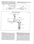
CTS-02V4 User Manual Nitto Construction CTS-02V4 User Manual Safety Precautions Thank you very much for purchasing CTS-02V4. Before using the product, please read this user manual carefully to use CTS-02V4 properly. Regarding Symbols This user manual shows following symbols to prevent harm and damages for the users and the other persons. Please read the text of this user manual after understanding the definitions of the symbols. Disregarding this symbol and improper usage may cause death, serious injury or wounds. Disregarding this symbol and improper usage may cause injury or wounds and also cause physical damages to the person. Examples of Symbols Symbol demonstrates prohibited acts. In some cases, a specific content of prohibition is written in or near Figures. ●Handling of the measurement instrument Do not put CTS-02V4 close to fire. It may cause a fire or damages because heat-sensitive material such as polyvinyl chloride is used for CTS-02V4. Do not put CTS-02V4 at any places that are at risk of spilling water, oil, chemicals etc. It may cause a fire or failure of the instrument. Do not throw CTS-02V4 into a fire. It may cause a fire or injuries from explosion. Nitto Construction A strap is to put the instrument around shoulder in order to prevent the instrument from dropping. An allowable load is 1 kg. Do not use to put anything else around shoulder. It may cause injury. Do not remove the screw attaching a strap. It may cause injury by dropping the instrument and also cause failure of the instrument by dropping the screw inside of the instrument. Do not put the instrument on unstable place. It may cause injury by dropping. ●Usage The hammer unit is made of metal and is a “hammer” object. Improper usage such as brandishing may cause injury and damages. Do not disassemble the instrument. It may cause injury and failure of the instrument. Disassembling will void the warranty of the instrument. Do not use the instrument at any places that are at risk of spilling water, chemicals etc. It may cause a fire or other disasters. Do not use anywhere gas is ignited. It may cause fire or explosion. Misuse of the batteries may cause contamination around a case by leakage of battery fluids and a fire or injuries by explosion. The following restrictions are extremely important. 1. Do not use the combination of different types of batteries such as manganese and alkaline batteries. 2. Please refrain from combining old and new batteries. 3. Please install the batteries in the right direction in terms of positive and negative electrodes. 4. Please remove the batteries from the instrument when left unused for a long period of time. Stop immediately using the instrument if it starts to smoke or smell oddly. Turn the power of the instrument off, remove the batteries and contact our company. The hook of the instrument attached to the strap can only support the mass of the instrument itself. Do not carry heavy goods on the hook. It may cause injury or failure of the instrument by dropping the instrumrnt. Nitto Construction ●Maintenance Do not wipe exterior parts with the liquid containing benzin or thinner. It may be hurmful to the surface of the instrument. ●Miscellaneous 1. The Contents of specifications of the instrument and the user manual may change without prior notice. 2. Reproduction of any parts or entirety of the measurement instrument and user manual is strictly prohibited. 3. The contents of the user manual were prepared carefully to give accurate information. If you have any questions or suspicions, however, please contact the distribution agent. 4. Our company is not responsible for any loss of profits or estimated lost earnings by using the measurement instrument, regardless of what is written above. Please consent to this in advance. 5. This measurement instrument is not designed for use on the equipments or instruments that involve human lives or that require a high reliability. Our company cannot take any responsibilities for damages to property, accidents, or physical injuries caused by using the equipments or instruments. 6. In the case that the instrument and software are eligible for strategic materials (or services) under the provisions of Foreign Exchange and Foreign Trade Control Law, export of the instrument or software outside of Japan must be authorized by the Japanese government. Ⓒ2010 Nitto Construction All rights reserved. Without approval from Nitto Construction, reproduction and making changes of this user manual is prohibited. Microsoft Windows 7, Windows XP, Windows 2000, and Windows NT are registered trademarks of Microsoft Corporations in U.S. and worldwide. Nitto Construction Contents Chapter 1 Name of Various Parts 1.1 Measurement Instrument Body (Table 1-1) 1.2 Hammer Unit (Table 1-2) Chapter 2 Outline 2.1 Outline of Instrument 2.2 Specification of CTS-02V4 (Table 2-1) 2.3 Precautions for Use Chapter 3 Index Values 3.1 Fundamental Principles 3.2 Calculation from Waveform 3.3 Examples of Measured Waveform 3.4 Measured Value 3.5 Allowable range for Each Index Value Chapter 4 Operating Instructions for CTS-02V4-PC Program 4.1 Installing of Driver 4.2 Start-up of CTS-02V4-PC Program 4.3 Set-up and Writing-in of Measurement Parameters 4.4 Browsing of Parameters 4.5 Set-up for Timer 4.6 Processing of Measurement Data 4.6.1 Read-in of Data 4.6.2 Confirmation of Parameters 4.6.3 Display of Waveforms 4.6.4 Copy of Data 4.6.5 Deletion of Data Chapter 5 Operating Instruction for CTS-02V4 Body 5.1 Installing of Batteries 5.2 Connection of Hammer Unit 5.3 Power On and Off Chapter 6 6.1 Method of Measurement Selection of SITE Number 6.2 Selection of Coordinate Number and Confirmation of Data 6.3 Measurement 6.4 Deletion of Data Nitto Construction ※You must read below prior to use CTS-02V4 Thank you very much for purchasing CTS-02V4. Before usage of the product, please read this user manual carefully first in order to deliver superior performance of CTS-02V4 and to continue to use it for many years. After reading, please keep the user manual and the certificate close to the area of first use if needed. 1. Name of Various Parts 1.1 Measurement Instrument Body (Table 1-1) ① ③ ④ ② Table 1-1 No. ① ⑤ Name of Various Parts of Measurement Instrument Body Name Receptor Contents for Connection To be used for connecting CTS-02V4 body to hammer unit. ② USB Port To be used for transferring data from CTS-02V4 body to PC. ③ Display To display the measurement modes and measurement results. Power: To be used to power on/off for CTS-02V4. ④ Control Panel Decide: To be used when you decide for various purposes. Arrows: To be used to select SITE number and coordinate number. ⑤ Battery Pack To install 4 pcs Size AA batteries. Battery pack employs a slide gate system. -6- Nitto Construction 1.2 Hammer Unit (Table 1-2) ⑦ ⑧ ⑥ ⑨ Table2-2 No. Name ⑥ Hammerhead ⑦ Hammer Cap ⑧ Grip ⑨ Name of Various Parts of Hammer Unit Contents To make contact with a target object. To protect the sensor. Do not use the cap side to make contact. To protect the sensor. Do not use the cap side to make contact. Connecting To connect CTS-02V4 body. Code It is connected in advance when delivered the instrument. -7- Nitto Construction 2. Outline 2.1 Outline of Instrument The concrete tester, Concrete Test and Surveyor Type 2 Version 4, is a non-destructive testing instrument that estimates the compressive strength of concrete without causing any damage. This instrument applies to estimation of the compressive strength of concrete structures and integrity assessment such as detection of delamination near concrete surface. In this user manual the instrument will be referred to as the CTS-02V4. 2.2 Specifications of CTS-02V4 (Table 2-1) Table 2-1 Specifications of CTS-02V4 Name Body Size Concrete Test and Surveyor Type 2 Version 4 (CTS-02V4) 108mm×169mm×42mm (Outshoot is not included) Hammer Weight 380g Sampling Clock 0.5μs Measuring Time 2ms Power Supply Connection to PC Record 4 Pcs Size AA Batteries (About 12 hours of Continual Usage) USB is used to connect to PC. It is workable as USB device. Maximum data to be recorded: 128×128×128×100 -8- Nitto Construction 2.3 Precautions for use The hammer unit is precision measuring equipment. It is not a real “hammer.” Please handle it with care. The instrument is made for concrete testing. Do not use it to hammer nails or other “hammering” uses. It may lead to damages to the sensor. The hammer-side of the hammerhead is used for making contact. The hammerhead will eventually flaw the surface after many hits. If the flaws are not major, however, it will have no effect on the measurements. Usually it is enough to use light impact force. Do not hammer too strong. It may lead to damages to the sensor. The opposite side of the hammer-side is the safety cap (yellow-colored plastics) of the sensor. Do not use the cap side to make contact. It may lead to damages to the sensor. The CTS-02V4 is not waterproof or water resistant. Please do not use it during rainfall or areas of extreme high humidity. It may lead to damages to the instrument. When hammering, please use while lightly holding onto the grip. The instrument cannot produce accurate results if hammered while holding the shaft or hammerhead. Please contact at a right angle when hammering the concrete. Diagonally hammering the concrete will not produce accurate results. There is no problem if hammering within 10 from the right angle. The possible measurement time of CTS-02V4 is approximately twelve (12) hours. This possible measurement time is affected by the brands and types of batteries or the climate that it is used. If using the instrument for an extended period of time, please prepare spare batteries. Do not energize over DC6V for the power supply. It will lead damages of the electronic circuit. Do not bend or pull the cable connecting with the hammer and the measurement instrument. It may cause cable disconnection or short-circuit. CTS-02V4 and the hammer unit are precision instruments.Please handle it with care. Please avoid storing under the high humidity or extremely high or low temperature. -9- Nitto Construction 3. Index Values 3.1 Fundamental Principles The concrete structure is considered as the ideal elastic body and the hammer whose mass is M collides against the concrete surface with the initial velocity V and the spring coefficient of the concrete K (See Fig 3-1). In such case the elastic deformation of the concrete surface is generated by the kinetic energy of the hammer. When displacement of the concrete surface generated by collision of the hammer is denoted by x, it can be shown in Equation (3.1) from the law of energy equilibrium. 1 1 2 MV02 Kxmax 2 2 (3.1) According the Hooke’s law, force F can be shown in Equation (3.2). Fmax Kx max (3.2) Fig 3-1 Model of concrete surface The xmax is solved by Equation (3.2) and substituted into Equation (3.1). Thus, Equation (3.3) can be obtained. MK Fmax V0 (3.3) MK means mechanical impedance and can be obtained by dividing the maximum force generated by the initial velocity of the hammer (the initial velocity at the time of impact). The spring coefficient K is the index that corresponds to the elastic coefficient on the concrete surface. It is known about the correlation between the elastic coefficient and the compressive strength. By taking advantage of this fact, the compressive strength can be estimated by the concrete tester, CTS-02V4. In practice, when hammering the maximum impact force is proportional to the 1. 2 power of the impact velocity. Therefore, the impact velocity can be corrected as shown in Equation (3.4) when the mechanical impedance is calculated. MK Fmax V01.2 (3.4) - 10 - Nitto Construction Regarding estimation of strength, the relationship between the mechanical impedance index value and the elastic coefficient of the concrete is shown in the following Equation (3.5). E aZ N (3.5) Here, a is a constant number and N is used as 4 if the elastic coefficient is unchanged at NDT range of strain and at the end (breaking time) or 3 in the case of the normal concrete in taking account the reducing rate of the elastic coefficient. The constant number a depends on the maximum strain amount of the concrete. In the case of the concrete that is led the compressive breakdown at 2250μstrain, the calibration value in the parameter will be about 10-12. - 11 - Nitto Construction 3.2 Calculation from Waveform The waveform of impact force is measured by the accelerometer built-in to CTS-02V4. Fig. 3-2 shows the waveform of impact force when hammering the concrete. The acceleration generated by impact of hammer on the surface of the concrete is actually the decelerated acceleration. In other words, as shown in Equation (3.6), the impact velocity is given by time integration until the acceleration reaches the maximum and the maximum impact force can be computed by multiplying the mass of hammer by the maximum acceleration based on the law of inertia,. Fmax MAmax T2 VA max At dt T1 T3 VR max At dt T2 (3.6) Here, A is the acceleration and T2 is the time that acceleration reaches the maximum. Fig. 3-2 Waveform In the actual concrete, the time until the impact force becomes the maximum is the process that the hammer is pushing onto the concrete surface and the elastic deformation is resulting (active phase). On the other hand, the time after the impact force reaches the maximum is the process that the hammer is pushed back by recovering the elastic deformation of the concrete surface (reactive phase). CTS-02V4 focuses on the reactive phase and used the following Equation (3.7) as an index. Here, number of a power of velocity can be corrected according the impact velocity. - 12 - Nitto Construction ZR Fmax VR1.2 (3.7) The active phase has negative effects on measuring the elastic character such as plasticity of the concrete surface due to the deterioration. The degree of deterioration on the surface can be calculated from the ratio of the velocity in the active phase VA to the velocity in the reactive phase VR. - 13 - Nitto Construction 3.3 Examples of Measured Waveform NOTE: The waveforms shown in Table 3-1 are typical examples. Various waveforms are measured depending on conditions of the concrete. Table 3-1 Examples of Measured Waveform Examples of Measured Waveform Comments Force 1200 1000 800 Waveform of impact force when hammering on healthy concrete 600 It can be obtained as nearly bilaterally 400 symmetric waveform at the peak. 200 Time(μs) 0 0 100 200 300 400 500 600 Force Waveform of impact force when 1200 hammering on deteriorated surface of 1000 concrete 800 The rising time in the active phase is longer 600 in comparison to the healthy concrete. The 400 reason is that the time for the penetration of 200 Time(μs) 0 0 100 200 300 400 500 600 hammer with plastic deformation in the deteriorated surface is included. In contrast influence of the deteriorated surface is small in reactive phase. Waveform of impact force when hammering on the surface of concrete with delamination: Case 1 This is the typical waveform that delamination is clearly observed in the Force 1200 relatively shallow site. The waveform is 1000 bilaterally symmetric in common with 800 healthy surface, but there are some 600 characteristics such as relatively small 400 maximum value of the impact force and long 200 Time(μs) 0 0 100 200 300 400 500 600 contact time with hammer. It can be observed that the impact position shows the same behavior as the leaf spring. The waveform shows the fine bell shape but the duration time of the impact force becomes longer because of the low rigidity in comparison to the healthy concrete. - 14 - Nitto Construction Force Waveform of impact force when 1200 hammering on the surface of concrete 1000 with delamination: Case 2 800 This waveform can be observed when the 600 concrete is about to detach when 400 hammering. The normal waveform cannot be 200 Time(μs) 0 0 500 1000 1500 2000 obtained because the reactive force is not generated when hammering. Note that the horizontal axis (time axis) is totally different from the other waveforms. Waveform of impact force when hammering on the concrete with the aggregate delamination This waveform can be obtained when hammering the concrete surface with the aggregate delamination caused by freezing and thawing action or running water action. Many local peaks are observed and cause a 1200 jagged waveform pattern. It is thought to be Force 1000 due to repeat the phenomena that the 800 hammer impacts on the aggregate and the 600 aggregate breaks down. The concrete surface 400 for obtaining such waveform is shown below. 200 Time(μs) 0 0 200 400 600 800 1000 - 15 - Nitto Construction 3.4 Measured Value Three index values, STR Value (Strength), INDX Value (Index), STAT Value (Status), can be calculated based on a waveforms of impact force in CTS-02V4. The calculated values can be seen in the display. <STR Value> ・STR value is an index value of strength of the concrete. ・Both of the mechanical impedance index value and the spring constant index value can be used to estimate the compressive strength of the concrete. ・By means of set-up of parameters, you can select for which value should be used. *Difference between Mechanical Impedance Index Value and Spring Constant Index Value Mechanical Impedance Index Value ・The strength calibration chart should be used to estimate the compressive strength of the concrete based from the measured STR value. ・Even if the variance of STR values was small, the variance of estimated compressive strength of the concrete may be significantly large by the calibration chart. Example: When the STR value is less than 1.37, change of 0.01 units in STR value results in a change of an average of 0.67 N/mm2. When the STR value is 1.37 and more, change of 0.01 units in STR value results in a change of an average 2.09 N/mm2. Spring Constant Index Value ・Spring constant index value is an index value of spring constant per unit area of the concrete surface and of an estimated strength of concrete. ・The value corresponds to the cube of mechanical impedance index value (in case of high compressive concrete, the value corresponds to the fourth power of mechanical impedance index value). ・The measured STR value can be read directly as the estimated compressive strength (N/mm2). ・Each of measured values will be varied widely if compared to mechanical impedance index value. <INDX Value> ・INDX value is an index value of surface deterioration. ・The value shows the rate between the initial velocity when the hammer contacts the concrete and the velocity of rebound. ・If the measured body is ideally elastic, the value becomes 1; if the surface is deteriorated, the INDX value will increase. ・When the INDX value is over than 1.5 at any time, the strength may be underestimated. ・In such case, it is necessary to polish the concrete surface. - 16 - Nitto Construction <STAT Value> ・ The STAT value is an index value of the ・The value shows the number of local peaks in Local peak Forc delamination. Local peak the first and second halves of the waveform measured (See Figure 3.1). ・The intended delamination is an aggregated delamination that is exposed by freezing and Time thawing of concrete or running water. ・If aggregated delamination exists around the Fig. 3-1 Occurrences of Local Peak concrete surface, several local peaks will appear in measured impact waveforms. ・When estimating the strength of the concrete, the data that STAT value appeared cannot calculate the index value accurately. - 17 - Nitto Construction 3.5 Allowable range for Each Index Value Note: Each index value shown below is the experimental value and only the reference value. It is possible to change significantly depending on the types and conditions of the concrete. It does not guarantee the condition or strength of the concrete. Table 3-2 shows the examples of handling of each index value on the strength estimation. To estimate the strength, the best waveform for the strength estimation is the STR value calculated from the waveform when INDX value is within the range of 0.9 to 1.3 and STAT value is 0 Strength Estimation Table 3-2 Examples of Handling of Each Index Value on Strength Estimation INDX Assessment IDX < 0.90 × Active Phase Reactive Phase 0.90 ≦ IDX ≦ 1.30 ◎ 0 0 ◎ 1.30 < IDX ≦ 1.50 ○ >1 0 △ 1.50 < IDX < 2.00 △ 0 1< × 2.00 ≦ IDX × 1< 1< × STAT Value ◎:Very suitable ○:Suitable △:Not really suitable ×:Not suitable Assessment Surface Deterioration 1. If INDX value ranges between 0.9-1.30, it is judged as unlikely surface deterioration. 2. If INDX value ranges between 1.31-1.49, it is judged as possible surface deterioration. 3. If INDX value is more than 1.50, it is judged as likely surface deterioration. Estimation of Degree of Surface Delamination 1. If STAT value is 0, it is judged as unlikely surface delamination. 2. If STAT value is 1, it is judged as possible surface delamination. 3. If STAT value is more than 2 in the active phase, it is judged as possible aggregate delamination (slight injury) caused by freezing and thawing etc. 4. If STAT value is more than 2 in the reactive phase, it is judged as possible aggregate delamination or void (severe injury) caused by freezing and thawing etc. Note: There are various types of delamination. The delamination that CTS focuses is the aggregate delamination caused by freezing and thawing. In case of the - 18 - Nitto Construction delamination caused by corrosion of reinforcing bar, the waveform will be a clear bell shape and changes of STAT value and INDX value may not be observed. In such case, planar measurement is carried out and location of the delamination may be identified by extraction of location that the STR value is relatively declining. Even in this case, however, it would appear that the detectable depth for delamination is within 50 mm. - 19 - Nitto Construction 4. Operating Instruction for CTS-02V4-PC Program This program is applied to set-up of the initial parameters of CTS-02V4 and reading the data recorded in the memory. 4.1 Installing of Driver ・The device driver for CTS-02V4 should be installed prior to connection of CTS-02V4 to the PC. ・After connected to the PC, CTS-02V4 is recognized as a controllable device. ・The operating system (OS) is Windows XP or above with 32 bit only. ・It is not acceptable for 64 bit version. *Procedure for Installing ① Installing Driver for License ・Insert the accompanying CD-ROM into the PC. ・Execute [INSTALL.BAT] in [TUSBOE47] folder through [DRIVER] folder. ・Although several warning messages will be displayed during installing in Windows 7 and VISTA, please ignore it and continue to install. Fig.4-1 Execution Screen ② Connection CTS-02V4 Body with PC ・Check that CTS-02V4 body is in the initial state after power-on. ・Connect CTS-02V4 body to the PC using an accompanying USB cable. ・The initial state of CTS-02V4 body will be displayed as shown in Fig.4-2. Fig.4-2 Display Screen of Initial State - 20 - Nitto Construction ③ Installing of Device ・After connecting CTS-02V4 body to the PC, the device manager will be started up and be processed for registration of the new device. Fig.4-3 Screen for Installing ●When installing from CD-ROM ・Select [Install the software automatically (Recommended)] in the screen above (See Fig.4-3). ・Click [Next] button. ※When selecting [Install from a list or specific location (Advanced)] ・Assign device driver to [TUSBOE47]→ [DRIVER]→ [sub] in the screen below (See Fig.4-4). ・Click [Next] button. ・Installing is completed and CTS-02V4 can be recognized. - 21 - Nitto Construction Fig.4-4 Screen when Selected [Install from a list or specific location (Advanced)] ④ When installing the device driver unsuccessfully ・Start up the device manager from control panel and search for “unknown device”. ・If you find “unknown device”, click it to renew the driver in advanced setting. - 22 - Nitto Construction 4.2 Start-up of CTS-02V4-PCprogrum ・Once the device becomes usable, a program (CTS-02V4-PC.exe) starts up. ・The initial screen is shown below (See Fig.4-5). ・If the measured data exists in CTS-02V4 body, the site number that was used for the measurement will be displayed in [Site Number] list box shown on the extreme left. ⑥ ⑦ Site Number X-Y-N/STR/INDEX List Box List Box ⑧ ⑨ No. STR/Index List Box SET UP CTS02V4 ① ② ③ List ④ ⑤ ⑩ Fig.4-5 Initial Screen for Start-up Table 4-1 List of Button Name and its Function No. Button Name ① DATA Read To read the data recorded in CTS-02V4 ② DATA Copy To copy the data recorded in CTS-02V4 to the specified folder ③ Delete Site To delete the data recorded in CTS-02V4 ④ Show Parameter ⑤ Show Wave Form To show the waveform Function To check the parameters at the time of measurement ⑥ Parameters Set ⑦ Timer Set To set the timer of CTS-02V4 Connect to To connect CTS-02V4 to the PC CTS-02V4 It will not be displayed when connected ⑧ To set the parameters ⑨ Show Parameter To check the parameters set in CTS-02V4 at the present moment ⑩ Application Exit To exit the program - 23 - Nitto Construction ※ When unable to connect with CTS-02V4 ・Warning dialogue will be displayed as shown below (See Fig.4-6). ・The program will exit when click [OK] button. ・When click [キャンセル (cancel)] button, the initial screen will change a little and [Connect to CTS02V4] button ⑧ will appeared in [SET UPCTS-02V4] list shown on the extreme right. Fig.4-6 Warning Dialog - 24 - Nitto Construction 4.3 Set-up and Writing-in of Measurement Parameters ・Click [Parameters Set] ⑥ button in the initial screen of CTS-02V4-PC. ・The dialog window as shown below will be displayed to input the measurement parameters (See Fig.4-7). ・All parameters in CTS-02V4 can be set using this dialog. ⑪ ⑫ ⑬ ⑭ ⑮ Fig.4-7 Dialog Window <CONCRETE>⑪ ・Select the measuring concrete is Normal or High Compressive by reference to Table 4-2. ・The parameters are different in Normal or High Compressive concrete. Table 4-2 Selection of Measuring Concrete Object Normal High Compressive Meaning Normal concrete (10 N/mm2~30 N/mm2) High compressive concrete (30 N/mm2~150 N/mm2) ※ The mode and parameters for set-up are used for calculation of the actual index values. - 25 - Nitto Construction ・When exiting without set-up, click [Not Set Up] button ⑭. ・When exiting with set-up, click [Set Up] button ⑮. <MEASUREMENT>⑫ (Table 4-3) ・There is a number of measurement items in CTS-02V4. ・Those three items, [Strength(Area Mode)], [Strength(Point Mode)] and [Reactive Side Impedance], make it possible to estimate the compressive strength of the concrete. ・ When you want to read out the compressive strength as N/mm2 directly, select [Strength(Area Mode)] or [Strength(Point Mode)]. ・When you want to read out the compressive strength as the index value, select [Reactive Side Impedance]. ・The rest of items is used except for estimation of the compressive strength of the concrete. [Strength(Point Mode)] ・After hammering at the same position of the concrete twenty times, the mean score will be calculated. ・The mean score will be set automatically within ±20 % range. ・Among the data measured by hammering twenty times, the data beyond the range, if any, will be excluded automatically from calculation of the mean score. ・Since then, the data beyond the range will not be obtained with restrictions. ※ Except for [Strength(Point Mode)], it will not be set the mean score or the range as described above even if hammering at the same position of the concrete twenty times and will be calculated the simple mean score. Table 4-3 Explanation of MEASUREMENT Estimation Items for Contents Compressive Strength It can be readable as N/mm2 directly. It is not applied Strength (Area Mode) ○ statistical processing such as the range setting or no restriction for obtaining the data, even if hammering at the same position of the concrete twenty times. Strength (Point Mode) It can be readable as N/mm2 directly. When hammering ○ at the same position of the concrete, the range will be set with restriction for obtaining the data. It can be calculated from the entire waveforms by Impedance × impact force. It is not possible to estimate the compressive strength of the concrete. - 26 - Nitto Construction Active Side Impedance It can be calculated from the first half of peak of the × waveforms by impact force. It is not possible to estimate the compressive strength of the concrete. It can be calculated from the latter half of peak of the waveforms by impact force. It is necessary to convert for Reactive Side Impedance ○ estimation of the compressive strength of the concrete. Please convert the compressive strength using the conversion formula or the calibration chart provided by manufacturer. ※ The mode and parameters for set up are used for calculation of the actual index values. ・When exiting without set up, click [Not Set Up] button ⑭. ・When exiting with set up, click [Set Up] button ⑮. - 27 - Nitto Construction <Condition>⑬ (Table 4-4) ・The parameters are set up for calculation of the index values. ・The parameters have been already set up based on the results of the calibration test by the manufacturer at the time of delivery. ・Some errors will be observed on the estimated strength of the concrete if parameters are changed by the user side. ・ The numerical numbers of the parameters are inherent to the hammer used. The parameters are shown in the enclosed certificate of the calibration test. ・Please confirm whether the parameters are input correctly before using the instrument. ※ The numerical numbers described in this manual are one of examples. Please note that the numbers are not the parameters of your instrument. ※ Please note that some errors are observed on the estimated strength of the concrete if you use the other hammer without changes of the numbers of the parameters. Table 4-4 Explanation of Condition Items Mass of Hammer Sensitivity Purpose The weight of the hammer used should be entered. The current weight is 380 g. Sensitivity of accelerometer equipped in hammer is input. The numerical numbers are inherent to the accelerometer used. This is a calibrated numerical number from the measured Calibration index value to the strength. This number is determined by the result of the calibration test. This is a power value for conversion of the strength of the Power Value concrete from mechanical impedance index value. If you choose the type of the concrete, it will be set up automatically. This is a trigger value of the measured one. You can set up Trigger Level between 0-80 %. If you reduce the numbers, it becomes to react with a weak impact. In case of the concrete, please set up over 40 %. ※ The mode and parameters for set-up are used for calculation of the actual index values. ・When exiting without set up, click [Not Set Up] button ⑭. ・When exiting with set up, click [Set Up] button ⑮. - 28 - Nitto Construction 4.4 Browsing of Parameters ・The parameters can be confirmed using [Show Parameter] button ⑨. ・When clicking the button ⑨, the parameters can be displayed. You cannot, however, edit or write the parameters. ・After confirmed the parameters, press [Exit] button to exit the dialog. 4.5 Set-up for Timer ・Click [Timer Set] button ⑦ at the initial screen of CTS-02V4-PC. ・The dialog window for setting date and time is shown in Fig.4-8. ・Please refer to the list of the name of button and its function as shown in Table 4-5. ・Present Date appeared is the date and time in internal clock for the PC, not for that of CTS-02V4. ・YY, MM, DD, H, M and S means Year, Month, Day, Hour, Minute and Second at the time of opening the dialog. Fig.4-8 Dialog Window for Setting Date and Time Table 4-5 List of Name of Button and its Function Name Function Cancel To exit the dialog without changes of thermal clock of CTS-02V4. Set Present Date To set the present date and time for CTS-02V4 from that of PC. Set Manual Date To set the arbitrary date and time in YY, MM, DD, H, M and S. - 29 - Nitto Construction 4.6 Processing of Measurement Data 4.6.1 Read-in of Data ・This is way to check the data stored in CTS-02V4. ・The data consists of [Site Number] and coordinate number [X-Y-N/STR/INDEX] . ・CTS-02V4 body is connected to the PC by USB cable. ・After connection is completed, the site number of the stored data will be displayed automatically in the [Site Number] list box. ・Click the site number what you want to read the data in [Site Number] list box. ・When clicking [DATA Read] button ①, the data in the selected site number will be displayed in [X-Y-N/STR/INDEX] list box. ・When clicking the coordinate number in [X-Y-N/STR/INDEX] list box, the measured data will be displayed in [No. STR/Index] list box. ・You can find the strength value of the concrete and Index value in [No. STR/Index] list box. Site Number List Box X-Y-N/STR/INDEX List Box ⑯ ① ④ ② ⑤ No.STR/Index List Box ③ Fig.4-9 Screen at Start-up 4.6.2 Confirmation of Parameters ・When confirming what parameters were used for the measured data specified by clicking the coordinate number in [X-Y-N/STR/INDEX] list box, click [Show Parameter] button ④. ・You can find the parameters used for measurement. - 30 - Nitto Construction 4.6.3 Displaying of Waveforms ・When clicking [Show Wave Form] button ⑤, dialog of displaying waveform is appeared as shown in Fig.4-10. ・Please refer to the list of the name of button and its function as shown in Table 4-6. ・The first waveform at the measurement point will be displayed in this dialog. ・The measured waveform number, estimated strength value and Index value are displayed at the top of the dialog (shown in red box of Fig.4-10). ※ These values are recalculated by the program of PC and may be different slightly from the measured values with CTS-02V4. It can be checked in this dialog whether the waveform is measured accurately or not. Fig.4-10 Dialog of Displaying Waveform Table 4-6 List of Name of Button and its Function Name Function Back To display the previous waveform. Next To display the next waveform. + To enlarge waveform. Init To display the initial waveform (all measured data). Exit To exit the dialog. - 31 - Nitto Construction 4.6.4 Copy of Data ・When clicking [Data Copy] button ②, the data of the specified SITE will be transferred to the PC. ※ However, the following warning message (See Fig.4-11) will be displayed if the storage folder in the PC side is not specified. Fig.4-11 Screen of Warning ・In this case, please input the folder name in [Where Data will be saved] shown on top of the screen. Otherwise, select the folder from the browser (See Fig.4-12) available by clicking [Ref.] button ⑯ or create a new folder. Fig.4-12 Screen of Browser ※ The data copied in the PC is shown in Fig.4-13. ・ [Area-***.csv] ⑰ is the csv file to make a drawing of a map of the strength distribution based on the data measured in area mode. The mean score of the measured data is written in the 128-by-128 cells. ・In [Measure-***.csv] ⑱, the mean scores of the index value, Index value and Status value are recorded in order of measurement. - 32 - Nitto Construction ・In [Over-All-***.csv] ⑲, all data about the measurement time, measuring point and the number of times of measurement are recorded. ・ The data of waveform is recorded as the value of AD conversion directly in [WaveForm-aaa-bbb-ccc.csv] ⑳ where aaa is X axial location, bbb is Y axial location and ccc is measurement number. ⑰ ⑱ ⑲ ⑳ Fig. 4-13 Data copied in PC 4.6.5 Deletion of Data ・When selecting the site number that you want to delete in Site Number list box and clicking [Delete Site] button ③, a warning dialog will be displayed as shown in Fig.4-14. ・If you select [OK], all data in the selected site will be deleted. ・If you select [Cancel], it will return without deletion. ・It is also possible to delete the data by operation of CTS-02V4 body. ※ Once the data was deleted, it is impossible to turn it back. Fig.4-14 Warning Dialog - 33 - Nitto Construction 5. Operating Instruction for CTS-02V4 Body 5.1 Installing of Batteries ・Four packs of Size AA batteries are used for the power supply. ・Open the slide gate of the battery pack (Fig.5-1) on the reverse side of the measurement instrument. ・Install the batteries in the right direction in terms of positive and negative electrodes. ・It is possible to use different brands or types of batteries. Fig.5-1 Battery Pack ※ Installing the batteries in wrong direction in terms of the electrodes may lead to damages of the battery pack and the instrument. Please refrain from combination of old and new or different types of batteries (ex. manganese and alkaline batteries). 5.2 Connection of Hammer Unit ・ Although the instrument body and the hammer unit are already connected, the hammer unit is removable. ・Hold the grip firmly and withdraw the cable slowly when removing the hammer unit. ・Plug the hammer unit connecter into the receptor of the instrument body. ・There exist a direction in the receptor and connector. Check the shape of the receptor and connector and plug the connector into the receptor carefully. ・CTS-02V4 can be stored as connected the instrument body and the hammer unit. ・It is necessary to remove the hammer unit Fig.5-2 Instrument Body and Hammer Unit only in special circumstances. Otherwise, you don’t need to remove it. ※ The connector will not detach by simply pulling the cable. Do not pull the cable. It may cause breaking of cable and other problems. - 34 - Nitto Construction 5.3 Power On and Off ・After installing the batteries, press the power button for three seconds to power on. ・Once CTS-02V4 is started up, information on version of measurement instrument, date and time in the internal clock and parameters set-up are displayed, and then move to SITE selection screen (See Fig.5-3). This is an initial state. ・During power on of CTS-02V4, press button for 3 seconds to power off. Fig.5-3 SITE Selection Screen - 35 - Nitto Construction 6. Method of Measurement 6.1 Selection of SITE Number ・In the initial state of CTS-02V4、press or button to select the SITE number for a storage of the data. ・When pressing button, SITE number will decrease, while pressing button, SITE number will increase. ・When the data was recorded in SITE, it will display as USED shown in Fig.6-1, while the data was not recorded in SITE, it will display as EMPTY shown in Fig.6-2. ・When SITE number is selected to use, press button. ・Each SITE number contain X-Y coordinate of 128-by-128 and each measured data is recorded in the selected SITE number. (One hundred of data can be recorded in each coordinate number. Fig.6-1 Example of Display for USED Fig.6-2 Example of Display for EMPTY 6.2 Selection of Coordinate Number and Confirmation of Data ・When SITE number is selected, it becomes LOOKUP mode. ・LOOKUP mode is a mode to read out the data recorded in CTS-02V4. ・When the recorded data exists in the specified SITE number, the numbers of the measured data and the mean score of the measured data are displayed as shown in Fig.6-3. ・When the recorded data does not exist in the specified SITE number, the message of [Site File creating] shows up and then the screen is displayed as shown in Fig.6-4. Current status of instrument Mean score of measured data Number of Fig.6-3 Screen When Recorded Data exists Measured data Fig.6-4 Screen When Recorded Data Does Not exist - 36 - Nitto Construction ・Press or button for increase or decrease of the X axis in the cordinate (X, Y). ・Press or button for increase or decrease of the Y axis in the cordinate (X, Y). ・When pressing button at LOOKUP mode, it returs to the initial state. ※In the specified coordinate number where the measured data has already existed, it is not possible to measure newly or additionally. - 37 - Nitto Construction 6.3 Measurement ・When selecting the arbitrary coordinate number that the measured data does not exist and then pressing button, it becomes a waiting-for-measurement screen as shown in Fig.6-5. ・When screen becomes a state of waiting-for-measurement, the display will change from LOOKUP mode (Fig.6-4) to MEAS mode (Fig.6-5). In this state you can start hammering. Current status of instrument Fig.6-5 Waiting-For-Measurement Screen ・The data will be renewed with each effective hammering. The strength index value (STR value), the surface deterioration index value (INDX value) and the delamination index value (STAT value) will be calculated and displayed in the screen. Fig.6-6 shows the screen of display when first hammering is completed and Table 6-1 shows the list of the items and its content. Fig.6-6 Screen at First Hammering Table 6-1 Items and Contents Item Content SITE Site number PNT(***,***) Coordinate number MN N STR INDX STAT Mean score of strength index value recorded Number of measured data recorded Strength index value with each impact Surface deterioration index value with each impact Delamination index value each impact - 38 - with Nitto Construction ・When the first hammering is completed, it is not determined whether the data is adoptable or not. MN and N remain 0. If there is nothing wrong with the data, hammering should be continued. ・At the second hammering, the data of the first hammering is recorded and the mean score and the numbers of measurement are renewed. ・If there is something wrong with the measured data, press button twice so that the measured data becomes ineffective and is deleted from measured waveform. ( When pressing button and followed by pressing button, judgement of ineffectiveness is released.) ・When finishing the measurement, press button. (At this stage, the number of the measured point and the mean value are settled.) ※Please note that the data of the last waveform is not reflected in calculation of the mean score unless button is pressed. When pressing button, the screen will return to LOOKUP mode that the recorded data exists (See Figure 6-3). ・The data cannot be recorded if the impact was too strong or too light. in CTS-02V4. Please check the impact strength by trying to hammer a few times prior to a real hammering. After hammering, electronic sound indicates if it is a proper hammering or not ※Bleep once: Normal, Bleep three times: Too strong, No bleep: Too light 6.4 Deletion of Data ・CTS02V4 body can delete the data with each coordinate number. ・When selecting the coordinate number that you want to delete at LOOKUP mode (See Fig.6-3) and pressing button, it sounds the beep and the screen of display changes as shown in Fig.6-7. ・In this state, all data recorded in the specified coordinate number will be deleted by pressing button. ・When you don’t want to delete, press button and return to LOOKUP mode (See Fig.6-3). *You cannot delete all data in SITE at once. Fig.6-7 Screen of Deletion of Data - 39 - Nitto Construction Manufacturer : Nitto Construction Co. Ltd. 1344-5, Oumu, Town Oumu, Monbetsu, Hokkaido, 098-1702,Japan Tel:+81-158-84-2715 Fax:+81-158-88-3031 E-mail:[email protected] - 40 -